MI SENSOR API
REVISION HISTORY
| Revision No. | Description |
Date |
|---|---|---|
| 3.0 | 12/04/2020 | |
| 3.1 | 03/30/2021 | |
| 08/25/2021 | ||
| 3.2 | 12/22/2021 | |
| 3.3 | 10/27/2022 | |
| 3.4 | 01/11/2023 | |
| 3.5 | 03/15/2023 | |
| 3.5 | 04/17/2023 | |
| 3.6 | 04/24/2025 |
1. OVERVIEW
1.1. Module Description
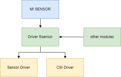
The MI_SENSOR module serves as a software middleware layer between specific sensor drivers and other modules. It provides unified function implementations and calling interfaces for different sensor drivers. By abstracting and standardizing the common behaviors of various sensors, it allows upper-layer applications to operate without needing to focus on the specific implementations of the underlying sensor drivers. Through the different APIs of the MI_SENSOR module, applications can invoke the corresponding implementations of the underlying sensor drivers, enabling functionalities such as sensor activation, retrieval of sensor interface information, and adjustments to resolution and frame rates.
Keyword:
-
Pad
Sensor hardware Jack location.
-
Plane
The name of the channel under the pad.
-
Res
Abbreviation for resolution.
-
Orien
Determine the direction, and set the sensor to mirror horizontally and vertically.
-
VC
Virtual Channel.
1.2. BASIC ARCHITECTURE
When the sensor driver is loaded via insmod, it registers itself at a specified location through the driver parameter chmap. The MI_SENSOR APIs can then retrieve the pointer to the corresponding sensor driver at that location using the associated padId.
Applications can access specific implementation functions within the target sensor driver through the APIs provided by MI_SENSOR. Additionally, other modules also interact with sensors on different pads via the internal APIs of MI_SENSOR.
1.3. FUNCTIONAL DESCRIPTION
MI_SENSOR supports the following features:
-
Enable/disable the sensor
-
Get and set the sensor's resolution
-
Retrieve sensor information for the corresponding pad
-
Get and set the frame rate
-
Get and set the current mirror/flip status
-
Get and set the HDR mode
1.4. APPLICATION SCENARIOS
MI_SNESOR currently supports the following deployment environments, all of which allow development using the MI_SENSOR API:
-
Pure Linux environment
-
Pure RTOS environment
-
Dual-OS environment
1.5. CHIPSET VARIATIONS
The MI_SENSOR module primary hardware variations between chipsets include: mclk frequency and supported sensor interface types
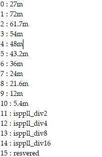
1.5.1. Souffle
-
mclk supported frequency:
-
sensor supported interface:
INTERFACE TYPE SENSOR PAD BT656 0、1 BT1120 0 MIPI 0、1、2、3
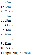
1.5.2. Iford
-
mclk supported frequency:
-
sensor supported interface:
INTERFACE TYPE SENSOR PAD MIPI 0、2
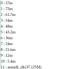
1.5.3. Pcupid
-
mclk supported frequency:
-
sensor supported interface:
INTERFACE TYPE SENSOR PAD BT656 0 parallel 0 MIPI 0、2
1.6. WORKING PRINCIPLE
MI_SENSOR, as a software middleware layer, is not involved in hardware-related working principles. The following describes the actual role of MI_SENSOR using the MI_SNR_Enable call process as an example:
When an upper-layer application calls the MI_SNR_Enable interface, the MI_SENSOR layer locates the corresponding poweron function of the sensor driver based on the provided pad ID. Inside the poweron function, the sensor driver may also invoke sensorif APIs provided by MI_SENSOR, adjusting the implementation according to different sensors' power-on sequences. After execution, the function returns the result to the MI_SENSOR layer, which then passes it back to the MI_SNR_Enable caller.
This process demonstrates how MI_SENSOR abstracts hardware differences, allowing upper-layer applications to control sensors uniformly without dealing with low-level driver specifics.

1.7. DEVELOPMENT WORKFLOW
The implementation of MI_SENSOR APIs depends on the underlying Sensor Driver. Therefore, before developing with MI_SENSOR APIs, the corresponding sensor driver must be completed first.
For details, please refer to:
1.7.1 COMPILATION CONFIGURATION
-
enter alkaid project root directory, make menuconfig
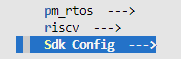
-
press Enter to choose Sdk Config sub-options
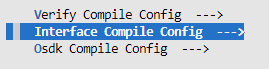
-
press Enter to choose Interface Compile Config sub-options

-
Press the spacebar to select the SENSOR submodule and recompile the project.
Upon successful compilation, mi_sensor.ko will be generated at sdk/interface/src/sensor. Header file mi_sensor.h and mi_sensor_datatype.h will be release to project/release. In pure linux environment they are automatically packaged into system images by default. While in dualos environment, they are excluded from default image packaging (requires manual compilation and installation)
1.7.2 API CALL FLOW

MI_SENSOR API Calling Sequence
-
Enable/disable HDR mode
-
Query available resolutions supported by the current sensor driver
-
Set the desired resolution
-
Configure the frame rate (fps)
-
Enable the sensor
-
Disable the sensor
-
Exit the application
1.8. SAMPLE CODE
This example demonstrates the development workflow based on the MI_SENSOR API.
#include <stdio.h>
#include "mi_sys.h"
#include "mi_sensor.h"
#include <string.h>
#include <stdarg.h>

void ST_Flush(void)
{
    int c;

    while((c = getchar()) != '\n' && c != EOF);
}

int ST_Scanf(const char *format, ...)
{
    int     ret = 0;
    va_list args;

    va_start(args, format);
    ret = vscanf(format, args);
    va_end(args);

    if (ret == 0)
    {
        printf("Error:scanf fail\n");
        return -1;
    }

    return 0;
}

int main(int argc, char **argv)
{
    MI_SNR_PADID eSnrPadId = 0;
    MI_VIF_GROUP GroupId = 0;
    MI_S32 s32Ret = 0;
    MI_BOOL bHDR = 0;
    MI_U32 u32ResCount = 0;
    MI_U8 u8ResIndex =0;
    MI_U8 u8ChocieRes = 0xff;
    MI_S32 s32Input =0;
    MI_U32 u32SnrFps = 30;
    MI_SNR_Res_t stRes;
    MI_SNR_PADInfo_t  stPad0Info;
    MI_SNR_PlaneInfo_t stSnrPlane0Info;
    memset(&stRes, 0x0, sizeof(MI_SNR_Res_t));
    memset(&stPad0Info, 0x0, sizeof(MI_SNR_PADInfo_t));
    memset(&stSnrPlane0Info, 0x0, sizeof(MI_SNR_PlaneInfo_t));


    MI_SYS_Init(0);

    s32Ret = MI_SNR_SetPlaneMode(eSnrPadId,bHDR);
    if(s32Ret != MI_SUCCESS)
    {
        printf("set sensor:%d plane mode failed\n", eSnrPadId);
        goto EXIT;
    }

    s32Ret = MI_SNR_QueryResCount(eSnrPadId, &u32ResCount);
    if(s32Ret != MI_SUCCESS)
    {
        printf("query sensor:%d res failed\n", eSnrPadId);
        goto EXIT;
    }

    for(u8ResIndex=0; u8ResIndex < u32ResCount; u8ResIndex++)
    {
        s32Ret =MI_SNR_GetRes(eSnrPadId, u8ResIndex, &stRes);
        if(s32Ret != MI_SUCCESS)
        {
            printf("get sensor:%d res:%d failed\n", eSnrPadId,u8ResIndex);
            goto EXIT;
        }
        printf("index %d, Crop(%d,%d,%d,%d), outputsize(%d,%d), maxfps %d, minfps %d, ResDesc %s\n",
        u8ResIndex,
        stRes.stCropRect.u16X, stRes.stCropRect.u16Y, stRes.stCropRect.u16Width,stRes.stCropRect.u16Height,
        stRes.stOutputSize.u16Width, stRes.stOutputSize.u16Height,
        stRes.u32MaxFps,stRes.u32MinFps,
        stRes.strResDesc);
    }

    if(u8ChocieRes >= u32ResCount && u8ChocieRes != 0xff)
    {
        printf("res set err  %d > =cnt %d\n", u8ChocieRes, u32ResCount);
        s32Ret = -1;
        goto EXIT;
    }
    else if(u8ChocieRes == 0xff)
    {
        printf("choice which resolution use, cnt %d\n", u32ResCount);
        do
        {
            ST_Scanf("%d", &s32Input);
            u8ChocieRes = (MI_U8)s32Input;
            ST_Flush();
            s32Ret = MI_SNR_QueryResCount(eSnrPadId, &u32ResCount);
            if(s32Ret != MI_SUCCESS)
            {
                printf("query sensor:%d res failed\n", eSnrPadId);
                goto EXIT;
            }
            if(u8ChocieRes >= u32ResCount)
            {
                printf("choice err res %d > =cnt %d, choice again\n", u8ChocieRes, u32ResCount);
            }
            else
            {
                break;
            }
        }while(1);
        printf("You select %d res\n", u8ChocieRes);
    }

    s32Ret = MI_SNR_GetRes(eSnrPadId, u8ChocieRes, &stRes);
    if(s32Ret != MI_SUCCESS)
    {
        printf("get sensor:%d res:%d failed\n", eSnrPadId,u8ChocieRes);
        goto EXIT;
    }

    s32Ret = MI_SNR_SetRes(eSnrPadId,u8ChocieRes);
    if(s32Ret != MI_SUCCESS)
    {
        printf("set sensor:%d res:%d failed\n", eSnrPadId,u8ChocieRes);
        goto EXIT;
    }

    if(u32SnrFps <= stRes.u32MaxFps && u32SnrFps >= stRes.u32MinFps)
    {
        s32Ret =  MI_SNR_SetFps(eSnrPadId,u32SnrFps);
        if(s32Ret != MI_SUCCESS)
        {
            printf("set  sensor:%d fps failed\n", eSnrPadId);
            goto EXIT;
        }
    }

    s32Ret = MI_SNR_Enable(eSnrPadId);
    if(s32Ret != MI_SUCCESS)
    {
        printf("enable sensor:%d failed\n", eSnrPadId);
        goto EXIT;
    }

    s32Ret = MI_SNR_Disable(eSnrPadId);
    if(s32Ret != MI_SUCCESS)
    {
        printf("enable sensor:%d failed\n", eSnrPadId);
        goto EXIT;
    }
    MI_SYS_Exit(0);
EXIT:
    return s32Ret;
}
2. API REFERENCE
| API Name | Function |
|---|---|
| MI_SNR_Enable | Sensor Enable |
| MI_SNR_Disable | Sensor Disable |
| MI_SNR_GetPadInfo | Get Sensor pad information |
| MI_SNR_GetPlaneInfo | Get Sensor channel information |
| MI_SNR_GetFps | Get Sensor current frame rate |
| MI_SNR_SetFps | Set Sensor frame rate |
| MI_SNR_GetAnadecSrcAttr | Get analog decode input param |
| MI_SNR_SetAnadecSrcAttr | Set the signal channel parameter |
| MI_SNR_QueryResCount | Get Sensor supported resolution count |
| MI_SNR_GetRes | Get sensor resolution by corresponding index |
| MI_SNR_GetCurRes | Get Sensor current resolution |
| MI_SNR_SetRes | Set Sensor resolution |
| MI_SNR_SetOrien | Set Sensor orientation |
| MI_SNR_GetOrien | Get Sensor orientation attribute |
| MI_SNR_SetPlaneMode | Set Sensor plane mode |
| MI_SNR_GetPlaneMode | Get Sensor plane mode |
| MI_SNR_CustFunction | Set sensor customization function |
| MI_SNR_InitDev | Initialize Sensor device |
| MI_SNR_DeInitDev | De-initialize Sensor device |
2.1. MI_SNR_Enable
-
Function
Set sensor corresponding pad enable
-
Syntax
MI_S32 MI_SNR_Enable(MI_SNR_PADID ePADId);
-
Parameter
Parameter Name Description Input/Output ePADId SENSOR Pad ID
Range: [0, MI_SNR_MAX_PAD_NUM].Input -
Return Value
-
MI_OK: Successful
-
Non-zero: Failed, see error code for details
-
-
Requirement
-
Header: mi_sensor_datatype.h, mi_sensor.h
-
Library: libmi_sensor.a
-
-
Note
-
Before calling this function, ensure sensor pad is not initialized. If the sensor pad has been enabled already, use MI_SNR_Disable to deinitialize the pad.
-
Before enabling this API, MI_SNR_SetPlaneMode and MI_SNR_SetRes must be set.
-
Because the MI SNR module does not interact with the DRAM, there is no need to bind it with the backend module; the data flow will automatically go to the MI Vif.
-
-
Example
Examples of initialization and exit are as follows:

MI_U32 u32ResCount =0; MI_U8 u8ResIndex =0; MI_U8 u8ChocieRes =0; MI_SNR_PADID eSnrPad= E_MI_SNR_PAD_ID_0; MI_SNR_QueryResCount(eSnrPad, &u32ResCount); for(u8ResIndex=0; u8ResIndex < u32ResCount; u8ResIndex++) { MI_SNR_GetRes(E_MI_SNR_PAD_ID_0, u8ResIndex, &stRes); printf("index %d, Crop(%d,%d,%d,%d), outputsize(%d,%d), maxfps %d, minfps %d, ResDesc %s\n",u8ResIndex, stRes.stCropRect.u16X, stRes.stCropRect.u16Y, stRes.stCropRect.u16Width,stRes.stCropRect.u16Height,stRes.stOutputSize.u16Width, stRes.stOutputSize.u16Height, stRes.u32MaxFps,stRes.u32MinFps, stRes.strResDesc); } printf("select res\n"); scanf("%c", &select); if(E_MI_SNR_HDR_TYPE_OFF== eHdrType) { MI_SNR_SetPlaneMode(eSnrPad, FALSE); } else { MI_SNR_SetPlaneMode(eSnrPad, TRUE); } MI_SNR_SetRes(eSnrPad,u8ResIdx); MI_SNR_Enable(eSnrPad); /*****************************/ /* Exit call interface */ /*****************************/ MI_SNR_Disable(eSnrPad); -
Related API
2.2. MI_SNR_Disable
-
Function
Set sensor corresponding pad disable
-
Syntax
MI_S32 MI_SNR_Disable(MI_SNR_PADID ePADId);
-
Parameter
Parameter Name Description Input/Output ePADId SENSOR Pad ID
Range: [0, MI_SNR_MAX_PAD_NUM).Input -
Return Value
-
MI_OK: Successful
-
Non-zero: Failed, see error code for details
-
-
Requirement
-
Header: mi_sensor_datatype.h, mi_sensor.h
-
Library: libmi_sensor.a
-
-
Example
Refer to MI_SNR_Enable .
-
Related API
2.3. MI_SNR_GetPadInfo
-
Function
Get sensor pad information
-
Syntax
MI_S32 MI_SNR_GetPadInfo(MI_SNR_PADID ePADId, MI_SNR_PADInfo_t *pstPadInfo);
-
Parameter
Parameter Name Description Input/Output ePADId SENSOR Pad ID
Range: [0, MI_SNR_MAX_PAD_NUM).Input pstPadInfo SENSOR pad attribute pointer Output -
Return Value
-
MI_OK: Successful
-
Non-zero: Failed, see error code for details
-
-
Requirement
-
Header: mi_sensor_datatype.h, mi_sensor.h
-
Library: libmi_sensor.a
-
2.4. MI_SNR_GetPlaneInfo
-
Function
Get sensor plane information
-
Syntax
MI_S32 MI_SNR_GetPlaneInfo(MI_SNR_PADID ePADId, MI_U32 u32PlaneID, MI_SNR_PlaneInfo_t *pstPlaneInfo);
-
Parameter
Parameter Name Description Input/Output ePADId SENSOR Pad ID
Range: [0, MI_SNR_MAX_PAD_NUM).Input u32PlaneID SENSOR plane ID
Range: [0, MI_SNR_MAX_PLANE_NUM).Input pstPlaneInfo SENSOR plane information Output -
Return Value
-
MI_OK: Successful
-
Non-zero: Failed, see error code for details
-
-
Requirement
-
Header: mi_sensor_datatype.h, mi_sensor.h
-
Library: libmi_sensor.a
-
2.5. MI_SNR_GetFps
-
Function
Get sensor frame rate
-
Syntax
MI_S32 MI_SNR_GetFps(MI_SNR_PADID ePADId, MI_U32 *pFps);
-
Parameter
Parameter Name Description Input/Output ePADId SENSOR Pad ID
Range: [0, MI_SNR_MAX_PAD_NUM).Input pFps Frame rate pointer Output -
Return Value
-
MI_OK: Successful
-
Non-zero: Failed, see error code for details
-
-
Requirement
-
Header: mi_sensor_datatype.h, mi_sensor.h
-
Library: libmi_sensor.a
-
-
Note
The obtained FPS range is:
Min * 1000 < FPS < Max * 1000: accurate to 3 decimal places.
-
Related API
2.6. MI_SNR_SetFps
-
Function
Set sensor frame rate
-
Syntax
MI_S32 MI_SNR_SetFps(MI_SNR_PADID ePADId, MI_U32 u32Fps);
-
Parameter
Parameter Name Description Input/Output ePADId SENSOR Pad ID
Range: [0, MI_SNR_MAX_PAD_NUM).Input u32Fps Frame rate Input -
Return Value
-
MI_OK: Successful
-
Non-zero: Failed, see error code for details
-
-
Requirement
-
Header: mi_sensor_datatype.h, mi_sensor.h
-
Library: libmi_sensor.a
-
-
Note
FPS has two value ranges:
-
Min < fps < max: Accurate to one digit
-
min*1000 < fps < max*1000: Accurate to 3 decimal places
The maximum/minimum value of FPS is the max/min FPS corresponding to the resolution index when MI_SNR_SetRes is set.
-
-
Related API
2.7. MI_SNR_GetAnadecSrcAttr
-
Function
Get analog decode input parameter.
-
Syntax
MI_S32 MI_SNR_GetAnadecSrcAttr(MI_SNR_PADID  ePADId,
MI_U32 u32PlaneID, MI_SNR_Anadec_SrcAttr_t *pstSrcAttr);
-
Parameter
Parameter Name Description Input/Output ePADId SENSOR Pad ID
Range: [0, MI_SNR_MAX_PAD_NUM).Input u32PlaneID SENSOR Plane ID
Range: [0, MI_SNR_MAX_PLANE_NUM).Input pstSrcAttr Signal source parameterparam Input -
Return Value
-
MI_OK: Successful
-
Non-zero: Failed, see error code for details
-
-
Requirement
-
Header: mi_sensor_datatype.h, mi_sensor.h
-
Library: libmi_sensor.a
-
-
Note
This function is applicable to analog decode sensor only.
-
Related API
2.8. MI_SNR_SetAnadecSrcAttr
-
Function
Set the signal channel parameter.
-
Syntax
MI_S32 MI_SNR_SetAnadecSrcAttr(MI_SNR_PADID   ePADId,
MI_U32 u32PlaneID, MI_SNR_Anadec_SrcAttr_t *pstSrcAttr);
-
Parameter
Parameter Name Description Input/Output ePADId SENSOR Pad ID Range: [0, MI_SNR_MAX_PAD_NUM). Input u32PlaneID SENSOR Plane ID Range: [0, MI_SNR_MAX_PLANE_NUM). Input pstSrcAttr Signal source parameter Input -
Return Value
-
MI_OK: Successful
-
Non-zero: Failed, see error code for details
-
-
Requirement
-
Header: mi_sensor_datatype.h, mi_sensor.h
-
Library: libmi_sensor.a
-
-
Note
This interface is suitable for where there are multiple signal settings on one sensor pad; For example, set the resolution of the 4 AHD sensors of a BT656 respectively.
-
Related API
2.9. MI_SNR_QueryResCount
-
Function
Get sensor supported resolution count
-
Syntax
MI_S32 MI_SNR_QueryResCount(MI_SNR_PADID ePADId,
MI_U32 *pu32ResCount);
-
Parameter
Parameter Name Description Input/Output ePADId SENSOR Pad ID
Range: [0, MI_SNR_MAX_PAD_NUM).Input *pu32ResCount SENSOR pad supported resolution count Output -
Return Value
-
MI_OK: Successful
-
Non-zero: Failed, see error code for details
-
-
Requirement
-
Header: mi_sensor_datatype.h, mi_sensor.h
-
Library: libmi_sensor.a
-
-
Example
Please refer to the example given in MI_SNR_GetRes
-
Related API
2.10. MI_SNR_GetRes
-
Function
Get the corresponding resolution from the index in resolution mapping table
-
Syntax
MI_S32 MI_SNR_GetRes(MI_SNR_PADID ePADId, MI_U8 u8ResIdx,
MI_SNR_Res_t *pstRes);
-
Parameter
Parameter Name Description Input/Output ePADId SENSOR Pad ID
Range: [0, MI_SNR_MAX_PAD_NUM).Input u8ResIdx Index in resolution mapping table Input *pstRes Resolution corresponding to the serial number Output -
Return Value
-
MI_OK: Successful
-
Non-zero: Failed, see error code for details
-
-
Requirement
-
Header: mi_sensor_datatype.h, mi_sensor.h
-
Library: libmi_sensor.a
-
-
Example
Below is an example of obtaining resolution list and selecting corresponding resolution setting:
MI_U32 u32ResCount =0; MI_U8 u8ResIndex =0; MI_U8 u8ChocieRes =0; MI_SNR_QueryResCount(E_MI_SNR_PAD_ID_0, &u32ResCount); for(u8ResIndex=0; u8ResIndex < u32ResCount; u8ResIndex++) { MI_SNR_GetRes(E_MI_SNR_PAD_ID_0, u8ResIndex, &stRes); printf("index %d, Crop(%d,%d,%d,%d), outputsize(%d,%d), maxfps %d, minfps %d, ResDesc %s\n",u8ResIndex, stRes.stCropRect.u16X, stRes.stCropRect.u16Y, stRes.stCropRect.u16Width,stRes.stCropRect.u16Height,stRes.stOutputSize.u16Width, stRes.stOutputSize.u16Height,stRes.u32MaxFps,stRes.u32MinFps,stRes.strResDesc); } printf("select res\n"); scanf("%c", &select); MI_SNR_SetRes(E_MI_SNR_PAD_ID_0,u8ResIdx); MI_SNR_GetCurRes(E_MI_SNR_PAD_ID_0, &u8ResIndex, &stRes); -
Related API
2.11. MI_SNR_GetCurRes
-
Function
Get sensor current resolution and its position in the resolution mapping table
-
Syntax
MI_S32 MI_SNR_GetCurRes(MI_SNR_PADID ePADId, MI_U8 *pu8CurResIdx, MI_SNR_Res_t *pstCurRes);
-
Parameter
Parameter Name Description Input/Output ePADId SENSOR Pad ID
Range: [0, MI_SNR_MAX_PAD_NUM).Input *pu8CurResIdx Current resolution index Output *pstCurRes Current resolution information Output -
Return Value
-
MI_OK: Successful
-
Non-zero: Failed, see error code for details
-
-
Requirement
-
Header: mi_sensor_datatype.h, mi_sensor.h
-
Library: libmi_sensor.a
-
-
Example
Please refer to the example given in MI_SNR_GetRes
-
Related API
2.12. MI_SNR_SetRes
-
Function
Set sensor pad output resolution
-
Syntax
MI_S32 MI_SNR_SetRes(MI_SNR_PADID ePADId, MI_U8 u8ResIdx);
-
Parameter
Parameter Name Description Input/Output ePADId SENSOR Pad ID
Range: [0, MI_SNR_MAX_PAD_NUM).Input u8ResIdx Index in resolution mapping table Input -
Return Value
-
MI_OK: Successful
-
Non-zero: Failed, see error code for details
-
-
Requirement
-
Header: mi_sensor_datatype.h, mi_sensor.h
-
Library: libmi_sensor.a
-
-
Note
In default case, the relation between vif Dev and SensorPad is: vif Dev0 -> SensorPad0, vif Dev1 -> SensorPad1.
-
Example
Please refer to the example given in MI_SNR_GetRes
-
Related API
2.13. MI_SNR_SetOrien
-
Function
Set sensor image orientation attribute
-
Syntax
MI_S32 MI_SNR_SetOrien(MI_SNR_PADID ePADId, MI_BOOL
bMirror, MI_BOOL bFlip);
-
Parameter
Parameter Name Description Input/Output ePADId SENSOR Pad ID
Range: [0, MI_SNR_MAX_PAD_NUM).Input bMirror Mirror orientation enable Input bFlip Flip orientation enable Input -
Return Value
-
MI_OK: Successful
-
Non-zero: Failed, see error code for details
-
-
Requirement
-
Header: mi_sensor.h
-
Library: libmi_sensor.a
-
-
Example
The API can be used alone.
-
Related API
2.14. MI_SNR_GetOrien
-
Function
Get sensor image orientation attribute
-
Syntax
MI_S32 MI_SNR_GetOrien(MI_SNR_PADID ePADId, MI_BOOL *pbMirror, MI_BOOL *pbFlip);
-
Parameter
Parameter Name Description Input/Output ePADId SENSOR Pad ID
Range: [0, MI_SNR_MAX_PAD_NUM).Input *pbMirror Mirror orientation enable Output *pbFlip Flip orientation enable Output -
Return Value
-
MI_OK: Successful
-
Non-zero: Failed, see error code for details
-
-
Requirement
-
Header: mi_sensor.h
-
Library: libmi_sensor.a
-
-
Related API
2.15. MI_SNR_SetPlaneMode
-
Function
Set sensor plane mode
-
Syntax
MI_S32 MI_SNR_SetPlaneMode(MI_SNR_PADID ePADId, MI_BOOL
bEnable);
-
Parameter
Parameter Name Description Input/Output ePADId SENSOR Pad ID
Range: [0, MI_SNR_MAX_PAD_NUM).Input bEnable Must be set to TRUE if HDR is in use, and FALSE otherwise Input -
Return Value
-
MI_OK: Successful
-
Non-zero: Failed, see error code for details
-
-
Requirement
-
Header: mi_sensor.h
-
Library: libmi_sensor.a
-
-
Note
There are two relationships between sensorpad and plane. When planemode is false, the relationship between sensorpad and plane is one-to-one; when planemode is true, one sensorpad corresponds to multiple planes. Since two planes are required to receive long exposure and short exposure in HDR mode, the plane mode should be set to true.
-
Example
if(E_MI_VIF_HDR_TYPE_OFF== eHdrType) { MI_SNR_SetPlaneMode(eSnrPad, FALSE); } else { MI_SNR_SetPlaneMode(eSnrPad, TRUE); } -
Related API
2.16. MI_SNR_GetPlaneMode
-
Function
Get upper layer sensor plane mode
-
Syntax
MI_S32 MI_SNR_GetPlaneMode(MI_SNR_PADID ePADId, MI_BOOL *pbEnable);
-
Parameter
Parameter Name Description Input/Output ePADId SENSOR Pad ID
Range: [0, MI_SNR_MAX_PAD_NUM).Input *pbEnable Must be set to TRUE if HDR is in use, and FALSE otherwise Output -
Return Value
-
MI_OK: Successful
-
Non-zero: Failed, see error code for details
-
-
Requirement
-
Header: mi_sensor.h
-
Library: libmi_sensor.a
-
-
Related API
2.17. MI_SNR_CustFunction
-
Function
Set sensor customization function. For example, enable sensor register read/write access, or allow some special sensors to have sensor functions to obtain data through the API.
-
Syntax
MI_S32 MI_SNR_CustFunction(MI_SNR_PADID ePADId, MI_U32 u32CmdId, MI_U32 u32DataSize, void *pCustData, MI_SNR_CUST_DIR_e eDir);
-
Parameter
Parameter Name Description Input/Output ePADId SENSOR Pad ID
Range: [0, MI_SNR_MAX_PAD_NUM).Input u32CmdId Customized function ID Input u32DataSize Customized function data buffer size Input pCustData Customized function data buffer Input eDir Customized data type Input -
Return Value
-
MI_OK: Successful
-
Non-zero: Failed, see error code for details
-
-
Requirement
-
Header: mi_sensor.h
-
Library: libmi_sensor.a
-
-
Note
This API corresponds to the pCus_sensor_CustDefineFunction API interface in the sensor driver.
-
Example
An example of sensor register read/write is given below.
The implementation of app is as follows:
#define I2C_READ  (0x01)
#define I2C_WRITE  (0x02)

typedef struct stI2CRegData_s
{
    MI_U16 u16Reg;
    MI_U16 u16Data;
}stI2CRegData_t;

stI2CRegData_t stReadReg;
stI2CRegData_t stWriteReg;
MI_U16 u16DataSize=sizeof(stI2CRegData_t);
memset(&stReadReg, 0x0, sizeof(stI2CRegData_t));
memset(&stWriteReg, 0x0, sizeof(stI2CRegData_t));

stReadReg.u16Reg = 0x3007;
MI_SNR_CustFunction(E_MI_SNR_PAD_ID_0, I2C_READ, u16DataSize, &stReadReg, E_MI_SNR_CUSTDATA_TO_USER);

stWriteReg.u16Reg = 0x3007;
stWriteReg.u16Data = 0x03;
MI_SNR_CustFunction(E_MI_SNR_PAD_ID_0, I2C_WRITE, u16DataSize, &stWriteReg, E_MI_SNR_CUSTDATA_TO_DRIVER);
The following functions are implemented in the sensor driver:
#define I2C_READ (0x01) #define I2C_WRITE (0x02) typedef struct stI2CRegData_s { MI_U16 u16Reg; MI_U16 u16Data; }stI2CRegData_t; static int pCus_sensor_CustDefineFunction(ms_cus_sensor *handle, u32 cmd_id, void *param) { switch(cmd_id) { case I2C_READ: { stI2CRegData_t *pRegData = (stI2CRegData_t *)param; SensorReg_Read(pRegData->u16Reg, pRegData->u16Data); } break; case I2C_WRITE: { stI2CRegData_t *pRegData = (stI2CRegData_t *)param; SensorReg_Write(pRegData->u16Reg, pRegData->u16Data); } break; default: printk("cmdid %d, unknow \n"); break } return SUCCESS; } -
Related API
2.18. MI_SNR_InitDev
-
Description
Initialize sensor device.
-
Syntax
MI_S32 MI_SNR_InitDev(MI_SNR_InitParam_t *pstInitParam);
-
Parameters
Parameter Description Input/Output pstInitParam Initialization Parameter Input -
Return value
-
MI_OK: Successful
-
Not MI_OK: Failed, see error code for details
-
-
Dependency
-
Header file: mi_common.h, mi_sensor.h
-
Library file: libmi_sensor.a
-
2.19. MI_SNR_DeInitDev
-
Description
De-initialize sensor device.
-
Syntax
MI_S32 MI_SNR_DeInitDev(void);
-
Return value
-
MI_OK: Successful
-
Not MI_OK: Failed, see error code for details
-
-
Dependency
-
Header file: mi_common.h, mi_sensor.h
-
Library file: libmi_sensor.a
-
3. SENSOR DATA TYPE
The sensor related data types are shown in the table below.
| Data type | Description |
|---|---|
| MI_SNR_PADID | Define Sensor Pad Id type |
| MI_SNR_HDRSrc_e | Define virtual channel corresponding to plane channel in HdrMode. |
| MI_SNR_Res_t | Define Sensor resolution attribute |
| MI_SNR_AttrParallel_t | Define Parallel Sensor attribute |
| MI_SNR_MipiAttr_t | Define MIPI Sensor attribute |
| MI_SNR_AttrBt656_t | Define BT656 Sensor attribute |
| MI_SNR_IntfAttr_u | Define Sensor interface mux |
| MI_SNR_PADInfo_t | Define Sensor Pad information |
| MI_SNR_PlaneInfo_t | Define Sensor plane information |
| MI_SNR_CUST_DIR_e | Define sensor customization function data type |
| MI_SNR_InitParam_t | Define the initialized parameter of Sensor device |
| MI_SNR_Anadec_SrcAttr_t | Define analog decode input param |
| MI_SNR_Anadec_Status_e | Define sensor status param |
| MI_SNR_Anadec_TransferMode_e | Define sensor transfer mode |
| MI_SNR_Anadec_Format_e | Define sensor format |
| MI_SNR_Polar_e | Define sensor polarity |
| MI_SNR_SyncAttr_t | Define sync attributes |
| MI_SNR_BitOrder_e | Define data bit reverse order |
| MI_SNR_ClkEdge_e | Define received clk type |
| MI_SNR_IntfMode_e | Define input interface mode |
| MI_SNR_HDRType_e | Define HDR type |
| MI_SNR_HDRFusionType_e | Define HDR fusion type |
3.1. MI_SNR_PADID
-
Description
Define Sensor Pad Id type
-
Definition
typedef MI_U32 MI_SNR_PADID;
-
Note
This API corresponds to the sensor pad interface on the hardware.
3.2. MI_SNR_HDRSrc_e
-
Description
Define virtual channel corresponding to plane channel in HdrMode.
-
Definition
typedef enum { E_MI_SNR_HDR_SOURCE_VC0, E_MI_SNR_HDR_SOURCE_VC1, E_MI_SNR_HDR_SOURCE_VC2, E_MI_SNR_HDR_SOURCE_VC3, E_MI_SNR_HDR_SOURCE_MAX } MI_SNR_HDRSrc_e; -
Related Data Type and Interface
3.3. MI_SNR_Res_t
-
Description
Define Sensor resolution attribute
-
Definition
typedef struct MI_SNR_Res_s { MI_SYS_WindowRect_t stCropRect; MI_SYS_WindowSize_t stOutputSize; /**< Sensor actual output size */ MI_U32 u32MaxFps; /**< Max fps in this resolution */ MI_U32 u32MinFps; /**< Min fps in this resolution*/ MI_S8 strResDesc[32]; // Need to put “HDR” here if the resolution is for HDR } __attribute__((packed, aligned(4))) MI_SNR_Res_t; -
Member
Member Description stCropRect Crop rectangle on the output size stOutputSize Sensor output size u32MaxFps Maximum frame rate under current resolution u32MinFps Minimum frame rate under current resolution strResDesc Resolution string -
Note
Stoutputsize is the original width and height of sensor and stcroprect is the size cropped on the original image, so stcroprect is the actual output area of sensor.

-
Related Data Type and Interface
3.4. MI_SNR_AttrParallel_t
-
Description
Define Parallel Sensor attribute
-
Definition
typedef struct MI_SNR_AttrParallel_s { MI_VIF_SyncAttr_t stSyncAttr; } MI_SNR_AttrParallel_t; -
Member
Member Description stSyncAttr Parallel signal attribute -
Related Data Type and Interface
3.5. MI_SNR_MipiAttr_t
-
Description
Define MIPI Sensor attribute
-
Definition
typedef struct MI_SNR_MipiAttr_s { MI_U32 u32LaneNum; // multiple signals sent simultaneously MI_U32 u32DataFormat; //0: YUV 422 format. 1: RGB pattern. MI_U32 u32HsyncMode; //hsync for previous or next line MI_U32 u32Sampling_delay; /** < MIPI start sampling delay */ /*bit 0~7: clk_skip_ns. bit 8~15: data_skip_ns*/ MI_U32 u32Hdr_Virchn_num; MI_U32 u32Long_packet_type[2]; // [0]Null [1]blinking [2]embedded [14]yuv422_8b [26]RAW8 [27]RAW10 [28]RAW12 [32]UD1 [33]UD2 [34]UD3 [35]UD4 [36]UD5 [37]UD6 [38]UD7 [39]UD8 }MI_SNR_MipiAttr_t; -
Member
Member Description u32LaneNum Number of lanes with support for simultaneous data transmission u32DataFormat 0: YUV 422 format, 1: RGB pattern eDataYUVOrder YUV order u32HsyncMode Previous or next line hsync u32Sampling_delay Delay and skip header part u32Hdr_Virchn_num Sensor supported HDR virtual channel number u32Long_packet_type[2] Sensor supported packet type -
Related Data Type and Interface
3.6. MI_SNR_AttrBt656_t
-
Description
Define BT656 sensor attribute
-
Definition
typedef struct MI_SNR_AttrBt656_s { MI_U32 u32Multiplex_num; MI_SNR_SyncAttr_t stSyncAttr; MI_SNR_ClkEdge_e eClkEdge; MI_SNR_BitOrder_e eBitSwap; } MI_SNR_AttrBt656_t; -
Member
Member Description u32Multiplex_num Number of lanes in Multiplex mode stSyncAttr Sync signal attribute eClkEdge Sampling clock mode eBitSwap Data orientation -
Related Data Type and Interface
3.7. MI_SNR_IntfAttr_u
-
Description
Define sensor interface type mux
-
Definition
typedef union { MI_SNR_AttrParallel_t stParallelAttr; MI_SNR_MipiAttr_t stMipiAttr; MI_SNR_AttrBt656_t stBt656Attr; } MI_SNR_IntfAttr_u; -
Member
Member Description stParallelAttr Parallel sensor attribute stMipiAttr MIPI sensor attribute stBt656Attr BT656 sensor attribute -
Related Data Type and Interface
3.8. MI_SNR_PADInfo_t
-
Description
Define sensor pad information attribute
-
Definition
typedef struct MI_SNR_PADInfo_s { MI_U32 u32PlaneCount; MI_SNR_IntfMode_e eIntfMode; MI_SNR_HDRType_e eHDRMode; MI_SNR_HDRFusionType_e eHDRFusionType; MI_SNR_IntfAttr_u unIntfAttr; MI_BOOL bEarlyInit; } MI_SNR_PADInfo_t; -
Member
Member Description u32PlaneCount Maximum mux plane count for BT656 sensor, and amount of long/short exposure for MIPI sensor eIntfMode Sensor interface enumeration eHDRMode HDR mode eHDRFusionType HDR Fusion mode, 2Frame Hdr or 3Frame Hdr unIntfAttr Sensor interface attribute union bEarlyInit Whether the sensor has been initialized in advance -
Note
In dual OS system, baearlyinit is true, and pure Linux is false.
-
Related Data Type and Interface
3.9. MI_SNR_PlaneInfo_t
-
Description
Define sensor plane information attribute
-
Definition
typedef struct MI_SNR_PlaneInfo_s { MI_U32 u32PlaneID;// For HDR long/short exposure or BT656 channel 0~3 MI_S8 s8SensorName[32]; MI_SYS_WindowRect_t stCapRect; MI_SYS_BayerId_e eBayerId; MI_SYS_DataPrecision_e ePixPrecision; MI_SNR_HDRSrc_e eHdrSrc; MI_U32 u32ShutterUs; MI_U32 u32SensorGainX1024; MI_U32 u32CompGain; MI_SYS_PixelFormat_e ePixel; } MI_SNR_PlaneInfo_t; -
Member
Member Description u32PlaneID Indicates whether the current plane applies long exposure or short exposure when HDR is turned on, and the current plane ID in mux plane when BT656 is turned on. s8SensorName Sensor name string stCapRect Crop position of sensor data eBayerId RGB order ePixPrecision RGB Compressed Mode eHdrSrc HDR channel number u32ShutterUs Sensor Shutter u32SensorGainX1024 Sensor Gain u32CompGain Sensor Compensate Gain ePixel Sensor data format -
Note
-
When the MIPI interface is not enabled, u32planeid = 0xff. When HDR is enabled, u32planeid = 0 represents long exposure, and u32planeid = 1 represents short exposure.
-
When the BT656 interface is used, it represents the channel ID of the current plane in the composite path.
-
#define RGB_BAYER_PIXEL(BitMode, PixelID) (E_MI_SYS_PIXEL_FRAME_RGB_BAYER_BASE+ BitMode*E_MI_SYS_PIXEL_BAYERID_MAX+ PixelID).
-
Through the sys interface, the ebayerid and epixpecision of the sensor are converted into the pixel format of sys, which is set to the backend mi_vif output and mi_isp input. MI_SYS_PixelFormat_e ePixel = RGB_BAYER_PIXEL(ePixPrecision, eBayerId)
-
-
Related Data Type and Interface
3.10. MI_SNR_CUST_DIR_e
-
Description
Define sensor customization function data type.
-
Definition
typedef enum { E_MI_SNR_CUSTDATA_TO_DRIVER, E_MI_SNR_CUSTDATA_TO_USER, E_MI_SNR_CUSTDATA_MAX = E_MI_SNR_CUSTDATA_TO_USER, } MI_SNR_CUST_DIR_e; -
Member
Member Description E_MI_SNR_CUSTDATA_TO_DRIVER Customized buffer data set to sensor driver E_MI_SNR_CUSTDATA_TO_USER Get customized buffer data from sensor E_MI_SNR_CUSTDATA_MAX Data type Max option -
Related Data Type and Interface
3.11. MI_SNR_InitParam_t
-
Description
Sensor device initialization parameter.
-
Definition
typedef struct MI_SNR_InitParam_s { MI_U32 u32DevId; MI_U8 *u8Data; } MI_SNR_InitParam_t; -
Member
Member Name Description u32DevId Device ID u8Data Data pointer buffer -
Related data types and interfaces
3.12. MI_SNR_Anadec_SrcAttr_t
-
Description
Define analog decode input param
-
Definition
typedef struct MI_SNR_Anadec_SrcAttr_s { MI_SNR_Anadec_Status_e eStatus; MI_SNR_Anadec_TransferMode_e eTransferMode; MI_SNR_Anadec_Format_e eFormat; MI_SYS_WindowSize_t stRes; MI_U32 u32Fps; }MI_SNR_Anadec_SrcAttr_t; -
Member
Member Name Description eStatus Input source status enum eTransferMode Input source transfer mode enum eFormat Input source format enum stRes Input source reselution u32Fps Input source FPS -
Related Data Type and Interface
3.13. MI_SNR_Anadec_Status_e
-
Description
Define analog decode input source status
-
Definition
typedef enum { E_MI_SNR_ANADEC_STATUS_NO_READY = 0, E_MI_SNR_ANADEC_STATUS_DISCNT, E_MI_SNR_ANADEC_STATUS_CONNECT, E_MI_SNR_ANADEC_STATUS_NUM }MI_SNR_Anadec_Status_e; -
Member
Member Name Description E_MI_SNR_ANADEC_STATUS_NO_READY Input source not ready E_MI_SNR_ANADEC_STATUS_DISCNT Input source disconnect E_MI_SNR_ANADEC_STATUS_CONNECT Input source connect E_MI_SNR_ANADEC_STATUS_NUM Input source NUM option -
Related Data Type and Interface
3.14. MI_SNR_Anadec_TransferMode_e
-
Description
Define analog decode input source transfer mode
-
Definition
typedef enum { E_MI_SNR_ANADEC_TRANSFERMODE_CVBS = 0, E_MI_SNR_ANADEC_TRANSFERMODE_CVI, E_MI_SNR_ANADEC_TRANSFERMODE_TVI, E_MI_SNR_ANADEC_TRANSFERMODE_AHD, E_MI_SNR_ANADEC_TRANSFERMODE_NUM, }MI_SNR_Anadec_TransferMode_e; -
Member
Member Name Description E_MI_SNR_ANADEC_TRANSFERMODE_CVBS CVBS transfer mode E_MI_SNR_ANADEC_TRANSFERMODE_CVI CVI transfer mode E_MI_SNR_ANADEC_TRANSFERMODE_TVI TVI transfer mode E_MI_SNR_ANADEC_TRANSFERMODE_AHD AHD transfer mode E_MI_SNR_ANADEC_TRANSFERMODE_NUM transfer mode NUM option -
Related Data Type and Interface
3.15. MI_SNR_Anadec_Format_e
-
Description
Define analog decode input source format
-
Definition
typedef enum { E_MI_SNR_ANADEC_FORMAT_NTSC = 0, E_MI_SNR_ANADEC_FORMAT_PAL, E_MI_SNR_ANADEC_FORMAT_NUM, }MI_SNR_Anadec_Format_e; -
Member
Member Name Description E_MI_SNR_ANADEC_FORMAT_NTSC NTSC format E_MI_SNR_ANADEC_FORMAT_PAL PAL format E_MI_SNR_ANADEC_FORMAT_NUM Format NUM option -
Related Data Type and Interface
3.16. MI_SNR_Polar_e
-
Description
Define video input signal is valid.
-
Definition
typedef enum { E_MI_SNR_PIN_POLAR_POS, E_MI_SNR_PIN_POLAR_NEG } MI_SNR_Polar_e; -
Member
Member Name Description E_MI_SNR_PIN_POLAR_POS Valid at positive E_MI_SNR_PIN_POLAR_NEG Valid at negative -
Note
Only can be set in the parallel sensor interface.
-
Related Data Type and Interface
3.17. MI_SNR_SyncAttr_t
-
Description
Sync signal attributes setting.
-
Definition
typedef struct MI_SNR_SyncAttr_s { MI_SNR_Polar_e eVsyncPolarity; MI_SNR_Polar_e eHsyncPolarity; MI_SNR_Polar_e ePclkPolarity; MI_U32 VsyncDelay; MI_U32 HsyncDelay; MI_U32 PclkDelay; } MI_SNR_SyncAttr_t; -
Member
Member Name Description eVsyncPolarity Vertical sync signal effective polarity eHsyncPolarity Horizontal sync signal effective polarity ePclkPolarity Pixel Clock effective polarity VsyncDelay Vertical sync signal delay time HsyncDelay Horizontal sync signal delay time PclkDelay Pixel Clock delay time 1920x1080 resolution, Pclk/Hsync/Vsync are all valid at positive, the waveform is as follows:

Pclk: pixel clock, a pixel is received, a clock is generated.
Hsync: horizontal sync, when valid, the received signal belongs to the same horizon.
Vsync: vertical sync, when valid, the received signal belongs to the same frame.
-
Note
Only can be set in the parallel sensor interface.
-
Related Data Type and Interface
3.18. MI_SNR_BitOrder_e
-
Description
Device data bit reverse order setting.
-
Definition
typedef enum { E_MI_SNR_BITORDER_NORMAL = 0, E_MI_SNR_BITORDER_REVERSED } MI_SNR_BitOrder_e; -
Member
Member Name Description E_MI_SNR_BITORDER_NORMAL Normal data bit ordering E_MI_SNR_BITORDER_REVERSED Reverse data bit ordering -
Related Data Type and Interface
3.19. MI_SNR_ClkEdge_e
-
Description
Define clock type received by the video device.
-
Definition
typedef enum { E_MI_SNR_CLK_EDGE_SINGLE_UP, E_MI_SNR_CLK_EDGE_SINGLE_DOWN, E_MI_SNR_CLK_EDGE_DOUBLE, E_MI_SNR_CLK_EDGE_MAX } MI_SNR_ClkEdge_e; -
Member
Member Name Description E_MI_SNR_CLK_EDGE_SINGLE_UP Clock single edge mode, VIF is sampled on the rising edge. E_MI_SNR_CLK_EDGE_SINGLE_DOWN Clock single edge mode, VIF is sampled on the falling edge. E_MI_SNR_CLK_EDGE_DOUBLE Double-edge data from foreground, VIF is sampled at double-edge. -
Related Data Type and Interface
3.20. MI_SNR_IntfMode_e
-
Description
Define interface mode of video input device.
-
Definition
typedef enum { E_MI_SNR_MODE_BT656, E_MI_SNR_MODE_DIGITAL_CAMERA, E_MI_SNR_MODE_BT1120_STANDARD, E_MI_SNR_MODE_BT1120_INTERLEAVED, E_MI_SNR_MODE_MIPI, E_MI_SNR_MODE_LVDS, E_MI_SNR_MODE_MAX } MI_SNR_IntfMode_e; -
Member
Member Name Description E_MI_SNR_MODE_BT656 The input data conforms to the standard BT.656 protocol, the port data input mode is luminance and chrominance composite mode, and the component mode is single. E_MI_SNR_MODE_DIGITAL_CAMERA The input data conforms to digital camera protocol, the port data input mode is luminance and chrominance composite mode, and the component mode is single. E_MI_SNR_MODE_BT1120_STANDARD The input data conforms to the standard BT.1120 protocol (BT.656+dual component), the port data input mode is luminance and chrominance separation mode, and the component mode is double. E_MI_SNR_MODE_BT1120_INTERLEAVED The input data protocol conforms to BT.1120 interleave mode, the port data input mode is luminance and chrominance separation mode, and the component mode is double. E_MI_SNR_MODE_MIPI The input data conforms to MIPI protocol. E_MI_SNR_MODE_LVDS The input data conforms to LVDS protocol. -
Note
Get the current interface mode through the eIntfMode in MI_SNR_GetPadInfo.
-
Related Data Type and Interface
3.21. MI_SNR_HDRType_e
-
Description
Define HDR type of video device.
-
Definition
typedef enum { E_MI_SNR_HDR_TYPE_OFF, E_MI_SNR_HDR_TYPE_VC, //virtual channel mode HDR,vc0->long, vc1->short E_MI_SNR_HDR_TYPE_DOL, E_MI_SNR_HDR_TYPE_COMP, //compressed HDR mode E_MI_SNR_HDR_TYPE_LI, //Line interlace HDR E_MI_SNR_HDR_TYPE_COMPVS, E_MI_SNR_HDR_TYPE_DCG, // Dual conversion gain HDR E_MI_SNR_HDR_TYPE_MAX } MI_SNR_HDRType_e; -
Member
Member Name Description E_MI_SNR_HDR_TYPE_OFF Close HDR E_MI_SNR_HDR_TYPE_VC virtual channel mode HDR,vc0->long, vc1->short E_MI_SNR_HDR_TYPE_DOL Digital Overlap High Dynamic Range E_MI_SNR_HDR_TYPE_COMP Long and Short exposure are merged by sesnor, and isp controls the gain vaule of two frames E_MI_SNR_HDR_TYPE_LI Line interlace HDR E_MI_SNR_HDR_TYPE_COMPVS compressed HDR + Very short E_MI_SNR_HDR_TYPE_DCG Dual conversion gain HDR -
Note
HDR type is related to sensor, which can be obtained by eHDRMode in MI_SNR_GetPadInfo.
-
Related Data Type and Interface
3.22. MI_SNR_HDRFusionType_e
-
Description
Define HDR fusion type.
-
Definition
typedef enum { E_MI_SNR_HDR_FUSION_TYPE_NONE, E_MI_SNR_HDR_FUSION_TYPE_2T1, E_MI_SNR_HDR_FUSION_TYPE_3T1, E_MI_SNR_HDR_FUSION_TYPE_MAX } MI_SNR_HDRFusionType_e; -
Member
Member Name Description E_MI_SNR_HDR_FUSION_TYPE_NONE Not represent any fusion type E_MI_SNR_HDR_FUSION_TYPE_2T1 2Frame HDR mode E_MI_SNR_HDR_FUSION_TYPE_3T1 3Frame HDR mode E_MI_SNR_HDR_FUSION_TYPE_MAX Enum Max value of HDR fusion mode -
Note
All 2F/3F resolution choice will print out when sensor initialize, after choosing one of this, user can obtain Hdr Fusion by eHDRFusionType in MI_SNR_GetPadInfo, then set to VIF and ISP.
-
Related Data Type and Interface
4. SENSOR ERROR CODE
The Sensor API error codes are listed in the table below:
| Error Code | Macro Definition | Description |
|---|---|---|
| 0xA01B2001 | MI_ERR_SNR_INVALID_DEVID | Invalid Device ID |
| 0xA01B2002 | MI_ERR_SNR_INVALID_CHNID | Invalid channel number |
| 0xA01B2003 | MI_ERR_SNR_INVALID_PARA | Invalid parameter setting |
| 0xA01B2006 | MI_ERR_SNR_INVALID_NULL_PTR | Null pointer in input parameter |
| 0xA01B2007 | MI_ERR_SNR_FAILED_NOTCONFIG | Pad or plane attribute not configured |
| 0xA01B2008 | MI_ERR_SNR_NOT_SUPPORT | Unsupported operation |
| 0xA01B2009 | MI_ERR_SNR_NOT_PERM | Operation not permitted |
| 0xA01B200C | MI_ERR_SNR_NOMEM | Memory allocation failed |
| 0xA01B200E | MI_ERR_SNR_BUF_EMPTY | Buffer Empty |
| 0xA01B200F | MI_ERR_SNR_BUF_FULL | Buffer Full |
| 0xA01B2010 | MI_ERR_SNR_SYS_NOTREADY | System not initialized |
| 0xA01B2012 | MI_ERR_SNR_BUSY | System busy |
| 0xA01B201F | MI_ERR_SNR_FAIL | Interface failed |
5. PROCFS INTRODUCTION
5.1. cat
-
Debug info
# cat /proc/mi_modules/mi_sensor/mi_sensor0
-
Debug info analysis
Record the current sensor usage status and related attributes, and can dynamically obtain information, which is convenient for debugging and testing.
-
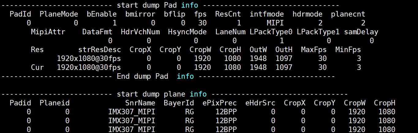
Parameter Description
Parameter Description Pad info Padid Sensor pad id Planemode Planemode switch bEnable Sensor enable bmirror Mirror bflip Flip fps Frame rate ResCnt Resolution count supported by Sensor Intfmode Interface mode Hdrmode Hdr hw mode Planecnt Plane channel count Mipiattr Datafmt Data format, yuv/rgb HdrVchNum HDR virtual channels number supported by Sensor HsyncMode 0: Synchronize last item
1: Synchronize hsync signal of next lineLaneNum The number of signal lines that support simultaneous data transmission LPackType0 Data package format 0 LPackType1 Data package format 1 samDelay Delay skipping the data header part BT656Attr BitSwap Data arrangement direction ClkEdge Sample clock mode Multinum Multimode number HPol H sync polarity PcPol Pclk polarity VPol V sync polarity HDelay H sync delay VDelay V sync delay PcDelay Pclk delay ParallelAttr HPol H sync polarity PcPol Pclk polarity VPol V sync polarity HDelay H sync delay VDelay V sync delay PcDelay Pclk delay Res Resolution info supported by Sensor strResDesc Resolution CropX/CropY/CropW/CropH Crop parameter OutW/OutH Output width/height MaxFps/MinFps MaxFps/MinFps Cur Current used resolution info Padid pad id Planeid Plane id SnrName Sensor name BayerId Bayer id ePixPrec Pixel precision (12bpp,10bpp ….) eHdrSrc HDR channel id CropX/CropY/CropW/CropH Crop parameter
5.2. echo
Echo help can view available commands:
# echo help > /proc/mi_modules/mi_sensor/mi_sensor0
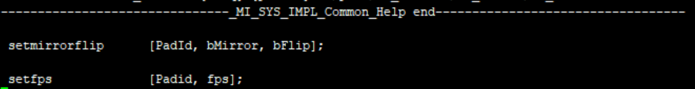
| Function | Set sensor mirrot/flip. |
|---|---|
| Command | echo setmirrorflip [PadId, bMirror, bFlip] > /proc/mi_modules/mi_sensor/mi_sensor0 |
| Parameter Description |
PadId: pad id bMirror: Mirror bFlip: Mirror |
| Example | echo setmirrorflip 0 1 0 > /proc/mi_modules/mi_sensor/mi_sensor0 |
| Function | Set sensor frame rate. |
|---|---|
| Command | echo setfps [Padid, fps] > /proc/mi_modules/mi_sensor/mi_sensor0 |
| Parameter Description |
PadId: pad id fps: frame rate |
| Example | echo setfps 0 15 > /proc/mi_modules/mi_sensor/mi_sensor0 |
6. MODPARAM INTRODUCTION
6.1. json file sample
{
    "E_MI_MODULE_ID_SNR" :
    {
        "bEnMonitor":  [0,0,0,0],
        "SnrExternalConfig": "/config/sensor_v3.json"
    }
}
modparam.json file is under /config, parameters under section "E_MI_MODULE_ID_SNR" will be loaded when sensor initialize.
modparam.json could only fill parameters which you need, others will be default value inside MI sensor.
6.2. Sensor parameters and description
| Parameters | Default | Support platform | Customer configuration | Function |
|---|---|---|---|---|
| bEnMonitor | 0,0,0,0 | All Chip | Y | Configure Sensor Monitor thread switch |
| SnrExternalConfig | "/config/sensor_v3.json" | All Chip | Y | Json file path which configure sensor hardware attributes |