ISP API Tuning SOP
REVISION HISTORY
| Revision No. | Description |
Date |
|---|---|---|
| 1.00 (API Ver 1.0) | 04/25/2024 | |
| 1.01 (API Ver 1.0) | 04/21/2025 |
OVERVIEW
Module Description
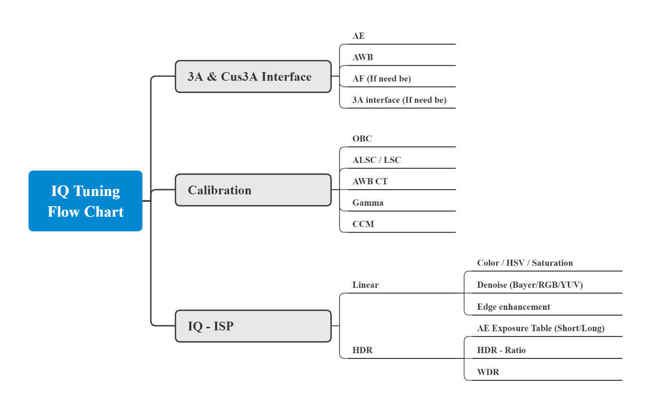
The ISP module aims to analyse and process data inputted from video source, set up associated video parameters, and perform camera tuning to realize various functions such as black level correction, lens correction, 3A and 2D/3D noise reduction, CCM, and Gamma.
Flow Chart
CONNECTING TO THE IQ TOOL INTERFACE
IQ Tool Interface Connection
-
Set up the EVB network function and enter the following command at the terminal:
#ifconfig eth0 hw ether 00:xx:xx:00:00:01

#ifconfig eth0 up

#udhcpc

#mixer -n 1 -q
Wherein, -q means turning on iqserver, which allows IQ Tool to be connected.
-
Select product type:
-
IP Camera;
-
Car Camera.
-
-
Input the IP address of the EVB.
-
Click the Connection icon (
 ) to establish the connection. If the icon is changed to (
 ), which means connection done successfully, then you can start using the tool to adjust image parameters. If you click the icon () once again, it will change back to (), and the connection will be disconnected. An illustration of the setup steps is shown in Figure below.
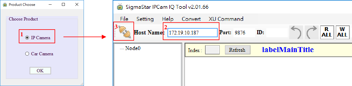
IQ TOOL INTERFACE FUNCTION DESCRIPTION
IQ Tool Interface
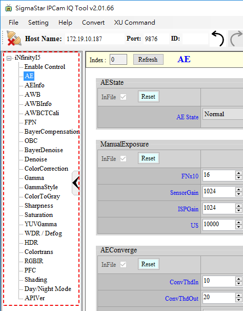
As displayed in the following figure, the functions encircled in red dotted line to the left of the IQ Tool interface compose a tree structure, each node being itself an API collection. Clicking on a node will generate the interface on the right. If you click the node AE, for example, the associated API — ManualExposure, in this case — will be automatically unfolded on the right. You can then adjust the API settings in real-time with this interface.
Parameter Tuning
Different APIs have different types of parameter setting methods, for example filling in values, selecting items in drop-down menu, reading values, creating tables, etc. Depending on the initial setting of the APIs, some grant read and write access, and others grant read-only access.
Parameter tuning:
-
Value: The value can be modified by the following three methods:
- Click the up/down arrows to adjust the value
- Fill in the value in the associated field
- Move the scroll bar leftward/rightward to adjust the value
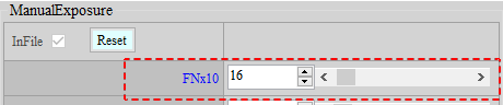
Value-type parameter tuning will have a prescribed range for adjustment, with min/max value set according to the API’s initial setting. Take ManualExposure as an example, the min. value of FNx10 is 10 and the max. 220. If the value filled in is smaller than 10, the tool will auto-correct it to 10; if the value filled in is greater than 220, the tool will auto-correct it to 220 (see the figure below).
-
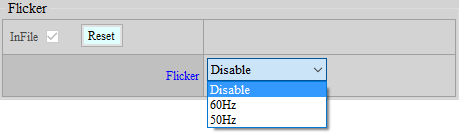
Drop-Down Menu: By clicking on the down arrow, you will see the drop-down menu with options for you to choose from. For example, in the API AE – Flicker shown in the figure below, you can select Disable, 60Hz, or 50Hz as the value for the Enable field.
-
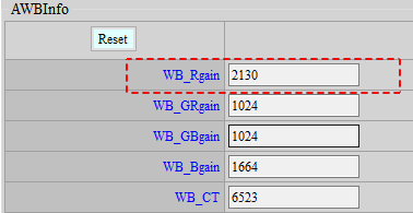
Reading Values: The value shown in this type of parameter setting is read-only and non-writable. Take API AWBInfo in the figure below as an example, the value of 2130 shown in the field of WB_Rgain can be read but not written.
-
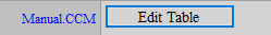
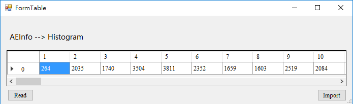
Form: A button is provided on the API, for example the button of Edit Table shown in the figure below.
By clicking the button, you will see a form window (Pop-up Window in the figure below, with a Table inside the window). Click “Read” to read the value from the platform, and “Write” to write the value to the platform.
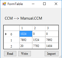
If the table is read-only, write to the platform will not be permitted by API, then only the Read button will be shown (see the figure below).
Read/Write Data
You can read/write data of the entire API collections, or all API data under the current page. Let’s take the case shown in the figure below, where the current API page is AE, as an example. If you click “Read Page” on the upper right, all data under the current AE page will be read out; if you click “Write Page” on the upper right, all data will be written into the current AE page. On the contrary, if you click “R ALL” button, all data of the entire API collections, not just those of the API AE, will be read out; if you click “W ALL” button, all data will be automatically written into the entire API collections, except those concerned with Gamma/Calibration. For Gamma, you must manually select “Write Page” to enable data to be written to the API. Table 1 shows details on the icons used for data read/write.
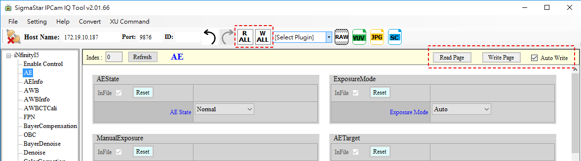
Table 1: Description of Read/Write Data Icon
| Icon | Function | Description |
|---|---|---|
 |
Read data from all API collections | Click R ALL will read data of all API collections |
 |
Write data to all API collections | Click W ALL will write data to all API collections (except Calibration) |
 |
Read data from current page | Click Read Page will read all API data under the current page. |
 |
Write data to current page | Click Write Page will write data to all API under the current page. |
 |
Write data from the current page to API in real-time | When checked, Auto Write function will become enabled. |
Saving Images in RAW/YUV/JPG Format
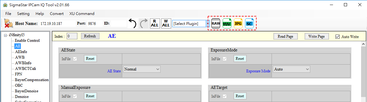
Once the platform is connected, you can click the buttons encircled in red dotted line to capture images in four formats.
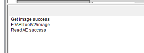
When the capture starts, a new window will pop up and display the progress. If the image is captured successfully, a success message will be shown, as illustrated in figure below, together with the directory where the image is saved. The default path is the “./Image” folder under the directory where the program exists.
Create, Save, and Load Parameters
During the tuning process with IQ Tool, you can save the parameters of the current page to a specified directory or load any parameter files already saved at any time.
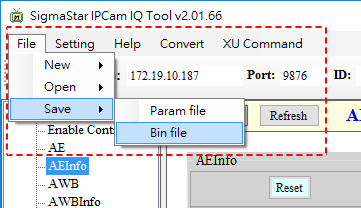
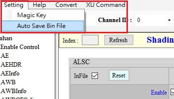
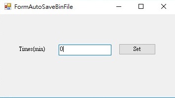
IQ Tool can save Bin File automatically. The unit of the parameter is minute, and 0 means no automatic saving. The Bin File will be saved in “CvtXml” folder. If saving is done manually, the seconds will be counted again.

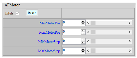
You may save API bin files without their respective API functions by simply unchecking the InFile box of the corresponding APIs, as shown in the following figure.
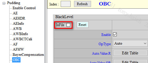
If the InFile box is locked and greyed out, and you need to save the modified API into the API Bin file, you may go to Api.xml and change the FileMode of that API to W.

-
Two formats are available for saving parameter files: XML and BIN
- XML Format
XML is mainly used for saving GUI interface (including interface parameters) of the tool.
-
BIN Format
BIN is for saving API parameters only. You can call MI_ISP_API_CmdLoadBinFile (MI_U32 Channel, char* filepath, MI_U32 user_key) at the application layer to automatically load API parameters.
-
Magic Key: can be used to verify if the bin file matches the device. The Magic Key can be set up via the Setting page. Subsequent to the API parameters of the bin file, the Xml file of the corresponding serial port will be added to ensure Xml file matches the API parameters.
-
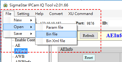
Three formats are available for loading parameters: XML, BIN and BIN XML.
-
XML Format
XML is used for loading GUI interface (including interface parameters) of the tool.
-
BIN Format
BIN is used for loading API parameters.
-
BIN XML
BIN XML is used for loading API parameters and adding the Xml of corresponding serial port.
-
CALIBRATION
OBC
The Basic Principle of OBC
During the process of data collection by CMOS sensor, the precision of ADC chip might not be high enough to convert the extremely weaker part of the signal. On account of this, a fixed amount of offset should be added before ADC input so that details in darker areas can be properly retained, despite the fact that details in bright areas may be partially lost.
The OBC module aims to establish a specific amount of offset through calibration. (Return to IQ Tuning Flow Chart)
Requirements for Grabbing RAW Images
If the sensor does not come with optical black parameters, or more precise parameters are required, the client will need to perform black level correction. The work flow of grabbing RAW images for the correcting purpose is set out as follows:
A. Cover the lens completely with lens cap and make sure that there is no light leak. If the lens comes with a variable aperture, the aperture should be completely closed to ensure that no light will leak into the chamber.
B. Grab RAW images at 1X gain and at the maximum gain by following the steps below (Note: If the results vary greatly, you will need to grab multiple sets of RAW images). First, set AE to M_Mode, and then set SensorGain/ISPGain/US in ManualExposure; after that, go to the AEInfo module and check if AE is written correctly.
C. Grab RAW file by using API TOOL.

OB Correction Steps
-
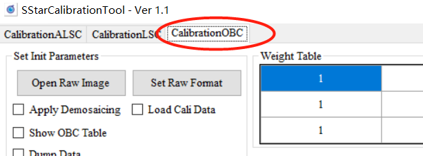
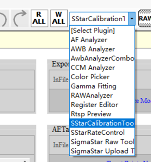
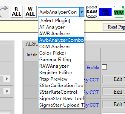
Select “SStarCalibrationTool” from the Plugin menu, and then click the tab “CalibrationOBC”.

-
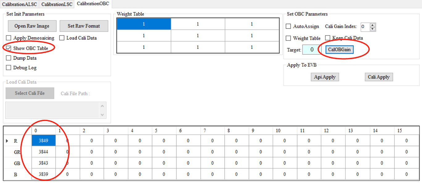
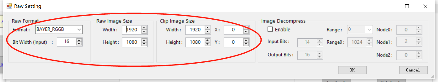
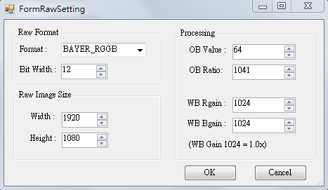
Click “Set Raw Format” and set corresponding information according to the RAW file.

-
Click “Open Raw Image” (Note: no Chinese character is allowed in the name of file folder), check “Show OBC Table,” and then click “CalOBGain” on the right.
Analysis of the Correction Result
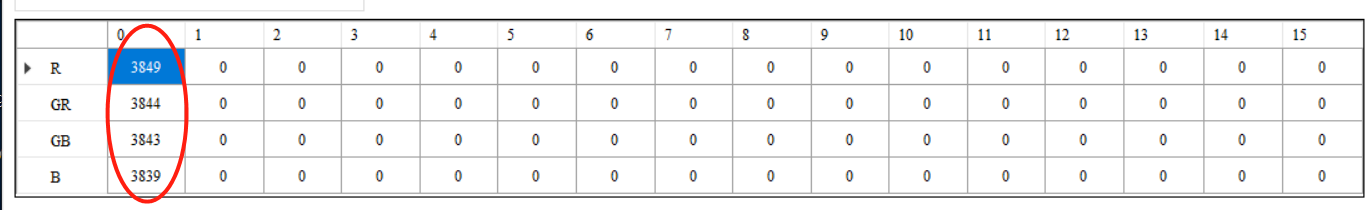
Column 0 represents the calibration result, which is ready to be filled into the OB module. If the difference between calibration results under each gain is smaller than 50, calibrating one set of RAW images will do.
ALSC
The Basic Principle of ALSC
There are two kinds of shading in general: lens shading and color shading. A brief description of the difference between the two is set out below:
Lens Shading:
-
Due to the optical characteristics of lens, the intensity of light received by the sensor on the margin is weaker than that in the center, resulting in uneven brightness in the center and around the corners (also known as the dark corner) in the picture.
-
The chief ray angle (CRA) of the lens is not compatible with the sensor, resulting in insufficient exposure received by the sensor in marginal region.
Color Shading:
-
The incident angle on the margin of the lens is not big enough, which causes color deviation (chromatic dispersion). This phenomenon is often manifested by the inconsistency of color between the center and the margin.
-
Due to the different frequency spectrum of diverse light sources or color temperatures, and aggravated by the impact of IR-cut, colors often appear to be uneven.
On account of these issues, shading calibration should be performed upon such lenses with severe shading problems (including both lens shading and color shading issues) before proceeding to AWB calibration. (Return to IQ Tuning Flow Chart)
Requirements for Grabbing RAW Images
- Aim the lens at the screen of a DNP standard color viewer lightbox and make sure that illumination is even. If DNP standard color viewer is not available, you may also cover the lens with a piece of frosted glass and aim the lens at the light source of a standard lightbox.
- Set the brightness of lightbox, or you may also adjust AE target. The brightness in the center of the picture should be around 70 percent of the maximum brightness. You may inquire the brightness by using imageJ to select the center of the RAW image.
- Grab the RAW file.
Calibration Flow for ALSC
-
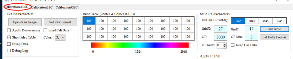
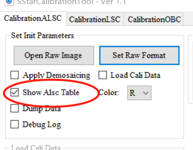
Select “SStarCalibrationTool” from the Plugin menu, and then click the tab “CalibrationALSC”.
-
Click “Set Raw Format” and set corresponding information according to the RAW file.
-
Click “Open Raw Image” (Note: no Chinese character is allowed in the name of file folder), check “Show ALSC Table”.
-
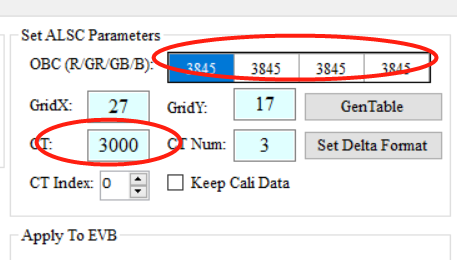
Set corresponding OBC parameters, as well as the color temperature parameters.
-
Click “GenTable” to start calibration.
Analysis of the Correction Result
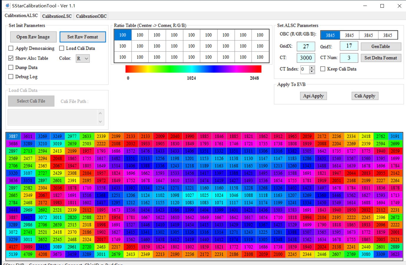
The figure above shows an example of the calibration result. Now, select the corresponding color temperature (CT) and CT Num, click “API Apply” to apply the data to the connected EVB. After that, go to the ALSC module and click “read page” to load calibration parameters so as to save them in the tool.
Note
After clicking “API Apply”, make sure you go to the ALSC page and click “read page” so that calibration parameters are properly saved in the tool.
AWB
The Basic Principle of AWB
AWB calibration aims to calculate the R/G and B/G gains in real-life scenarios based on the characteristics of white spots presented by the sensor under various standard light sources. (Return to IQ Tuning Flow Chart)
Calibration Flow for AWB
- Aim the lens at the grey card inside a standard lightbox, and the grey card should fully occupy the picture.
- Set the color temperature that needs to be calibrated (including standard light sources such as D65/D50/TL84/CWF/U30/A, depending on the lightbox).
- Make sure that OBC and its setting has been done.
- Set AE to Auto, and adjust AE Target to prevent the picture from being overexposed.
-
Select “AwbAnalyzerCombo” from the Plugin Menu.
-
Select the range of color temperature to be calibrated. We recommend setting the range from 2300K to 10000K.
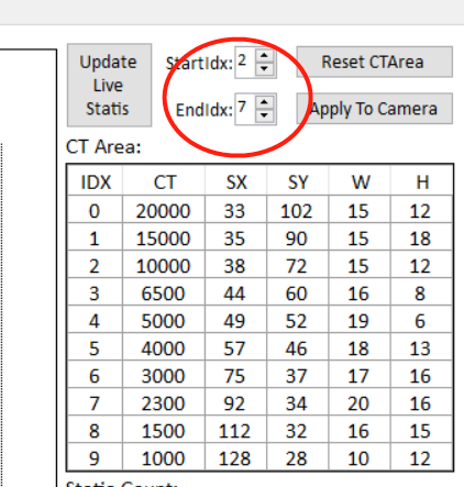
-
Drag and move the red triangle markers or the blue lines so that all statistics are able to fall into their corresponding ranges, making the curve line as smooth as possible.
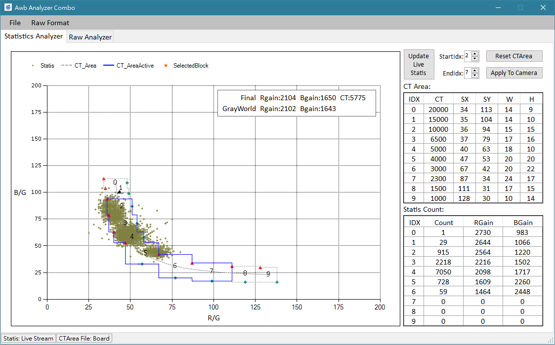
-
Adjust multiple color temperatures. When all adjustments are made, click “Apply To Camera” to apply the changes to the board and check the effects.
- Go to the AWBCTCali module and read page, and save the parameters.
Note
After calibration is finished, you should test the AWB effect under various scenarios, calibrate the size of the adjustment frame accordingly, and make sure the AWB remains stable in every scenario.
CCM
The Basic Principle of CCM
The calibration principle of CCM is to obtain a 3x3 color correction matrix by calculation, which is based on the actual data of colors in a standard color checker (of 24 colored squares) as photographed by the sensor under different color temperatures, along with the data of target color. The ultimate goal is to calibrate the output colors of camera to meet our expectation. (Return to IQ Tuning Flow Chart)
You must determine gamma before starting CCM calibration. To calibrate the gamma closer to that of the reference model, please refer to Gamma Fitting.
Requirements for Grabbing RAW Images
- Place the colorchecker inside the standard lightbox, aim the lens at the chart and make sure the chart is situated in the center of the picture and occupying 50 to 80 percent of the entire picture.
- Set color temperature of the lightbox. Normally, we would set it to the temperature of D65/TL84/A.
- Adjust the brightness of light or fine-tune AE target so that the 19th grid of the RAW image is not overexposed.
- Grab RAW data by using API Tool.
Calibration Flow for CCM
-
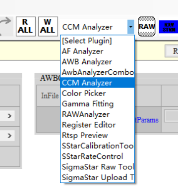
Select “CCM Analyzer” from the Plugin menu, and then click the tab “Calculate CCM”.
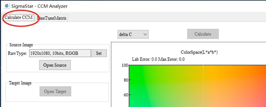
-
Set corresponding information according to the RAW file.
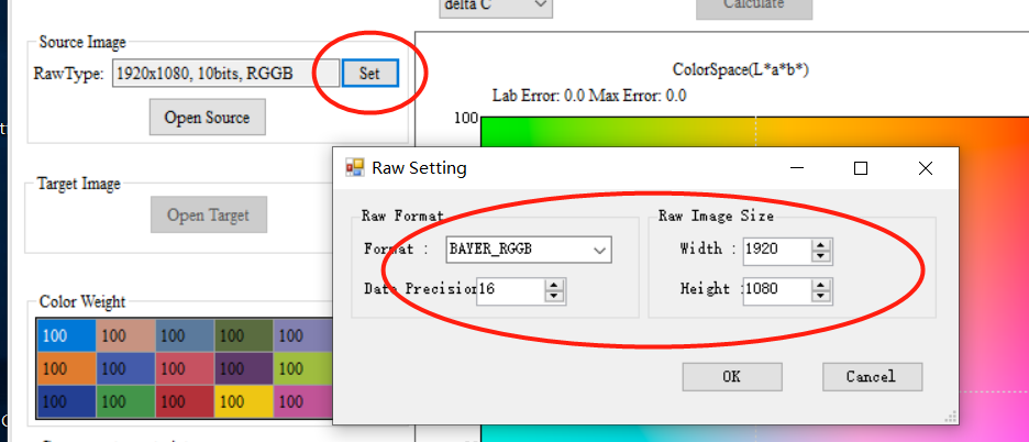
-
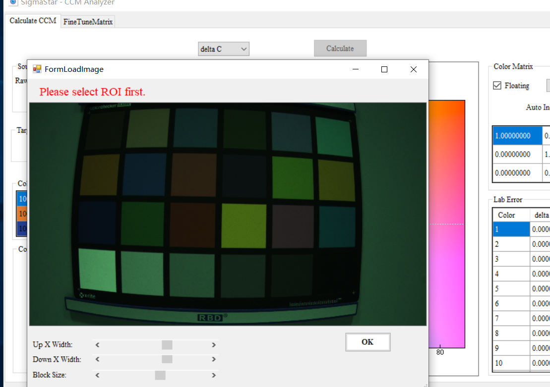
Click "Open Source" to open the corresponding RAW image, then click the left button and drag the frame to select the color checker.
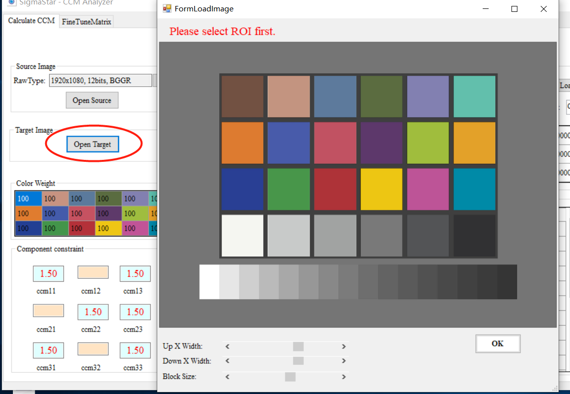
-
Open Target allows you to designate the target color checker. apitool → target_img provides the standard color checkers.
-
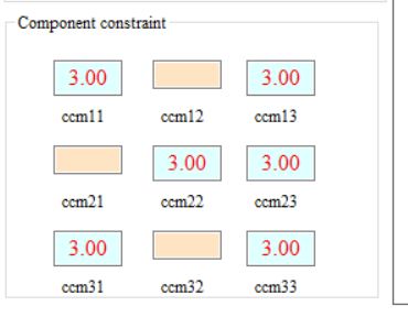
Adjust component constraint.
-
Click “Calculate” and start calibration calculation.
-
Uncheck the box of “Floating”, select the group of interpolation, and apply the calibration result to the device.
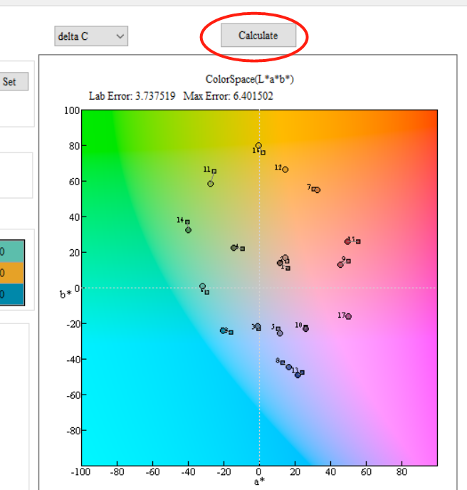
Analysis of the Correction Result
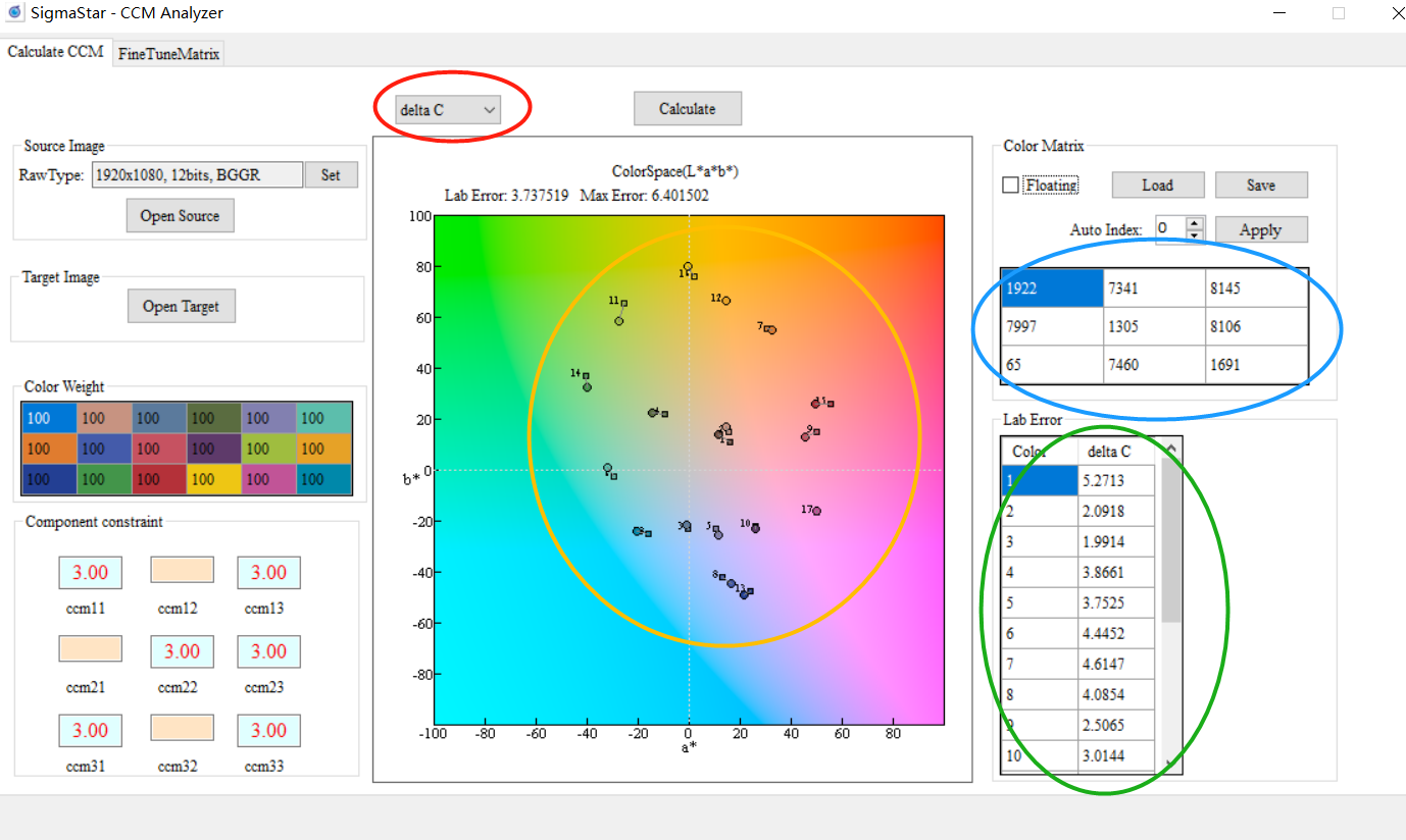
-
Frame in yellow: The round points represent the standard points, while the square points represent the falling points of color after calibration. This design helps you visualize the extent of color deviation.
-
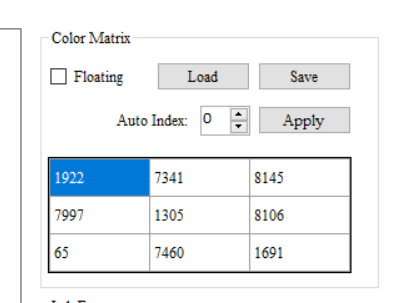
Frame in blue: Shows the CCM matrix of calibration result.
-
Frame in green: Shows the color deviation value of each color. The smaller the value, the smaller the difference from standard color checker.
Note
In case that calibration result is not satisfactory, you may manually adjust CCM parameters to achieve the desired effects. Due to different lens and sensor characteristics, high precision and complete calibration accuracy might be very difficult to achieve in certain modules by CCM alone. In this case, you may resort to HSV to fine-tune certain color presentations.
AE Exposure Table Setup
Different sensors and lens have different characteristics and capabilities, so the default AE exposure table is not necessarily suitable for the module currently in use. Here, we suggest that you check AE exposure table and modify the setting, where necessary, to fit the current module.
Adjustment Interface
Select AE from the menu on the left-hand side, then click “ExpoTblEntry”. An adjustment interface will pop up for editing AE exposure table.
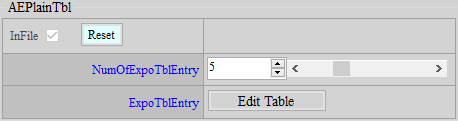
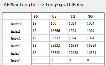
Parameter Description
NumOfExpoTblEntry: The number of AE exposure table. Let’s take AE Adjustment Interface as an example, as the number of AE exposure tables is set to 5, you should fill out 5 sets of AE exposure table correspondingly.
First Column (FN): Lens aperture value (Fn) x 10. For example, if aperture is 1.6, the value will be 16.
Second Column (US): Shutter (usec)
Third Column (TG): Total gain (1024 = x1 gain), i.e. sensor gain x ISP gain
Fourth Column (SG): Sensor gain (1024 = x1 gain)
Setting Items
- Check the lens aperture value, multiply by 10 (lens aperture value x 10) and fill in the result in the first column.
- Verify the maximum gain with customer, and fill the value in the third column of the last row.
- If ISP gain is not used, copy the value in the third column to the fourth column.
GAMMA FITTING & COLOR CORRECTION
Different gamma and colors have different impacts on noise. Besides, denoise adjustment will be much easier if you apply gamma and color settings beforehand. Therefore, gamma and color corrections are normally done first even when their place come after denoise in the pipeline.
Gamma Fitting
Color fitting result is susceptible to differences in brightness, and such difference mainly comes from AE and gamma. As such, it is imperative that gamma fitting should be done before color fitting. This step aims to fit the gamma of the calibration model closer to that of the reference model. Before calibration, make sure the dynamic range is set to full range. (Return to IQ Tuning Flow Chart)
Calibration Environment
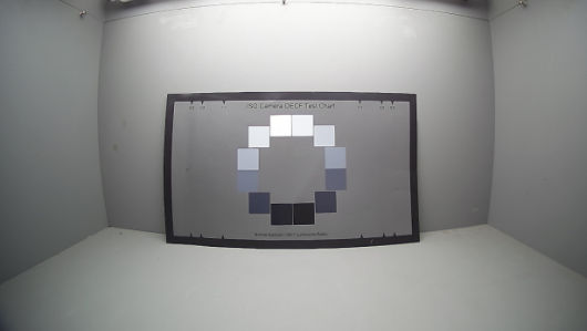
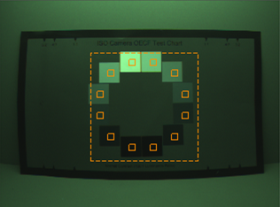
Prepare an OECF chart and have light illuminated evenly on the chart. Place the chart in middle of the screen when shooting; do not occupy the whole screen with the chart, otherwise the result might be affected by shading.
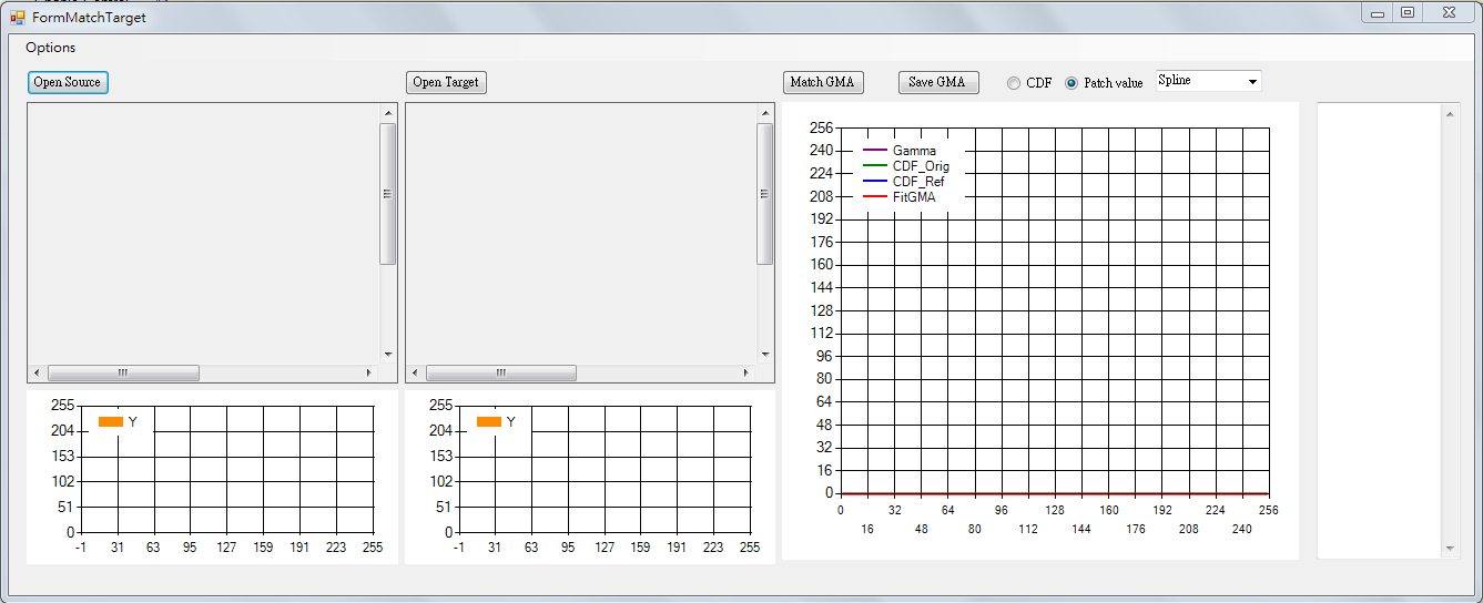
Calibration Interface
Click “Select Plugin” on the top of API, and select “Gamma Fitting” to open the calibration interface.
Calibration Flow
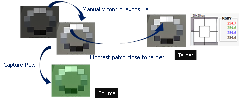
-
Set up the environment, and shoot images required for fitting between calibration model and reference model. Since exposure may affect brightness, the gamma fitting should be performed based on the same exposure setting. The easiest way to obtain the closest exposure is to set the brightest patch of the OECF chart as close as possible (but not equal) to 255 when capturing images (RAW for calibration model and JPG for reference model). The logic is that, while we do not know about the gamma of reference model, the brightest patch usually remains unchanged, which makes it a suitable candidate as the base for fitting.
-
Read the OECF patch value of source RAW data: Select “Options” from the menu of the interface tool, fill in the correct RAW information and OB (WB not required), and click OK.
Drag-select OECF patch with your mouse. Be sure each patch is correctly located within the patch location.
-
Read the OECF patch value of target image:
The same as the preceding step; the only difference in this step is that the target reads the image file without setting RAW information.
-
Set parameters related to fitting. We suggest setting “Patch values” as the method of getting value, and “Exponential” as the fitting method.

-
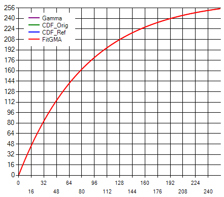
After setup, click “Match GMA” to start gamma fitting. If nothing abnormal is found with the curve generated by fitting, click “Save GMA” to save the gamma curve. Finally, check to see whether the start and end of the saved gamma curve fall at 0 and 1023, respectively. If not, modify them manually.
Color Correction
The main purpose of this step is to bring the color of the calibration model close to that of the reference model. Color correction involves two parts: the first (and also the most important) part is the fitting of color matrix; the second part is HSV fine-tuning, which allows you to adjust local color saturation and hue according to your preference. Color matrix and HSV each support up to 16 sets of color temperatures. Index0 to Index15 represent color temperatures from low to high. Be sure to follow this rule when filling in the parameters. (Return to IQ Tuning Flow Chart)
CCM Adjustment
After finishing calibration of light sources of various color temperatures with the tool, be sure to fill in the results manually in the corresponding fields of color correction matrix (CCM).
If you want to turn off this IP, go to the Enable Control page and click Disable.
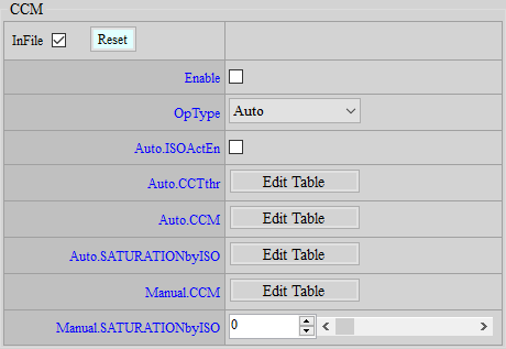
Adjustment Interface

Parameter Description
ISOActEn: Enables/Disables the function to automatically set CCM as the unit matrix in Night mode. If enabled, CCM will be automatically switched to the unit matrix when IQMode is Night.
CCTthr: Color temperature node setting. The color temperature value obtained at the time of CCM calibration needs to be filled in. CCM and HSV will refer to this CCTthr to determine which node setting to apply. Index should be filled from small to large and follows the sequence of low-to-high color temperature. 16 sets of nodes at most are supported. For nodes not used, set them to 0.
CCM: Color matrix setting of each color temperature. Corresponding color matrix should be filled in according to color temperature. Index should be filled from small to large and follows the sequence of low-to-high color temperature.
SATURATIONbyISO: Adjust the saturation of color matrix. The program will perform an interpolation based on this setting between user-defined matrix and unit matrix. Parameter range: 0 ~ 100. 0 means using unit matrix, and 100 means using user-defined CCM. This parameter is switched by the gain value.
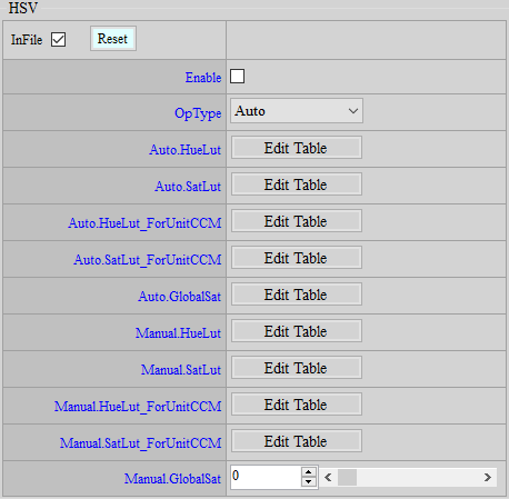
HSV Adjustment
You may use HSV adjustment to further fine-tune certain colors after having applied color correction matrix (CCM). HSV will divide the entire color domain into 24 segments. You may adjust different hues and saturation in relation to each other according to the needs arising from various scenarios. The parameters of HSV are the same as CCM, which are switched according to color temperature rather than gain.
If you want to turn off this IP, go to the Enable Control page and click Disable.
Adjustment Interface
Parameter Description
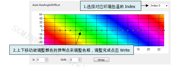
HueLut : Adjust hue in certain regions. Parameter range: -64 ~ 64. 0 means no adjustment.
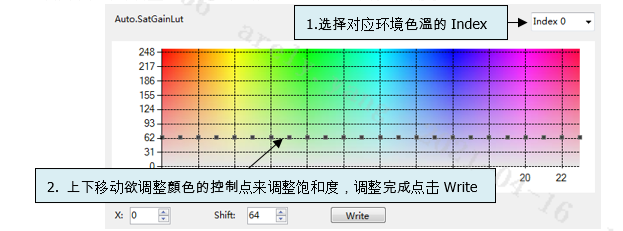
SatLut: Saturation can be adjusted locally as needed. The value range is 0~255, and 64 means no change.
HueLut_ForUnitCCM: Hue adjustment with unit matrix. The value range is -64~64, 0 means no change, parameter switching is based on color temperature.
SatLut_ForUnitCCM: Adjust the hue of the unit matrix. The value range is 0~255, 64 means no change. The parameter switching is based on the color temperature.
GlobalSat : Adjust the overall color saturation. The value range is 0~255, 64 means no change, and the parameter is switched based on gain. It is recommended to use this to reduce the saturation, which is more effective in reducing the noise level, and to use the Saturation API to increase the saturation, which will not increase the noise level.
Saturation Adjustment
UV adjustment based on brightness (Y) and saturation (UV) includes “Adjust UV by Y” and “Adjust UV by UV”. Such function mainly aims to reserve color adjustment flexibility in YUV domain. Besides, since brightness and saturation are independent of each other, you can maintain a fixed brightness while making partial saturation adjustment. When high exposure values are applied to sensor, you can lower the color noise in dark area, or increase/decrease the saturation according to user preference, to make the picture look brighter or softer.
If you want to turn off this IP, go to the Enable Control page and click Disable.
Adjustment Interface
Select “Saturation” from the menu on the left-hand side, and Saturation Interface will pop up on the right.
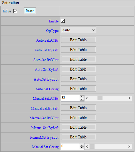
Parameter Description
Sat.AllStr: Variable strength of global saturation. Parameter range: 0 ~ 127 (32 = 1x).
Sat.ByYsft、Sat.BySsft: Adjust the spacing of X-axis of UV by Y/UV with special limitation to be observed, as stated below:
The nodes are a power of 2 and add up, for example: Sat.ByYsft[5] = {3, 3, 5, 7, 7}
Suppose the first node is 0, the second node will be 0+2^3, the third 0+23+23, the fourth 0+23+23+2^5, and so forth;
Then the spacing of nodes on X-axis will be {0, 8, 16, 48, 176, 255}, where the last node is greater than 255.
The limitation is that, the sum of the first four X-axis nodes must be less than 255, while the last node should be greater than or equal to 256.
For example, if Sat.ByYsft[5] = {8, 0, 0, 0, 0}, with the first node being 0 and the second 0+2^8=256. This would go against the limitation above.
Sat.ByYLut, Sat.BySYLut: Determines the values of node freely.
Special application: If HDR function is enabled and causes oversaturation in high brightness part, you may suppress UV of high brightness or high saturation by using Sat.ByYLut or Sat.BySLut, so that the picture would look more natural under HDR effects.
![Sat.ByYsft[5] & Sat.ByYLut[6]](mymedia/iqtuning/iq-37.png)
![Sat.BySsft[5] & Sat.BySLut[6]](mymedia/iqtuning/iq-38.png)
DENOISE & EDGE ENHANCEMENNT
Default parameters in iqfile will be loaded to the interface when platform is connected to API tool. However, whether each IP is enabled or disabled is not displayed on the interface. If you want to adjust the image quality of a new sensor from scratch, we suggest that you go to Enable Control interface first to bypass all functions except Sharpness API and those that have been previously adjusted (OB, ALSC, Gamma, and Color). This way, you will have a general understanding of the sensor before any denoise adjustment, such as the maximum resolution supported and whether crosstalk or false color exists. After that, enable the functions according to your need for further adjustment so as to avoid other functions unnecessarily affecting the overall image quality. Theoretically, Sharpness API should also be bypassed, but we still recommend that you keep Sharpness API enabled for the convenience of observation and hold onto default values (you might set OverShootGain or UnderShootGain smaller at higher gains) to keep the picture stable.
Adjusting high gains with Sharpness API enabled but denoise disabled will lead to much noise in the picture that it becomes difficult to examine the effect of adjustment. We suggest that you set Y.TF.STR to stronger strength to stabilize picture for the convenience of adjusting other functions before NR3D. The adjustment should be done following the sequence of ISO index. To prevent parameter interpolation from affecting your judgement, we suggest setting AE to Manual SV mode and assigning specific gain value to each node. Only after finishing one should you move on to the next. Before adjusting image quality, be sure you clean the lens and keep it focused, and also make sure that the IR cut of RGB sensor is properly caped.
Crosstalk & False Color Adjustment
Before moving forward to denoise adjustment, check if there is any fixed pattern, cross talk or false color. Correct it when any of such phenomena exists. For one thing, these functions come before denoise in the pipeline; for another, special phenomenon can only be resolved effectively with specific function. Any attempt to remove these phenomena by denoise might impair the image quality.
Crosstalk (Green Equal)
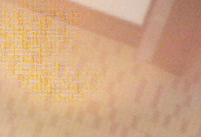
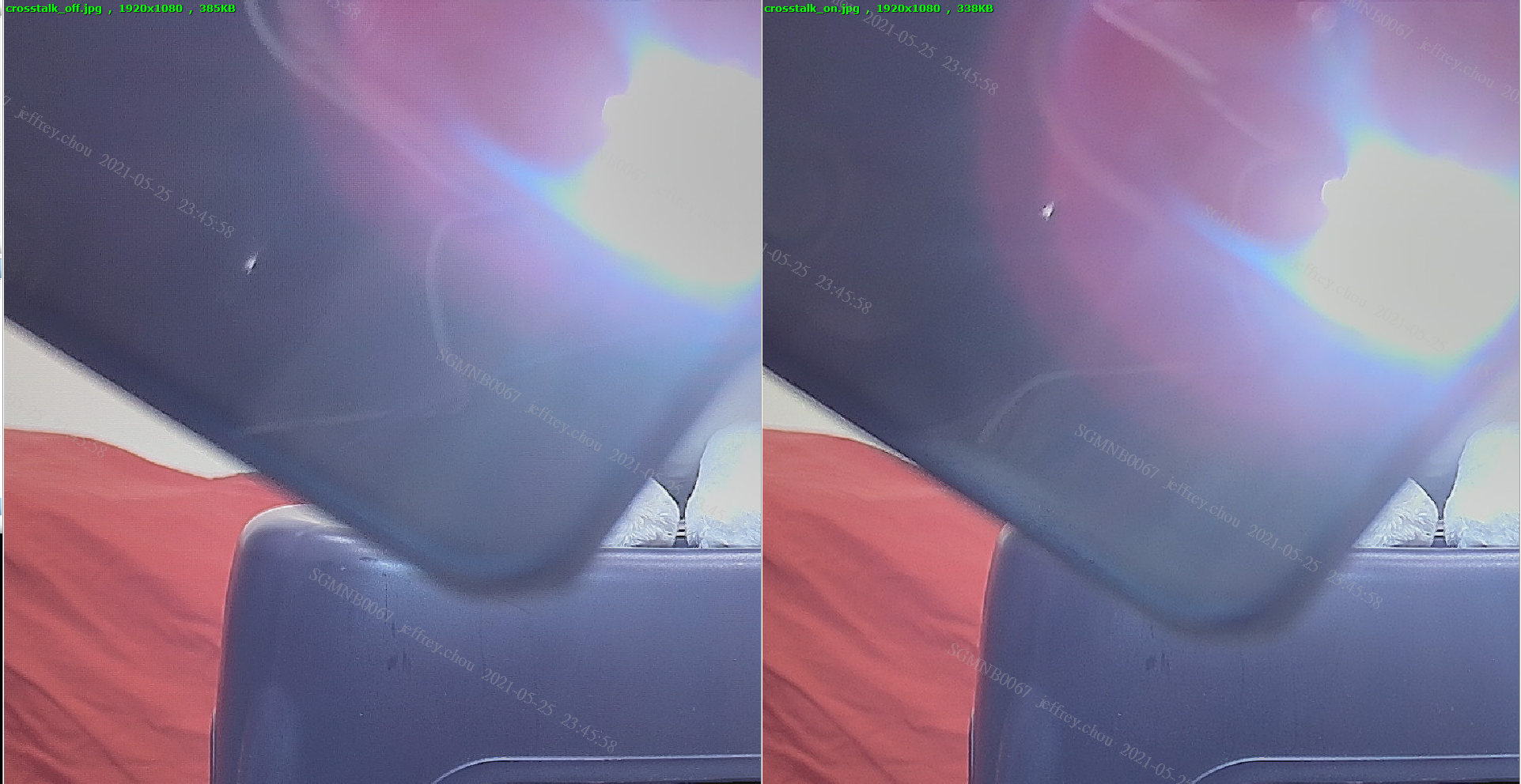
Crosstalk is primarily an issue of lens and sensor compatibility. When light enters the micro lens on the sensor at large angles, the signal supposed to be received by certain pixel might be mistakenly received by neighboring pixels, giving rise to greater Gr-Gb difference. This issue tends to occur at the corner of a picture or when the light enters at a certain angle.
If you want to turn off this IP, go to the Enable Control page and click Disable.
Phenomenon
Adjustment Interface
Select “BayerCompensation” from the menu on the left-hand side, and Crosstalk Interface will pop up on the main screen to the right.
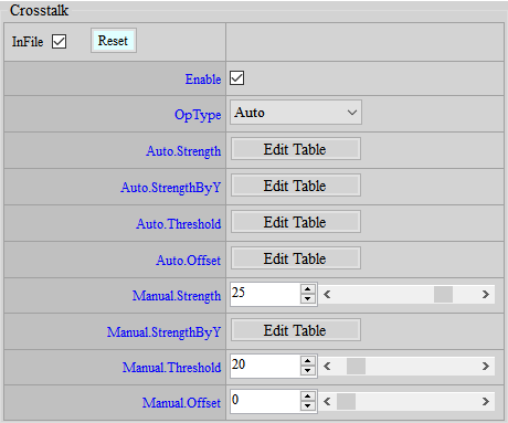
Parameter Description
Strength: Crosstalk strength. Parameter range: 0 ~ 31. The greater the strength, the stronger the effect.
StrengthByY: Adjust crosstalk strength value by Y. The closer to the right end of the horizontal axis, the brighter. Parameter range: 0 ~ 127. The greater the strength, the stronger the effect. “64” means no change.
Threshold: The value of crosstalk threshold ratio. Parameter range: 0 ~ 255. The greater the value, the wider range of action.
Offset: The value of crosstalk threshold offset. Parameter range: 0 ~ 4095. The greater the value, the wider range of action.
Adjustment Flow
- Set Offset to 0 and Threshold to 128, increase Strength from 0 and observe the region where crosstalk needs to be removed and the region where the details should be maintained. Stop when both crosstalk and details are acceptable.
- Use Threshold if further fine-tuning is required.
- If crosstalk is still obvious in dark region, increase Offset.
Example: CrossTalk Disable/Enable
False Color
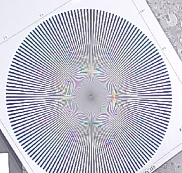
False color arises in cases where direction is not considered or misjudged during demosaic process. This phenomenon is likely to occur in high-frequency regions or at the edge of a picture.
If you want to turn off this IP, go to the Enable Control page and click Disable.
Phenomenon
False color occurs in high-frequency regions or at the edge of a picture.
Adjustment Interface
Select “BayerCompensation” from the menu on the left-hand side, and AntiFalseColor Interface will pop up on the main screen to the right.
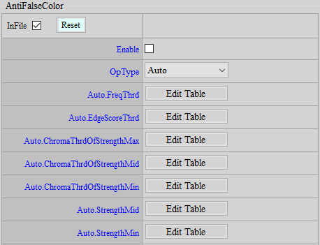
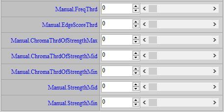
Parameter Description
FreqThrd: Frequency threshold. The value range is 0 ~ 255, the smaller the value, the easier it is to make false color.
EdgeScoreThrd: Edge score threshold. The value range is 0 ~ 255, the larger the value, the easier it is to make a false color.
ChromaThrdOfStrengthMax: Maximum strength threshold. The value range is 0 ~ 127. The larger the value, the easier it is for the moire area to be desaturated.
ChromaThrdOfStrengthMid: Middle strength threshold. The value range is 0 ~ 127. The larger the value, the easier it is for the moire area to be desaturated.
ChromaThrdOfStrengthMin: Minimum strength threshold. The value range is 0 ~ 127. The larger the value, the easier it is for the moire area to be desaturated.
StrengthMid: Middle strength. The value range is 0 ~ 7. The smaller the value, the less the saturation decreases.
StrengthMin: Minimum strength. The value range is 0 ~ 7. The smaller the value, the less saturation will be reduced.
Adjustment Flow
IF (freq > FreqThrd && edgeScore < EdgeScoreThrd)

    isMoire = TRUE;

ELSE

    isMoire = FALSE;
Anti-False Color uses Frequency and Edge Score to separate False Color in the high frequency area. To adjust, we can first relax these two conditions and only adjust the saturation part, and then gradually find the thresholds of the three conditions of Frequency, Edge, and ChromaThrd. If the effect is not enough or the side effects are too strong after finding all three thresholds, we can modify the thresholds of one or two of them.
-
First, set ChromaThrdOfStrengthMax to the maximum, FreqThrd to the minimum, EdgeScoreThrd to the maximum, ChromaThrdOfStrengthMid and ChromaThrdOfStrengthMin to the minimum. The screen should be completely black and white at this time.
-
Increase FreqThrd until the colors of all scenes except the False Color in the screen are basically restored to normal. Prioritize the removal of FalseColor, and the other color scenes are basically normal. Note the FreqThrd at this time.
-
Set FreqThrd back to 0, and this time reduce EdgeScoreThrd until the colors of other scenes are basically restored to normal. Again, prioritize the removal of FalseColor, and the other color scenes are basically normal. Note the EdgeScoreThrd at this time.
-
Keep FreqThrd at 0 and set EdgeScoreThrd back to the maximum; adjust ChromaThrdOfStrengthMax to reduce it to the extent that other scenes return to normal colors and the False Color can be grayed out. If both cannot be taken into account, prioritize ensuring that the colors of other scenes are normal.
-
Increase ChromaThrdOfStrengthMid to make the remaining false colors lighter, but still prioritize ensuring that the colors of other scenes are normal.
-
Increase ChromaThrdOfStrengthMin and continue to process the remaining false colors
-
Adjust ChromaThrdOfStrengthMin to be greater than ChromaThrdOfStrengthMid, and StrengthMid to be less than StrengthMin
-
Fill in FreqThrd and EdgeScoreThrd with the values recorded above
-
If the surrounding scenes still have side effects, set a large FreqThrd or a small EdgeScoreThrd to restore the surrounding scenes to normal colors.
-
If adjusting FreqThrd or EdgeScoreThrd still cannot completely avoid the side effects when reaching False Color, set FreqThrd as small as possible and EdgeScoreThrd as large as possible, then start to reduce ChromaThrdOfStrengthMax or increase ChromaThrdOfStrengthMid and ChromaThrdOfStrengthMin until no side effects are seen or the impact is acceptable.
Note:
- FalseColor will be of some help to remove thinner purple edges. If purple edges remain a serious issue after FalseColor is set to the maximum strength, you can use HSV to reduce the saturation of purple hue. During the adjustment, watch out if the saturation of normal purple object is too low.
-
Adjustment to false color is highly related to the existence of crosstalk, because strong crosstalk leads to serious false color issue, which in turn prevents false color suppression function from removing it; thus, we suggest that crosstalk tuning to be completed before the anti-false color process.
-
ChromaThrdOfStrengthMax and ChromaThrdOfStrengthMid are thresholds for different Chroma sources, so they have no dependency in adjustment. However, ChromaThrdOfStrengthMid and ChromaThrdOfStrengthMin do have a dependency, and ChromaThrdOfStrengthMid should be greater than ChromaThrdOfStrengthMin in design.
PFC (Purple Fringing Compensation)
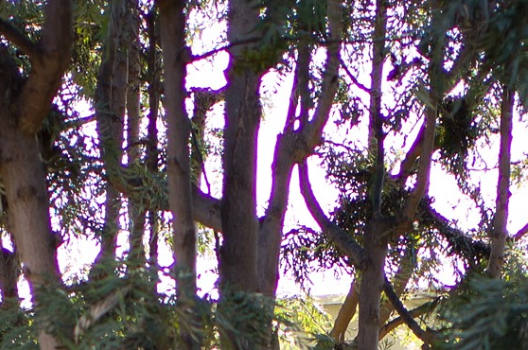
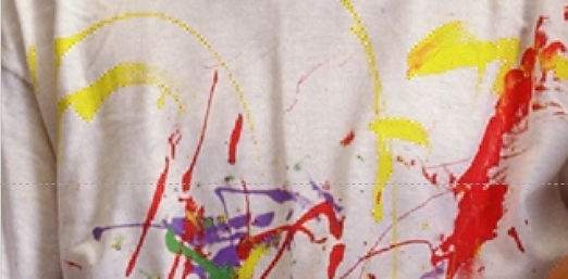
Phenomenon
Purple fringe appears in the margin edge of object.
If you want to turn off this IP, go to the Enable Control page and click Disable.
Adjustment Interface
Select “PFC” from the menu on the left-hand side, and PFC Adjustment Interface will pop up on the main screen to the right.
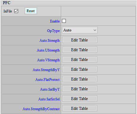
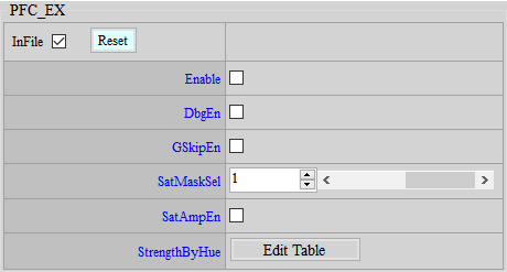
Parameter Description
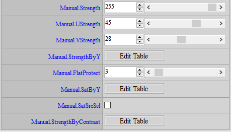
Strength: Control the intensity of the purple fringing removal. The value range is 0~255, the larger the value, the stronger it is.
UStrength: The intensity of the purple fringing removal on the U channel. The value range is 0~63, the larger the value, the stronger it is.
VStrength: The strength of the purple fringing removal on the V channel. The value range is 0~63, the larger the value, the stronger it is.
StrengthByY: Purple fringing usually appears in darker areas, surrounded by bright areas, so different strengths of purple fringing removal can be given for different brightness levels. The rightward direction of the horizontal axis represents a higher brightness. The value range is 0~255, and the larger the value, the stronger it is.
FlatProtect: Flat area judgment, to prevent large areas of purple from being judged as purple fringing, and to protect against it. The value range is 0~127, the larger the value, the more areas will not be PFC.
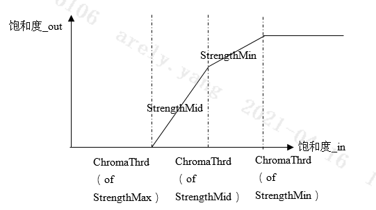
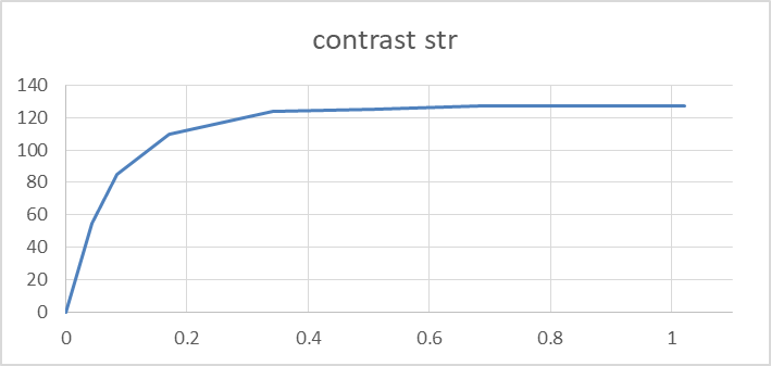
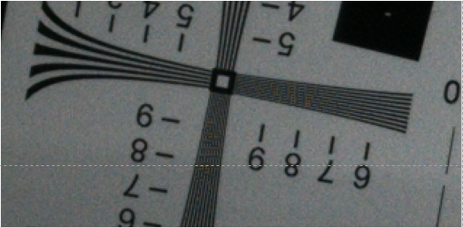
SatByY: Determination of high contrast area. Purple fringing usually occurs in areas with high contrast, so SatByY[0] is used to determine the degree of contrast. The value range is 0~25. The larger the value, the higher the detected contrast must be to exceed SatByY[0] to be considered high contrast. SatByY[1] is used to determine the degree of brightness saturation. The value range is 0~25. The larger the value, the lower the PFC for brighter areas.
SarSrcSel: When judging high contrast areas, you can choose whether to do NR pre-processing. The value range is 0~1, 0 means no NR, 1 means NR. It is recommended to turn on this function in low light conditions.
StrengthByContrast: According to the degree of contrast, different strengths of PFC are given. The further to the right of the horizontal axis, the stronger the contrast. The value range is 0~63, and the larger the value, the stronger the PFC.
DbgEn: Display the scope of PFC. The value range is 0~1, 1 means enabled.
GSkipEn: Do not perform FPC processing on G Channel to protect against some edge loss issues. The value range is 0~1, 1 means enabled.
SatMaskSel: Mask size selection for comparison area judgment. The value range is 0~1. Mask 0 has a smaller range. Mask 1 has a larger range.
SatAmpEn: When judging the contrast area, checking this function can increase the accuracy of judging the contrast.
StrengthByHue: According to different Hues, different intensities of PFC treatment are given.
Adjustment Flow
-
Determine SatAmpEn first.
-
According to the lens performance, observe the width of the purple fringing and select the size of SatMaskSel. If the purple fringing is wider, you can first use a larger mask to compensate.
-
Observe the brightness area, contrast level, and color distribution of the purple fringing to adjust StrengthByY, SatByY, StrengthByContrast, and StrengthByHue.
i. StrengthByY: Observe the brightness at which the purple fringing occurs and give a stronger setting. Generally, the darker the place, the stronger the intensity.
ii. SatByY, StrengthByContrast: Observe the contrast under which purple fringing occurs and set a stronger setting. Generally, the higher the contrast, the stronger the intensity. SatByY is used to control the landing point of the horizontal axis in the figure below, and StrengthByContrast is used to control the vertical axis in the figure below. Under low light conditions, the contrast judgment may be slightly inaccurate due to noise. You can appropriately relax SatByY[0] to prevent noise from being judged as a high-contrast area.
-
Control FlatProtect to ensure that some flat areas will not achieve the PFC effect.
-
Adjust the final PFC strength. If you have special color requirements, you can adjust the strength of Ustrength and Vstrength separately.
DEMOSAIC
Phenomenon
Reduce the misjudgement of direction and prevent artifacts from being generated when picture resolution is increased.
Adjustment Interface
Select “BayerCompensation” from the menu on the left-hand side, and Demosaic Interface will pop up on the main screen to the right.
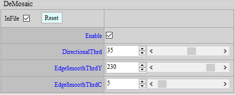
Parameter Description
DirectionalThrd: The threshold for directional interpolation or non-directional interpolation. The value range is 0 ~ 63. The larger the value, the more small details are blurred.
EdgeSmoothThrdY: Do smooth according to brightness. The value range is 0 ~ 255. The smaller the value, the less sharp the edge is and the less likely artifacts are to occur.
EdgeSmoothThrdC: Do smooth based on saturation. The value range is 0 ~ 127. The smaller the value, the less sharp the edge is and the less likely artifacts are to occur.
DynamicDP & NRDespike Adjustment
As described in the preceding section, peak noise is basically regarded as a special noise, and hence needs to be removed or weakened by a specific function. It is recommended that peak noise be handled before normal noise so as to avoid impairing the image quality in the case that other denoise functions are arbitrarily applied to dealing with peak noise. Two functions — DynamicDP and NRSpikeNR — are available for coping with peak noise, and they can be applied simultaneously.
DynamicDP (Dynamic Defective Pixel Correction)
Defective Pixel Correction (DPC) handles peak noise by replacing the problematic pixel, and hence the effect is more noticeable.
If you want to turn off this IP, go to the Enable Control page and click Disable.
Adjustment Interface
Select “BayerCompensation” from the menu on the left-hand side, and DynamicDP Interface will pop up on the main screen to the right.
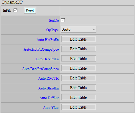
Parameter Description
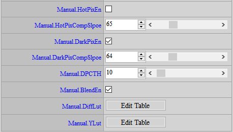
HotPixEn: Enable hot defective pixel removal.
HotPixCompSlope: Threshold value for determining if a pixel is a hot defective pixel. Parameter range: 0 ~ 255. The greater the value, the more unlikely a pixel will to be judged as a hot defective pixel, and vice versa.
DarkPixEn: Enable dark defective pixel removal.
DarkPixCompSlope: Threshold value for determining if a pixel is a dark defective pixel. Parameter range: 0 ~ 255. The greater the value, the more unlikely a pixel will be judged as a dark defective pixel, and vice versa.
DPCTH: Threshold value of defective pixel and neighboring pixels in the same channel. Parameter range: 0 ~ 255. The greater the value, the more unlikely neighboring pixels will be treated as a defective pixel, and vice versa.
BlendEn: Enable blending.
DiffLut: Blending based on the difference between the DPC result and the original pixel value. Parameter range: 0 ~ 1024. The greater the value, the more likely a pixel will be replaced.
YLut: Blending based on brightness. Parameter range: 0 ~ 1024. The greater the value, the more likely a pixel will be replaced.
Adjustment Flow
- Determine to enable HotPix or DarkPix.
- DPCTH determines the difference of pixels in the same channel. Only when DPCTH and PixCompSlope are both established will defective pixel compensation be performed.
- Increase PixCompSlope gradually until peak noise and details reach an acceptable balance.
- Enable BlendEn, tune DiffLut and YLut according to the desired blending balance to regain more details.
DynamicDP Cluster
While DynamicDP detects defective pixels by the difference between the present pixel and its neighboring pixels, DynamicDP cluster takes into account the possibility of the neighboring pixels being defective, too. It will exclude some of the brightest or darkest neighboring pixels.
Adjustment Interface
Select “BayerCompensation” from the menu on the left-hand side, and DynamicDP_Cluster Interface will pop up on the main screen to the right.
Parameter Description
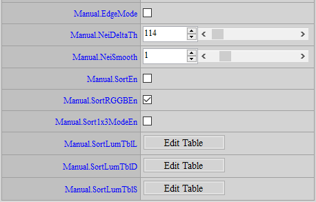
EdgeMode: Edge mode enable. It removes 0 ~ 1 brightest or darkest pixel in the neighboring pixels.
NeiDeltaTh: Threshold value of difference between 8 neighboring pixels and the average value of these 8 pixels. The number (count) of difference larger than this value will be accumulated.
NeiSmooth: Accumulative threshold. If the count is smaller than the threshold, the brightest (or the darkest) pixel will be replaced.
SortEn: Sort mode enable. Sort the neighboring pixels in order to screen out the brightest (darkest) pixel that meets the following conditions — the difference between the brightest (darkest) pixel and the second brightest (darkest) pixel is large enough, and the difference between the second brightest (darkest) pixel and the third brightest (darkest) pixel is small enough. It means that only one pixel around is very bright (dark), and the other pixels are of similar brightness (darkness), and so we can replace that one bright (dark) pixel. The maximum number of compensations is removing 0 ~ 2 brightest pixel and 0 ~ 1 darkest pixel.
SortRGGBEn: Enables the sort mode of each channel.
Sort1x3ModeEn: Enables 1x3 mode. If the two pixels around the center pixel happen to be the brightest and the second brightest pixels, and the difference between the second brightest pixel and the third brightest pixel is greater than SortLumaTblL, the two brightest pixels will be replaced by the third brightest pixel.
SortLumaTblL: Threshold values of the two brightest pixels, which can be tuned by luminance. Value greater than this threshold will trigger replacement. Setting larger threshold value will require the brightest pixel to be much brighter than the second brightest pixel to be replaced by the second brightest pixel, suggesting stricter judgement condition.
SortLumaTblD: Threshold values of the two darkest pixels, which can be tuned by luminance. Value greater than this threshold will trigger replacement. Setting larger threshold value will require the darkest pixel to be much darker than the second darkest pixel to be replaced by the second darkest pixel, suggesting stricter judgement condition.
SortLumaTblS: Threshold values of the second and third brightest (darkest) pixels, which can be tuned by luminance. Value smaller than this threshold will trigger replacement. Setting smaller threshold value will require the second and third brightest (darkest) pixels to be more similar to replace the brightest (darkest) pixel, suggesting stricter judgement condition.
Adjustment Flow
-
If there are defective pixels unable to be compensated by DynamicDP, try to enable EdgeMode or SortEn. The stronger the strength, the more defects would be compensated. However, more details will be damaged.
-
DynamicDP_Cluster setting is suggested to be eased so as to detect the majority of defective pixels, and perform blending by the defect level
NRDeSpike
NRDeSpike handles peak noise by drawing the pixel of concern close to the median of the neighboring pixel. This function, therefore, is only capable of weakening the peak noise rather than eliminating it completely. (Return to IQ Tuning Flow Chart)
If you want to turn off this IP, go to the Enable Control page and click Disable.
Adjustment Interface
Select “BayerDenoise” from the menu on the left-hand side, and NRDeSpike Interface will pop up on the main screen to the right.
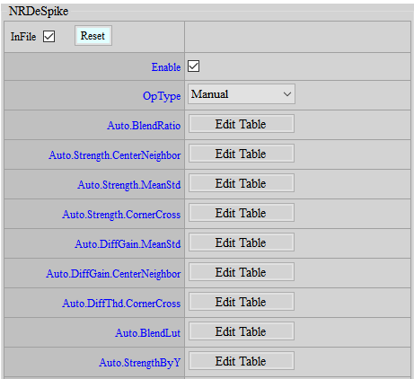
Parameter Description
NRDeSpike employs the following three methods simultaneously to determine the strength of depeak. The weakest one will be taken as the final strength.
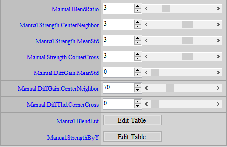
< CenterNeighbor >
Strength: The strength of CenterNeighbor method. Parameter range: 0 ~ 5. The greater the value, the stronger the strength.
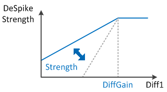
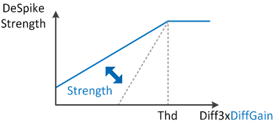
DiffGain: The threshold of CenterNeighbor method. Value larger than this threshold will set depeak strength to the maximum. Parameter range: 0 ~ 255. The smaller the value, the more likely the strongest depeak strength will be applied.
< CornerCross >
Strength: The strength of CornerCross method. Parameter range: 0 ~ 5. The greater the value, the stronger the strength.
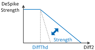
DiffThd: The threshold of CornerCross method. Value smaller than this threshold will set depeak strength to the maximum. Parameter range: 0 ~ 255. The greater the value, the more likely the strongest depeak strength will be applied.
< MeanStd >
Strength: The strength of MeanStd method. Parameter range: 0 ~ 5. The greater the value, the stronger the strength.
DiffGain: The gain value in the determining conditions of MeanStd method. Parameter range: 0 ~ 31. The greater the value, the easier the strongest depeak strength will be applied to the pixel.
BlendRatio: Global strength setting, parameter range: 0 ~ 15. The greater the value, the less obvious the peak.
BlendLut: Select median/mean blending ratio. Parameter range: 0 ~ 2047. The horizontal axis represents the extent of difference between the center pixels and the neighboring pixels. The closer to the right end, the greater the difference. The greater the value, the closer the blending ratio leans toward the median setting; the smaller the value, the closer to the mean setting.
StrengthByY: Apply strength based on different brightness. Parameter range: 0 ~ 64. 64 means no adjustment. The smaller the value, the weaker the strength.
Adjustment Flow
Since the weakest strength of the three methods will be selected as the final strength, adjusting individual parameter may not lead to expected effects. We suggest following the following steps to achieve the best possible adjustment.
-
Set BlendRatio to 15 for the convenience of observation.
-
Find out the optimal parameters for each method. Set the strength of the other two to the maximum while adjusting one of the three methods.
< Taking CenterNeighbor as an example >
-
Set CornerCross and MeanStd to the maximum.
Strength.CornerCross = 5
DiffThd.CornerCross = 255
Strength.MeanStd = 5
DiffGain.MeanStd = 31
-
Set Strength.CenterNeighbor to 0, and lower DiffGain.CenterNeighbor from 255 gradually until peak noises and details reach an acceptable balance.
-
Write down the adjusted parameters.
-
-
Referring to Step 2 to adjust the parameters of the rest two methods, and then copy the optimal parameter values to the corresponding fields on the tool interface.
-
Lower BlendRatio gradually until peak noises and details reach an acceptable balance.
-
Since Spike and DPC share same source input, defective pixels can be blended into the result of Spike compensation. In this case, you can adjust BlendLut to lead the spike result toward the median method, in a bid to exclude the defective pixel. If no such problem occurs, you can still apply the mean method to obtain a smoother picture.
Adjustment of NR3D, NRLuma and NRChroma
NR3D is a very powerful function. Apart from reducing temporal noise, NR3D also adjusts the strength of NRLuma and Sharpness for static and motion areas. Hence, we suggest that you start with NR3D first. Enable NRChroma if necessary. (Return to IQ Tuning Flow Chart)
NR3D ON
NR3D is primarily used to reduce temporal noise, including Y and color noises. Stronger NR3D can effectively reduce noise, but there’s the side effect of creating ghost images. Therefore, we suggest that you adjust to a point where noise and ghost images reach an acceptable balance.
If you want to turn off this IP, go to the Enable Control page and click Disable.
Adjustment Interface
Select “Denoise” from the menu on the left-hand side, and NR3D Interface will pop up.
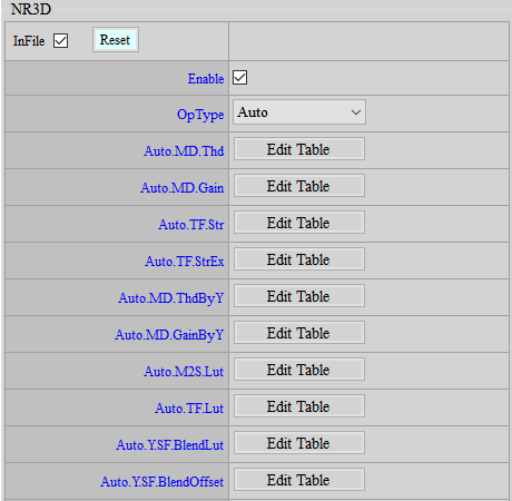
Parameter Description
< Spatial Domain Denoise, SF Parameters >
To control these parameters, please refer to NRLuma, NRLuma_Adv, NRChroma and NRChroma_Adv.
< Temporal Domain Denoise, MD, TF Parameters >
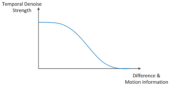
TF.LUT: Mainly use difference and motion information to determine the strength of temporal denoise. If the difference and motion are small, it is likely to be a static area, otherwise it is likely to be a dynamic area. The value range is 0 ~ 4095.
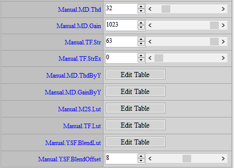
MD.Thd: Motion threshold control. Parameter range: 0 ~ 255. The greater the value, the stronger NR3D. Areas with motion lower than the threshold value will be judged as static areas. It is recommended not to set it to more than 10.
MD.Gain: Motion scale control. Parameter range: 0 ~ 10230. The greater the value, the smaller the motion information, and the stronger NR3D.
MD.ThdByY: Motion threshold value based on brightness. Parameter range: 0 ~ 255. The greater the value, the stronger NR3D.
MD.GainByY: Motion scale based on brightness. Parameter range: 0 ~ 255. The greater the value, the smaller the motion information, and the stronger NR3D. This parameter enhances specific brightness with greater noise or reduces brightness suspected of ghost images.
TF.Str: NR3D strength. The value range is 0 ~ 64. The larger the value, the stronger the NR3D.
TF.StrEx: NR3D extended strength. The value range is 0 ~ 64. The larger the value, the stronger the NR3D.
M2S.LUT : NR3D intensity control for the transition from dynamic area to static area. The value range is 0 ~ 31. The larger the value, the weaker the NR3D and the stronger the NRLuma. It is recommended that the curve change from dynamic to static area should not be too steep, otherwise the transition area between the moving object and the static area will be unnatural.
< Denoise by motion Parameters >
Y.SF.BlendLUT: Adjust the intensity of NRLuma according to the motion information. The value range is 0 ~ 16. From left to right represents motion to stillness, the larger the value, the stronger the NRLuma intensity.
Y.SF.BlendOffset: Determine how much 3dnr intensity to compensate for when writing back the 3DNR reference frame for the motion part. The value range is 0~16. The larger the value, the more 3dnr proportion is compensated.
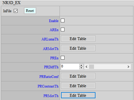
< NR3D Alpha Blending Refine Series Parameters>
AREn: Switch to limit NR3D intensity based on brightness and motion information. The value range is 0 ~ 1.
ARLumaTh: When < Luma < LumaTh[0] >, the NR3D intensity remains unchanged. When < Luma > LumaTh[1] >, the NR3D intensity is 0. The value range is 0 ~ 255.
ARMotTh: When < motion < MotTh[0] >, the NR3D intensity remains unchanged. When < motion > MotTh[1] >, the NR3D intensity is 0. The value range is 0 ~ 255.
< NR3D Purple False Color Compensation Series Parameters>
When the image is rotating, turn on this function to help NR3D determine the motion near the purple edge to avoid misjudging it as dynamic and causing 3dnr disturbance.
First, DiffTh, RatioConf, and ContrastTh are used to determine the degree of purple fringing. If all three conditions are considered purple fringing, the motion near the purple fringing can be reallocated to a more static state.
PREn: Motion switch to assist NR3D in determining purple fringing.
PRDiffTh: According to the result of PFC compensation, if the PFC compensation of this point is greater than PRDiffTh, it is judged as purple fringing. The value range is 0~4095. The smaller the value, the easier it is to judge as purple fringing.
PRRatioConf: Determine whether the color is similar to purple fringing. The value range is 0~16. The horizontal axis is the color correlation. The further to the right, the more similar to purple fringing. The vertical axis is the degree of purple fringing judgment. The larger the value, the easier it is to judge as purple fringing.
PRContrastTh: Determine the contrast level. When the contrast is high, purple fringing is more likely to occur. The value range is 0~16. If the contrast of this area is less than ContrastTh1, no processing is performed. If it is greater than ContrastTh2, it is judged as purple fringing.
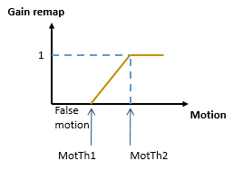
PRMotTh: If the purple fringing level is high, the following settings will be used to re-determine the motion information. If it is not purple fringing, the motion information will remain unchanged. MotTh1 is set, and motion below this level is considered misjudged information, so the motion will be reallocated to 0, representing stillness, and greater than MotTh2, representing normal motion, and remain unchanged.
Adjustment Flow
-
Adjust the strength of NR3D with respect to still images first to lower the level of dynamic noise in the picture.
- Making adjustment to the strength of NR3D aims to stabilize the picture in general. We suggest that you set TF.Str to 63 and increase MD.Gain to the extent that picture becomes stabilized. If a very high setting of MD.Gain is required to stabilize the picture, you may increase MD.Thd from time to time, but the value should preferably be no greater than 10.
-
Make adjustments based on the change of strength of NR3D in the area after motion ends.
-
Adjust M2S.LUT. The curve of M2S.LUT should not be too steep; otherwise, the borderline of transition from blurry to clear in post-motion area will become visible and unnatural.
-
You can make fine adjustments based on the recommended values. If you don't want to see afterimages, you need to set a larger value. At this time, the NRLuma of the area after the object moves will be stronger and last longer, and the NR3D will be weaker, which looks more disturbed; On the contrary, if you want the area to be clearer after the object moves and can accept some residual images, set the value to a smaller value. The disturbance will be smaller but there may be particle noise.
-
Suggested values: {24, 18, 11, 8, 7, 7, 6, 6, 6, 5, 5, 5, 5, 4, 4, 4}
-
-
Fine-tune the balance between motion blur and noise.
-
Adjust Y.SF.BlendLUT, from left to right represents the dynamic area to the static area. Slowly increase the value until the motion blur and noise are acceptable. The last value is recommended to be fixed at 0 to maintain the details of the static picture. It is recommended to adjust BlendRatio and FilterLevel of NRLuma at the same time.
-
For the noise after movement, in addition to adjusting the NR2D intensity according to the motion, you can also adjust the Y.SF.BlendOffset to compensate a little NR3D according to the motion to reduce the noise. And because it will only update the NR3D reference frame, it will not affect the image screen.
-
-
For brightness with severe ghosting, you can use MD.GainByY to make fine adjustments. Slowly reduce the value of the corresponding brightness area to a level where both ghosting and noise are acceptable.
-
When the gain is getting higher and higher, it is not enough to rely on NRLuma alone for motion noise. At this time, you can modify TF.LUT to make the curve drop more slowly to increase the strength of NR3D in the moving area, but you must also consider the severity of the smear. The last value does not have to be set to 0, but if it causes pink smear on the edge of the moving object, you can use the AREn function to limit the intensity of the brighter and more dynamic NR3D to avoid this smear.
-
NR3D has an additional mechanism that can make the result after NR3D close to the result of the current frame, but it will also make the result of NR3D disturbed. If additional adjustment is needed, you can use Dummy_Ex/Dummy1 to control it. Please refer to the Dummy_Ex section for detailed introduction.
-
There are two modes for NR3D to pass motion information to the next stage. If additional adjustment is required, you can use Dummy_Ex/Dummy3 to control it. Please refer to the Dummy_Ex section for detailed introduction.
NR3D OFF
Certain ICs do not feature DRAM for cost-saving reason, and NR3D will be unavailable. Several recommended denoise adjustments in the absence of NR3D are set out below.
Adjustment Interface
Please refer to NR3D ON Adjustment Interface.
Parameter Description
Please refer to NR3D ON Parameter Description.
Adjustment Flow
-
Make sure that Iqfile is using the 3dnr off version.
-
In the 3DNR interface, only spatial domain series parameters, including Y.SF.STR, can be adjusted.
-
In the NRLuma interface, it is recommended to set Wei to 63 (maximum value) and adjust LumaX and LumaStrengthByY.
-
The Despike adjustment method is the same as 3DNR on.
-
If there is still demand, you can adjust the remaining denoises. The adjustment method is the same as 3DNR on.
NRLuma
Adjustment Interface
Select “Denoise” from the menu on the left-hand side, and NRLuma Interface will pop up on the main screen to the right.
If you want to turn off this IP, go to the Enable Control page and click Disable.
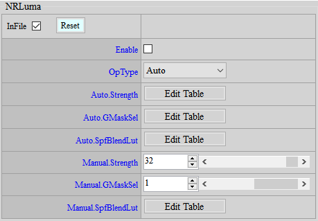
Parameter Description
Strength: NRLuma final strength control. The value range is 0~63, the larger the value, the stronger it is.
GMaskSel: Select Gaussian Filter size. The value range is 0~1, 0 represents a smaller range, and 1 represents a larger range.
SpfBlendLut: Use Gaussian Filter (SPF) & Biliteral Filter for blending. If the center point is similar to the surrounding area, more Gaussian results can be selected to achieve a smoother effect. If the difference is large, use Biliteral results to retain the details. The horizontal axis represents the degree of similarity, the more to the right, the more similar. The vertical axis represents the Gaussian blending strength, the value range is 0 ~ 256, the larger the value, the more blending. To adjust the Bilteral filter strength, you can use Dummy/Dummy1 to control it. Please refer to the Dummy section for detailed introduction.
Adjustment Flow
Basically, when adjusting NR3D, the spatial denoise intensity should have been adjusted to an appropriate level. If necessary, you can use NRLuma to make further adjustments.
- Adjust SpfBlendLut to balance noise suppression and detail preservation.
NRLuma_Adv
Adjustment Interface
Select “Denoise” from the menu on the left-hand side, and NRLuma_Adv Interface will pop up on the main screen to the right.
If you want to turn off this IP, go to the Enable Control page and click Disable.
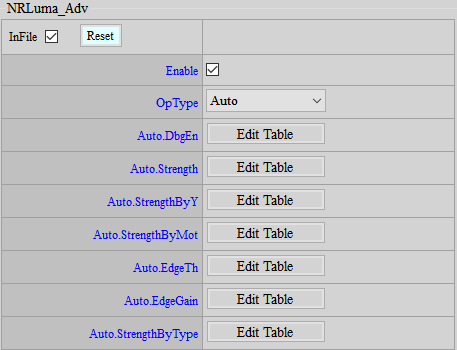
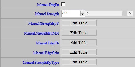
Parameter Description
DbgEn: Display the Edge strength detected by NRLuma_Adv.
Strength: The final strength control of NRLuma_Adv. The value range is 0~255, the larger the value, the stronger it is.
StrengthByY: For different brightness, different NR strengths are controlled. The rightward of the horizontal axis represents a higher brightness. The value range is 0~32, and the larger the value, the stronger it is. However, the initial value is 0, which means that the strength of the brightness is not adjusted, so the strength can only be strengthened here.
StrengthByMot: For different motions, different NR strengths are given. The rightward of the horizontal axis means the smaller the motion. The value range is 0~32, the larger the value, the stronger it is. However, the initial value is 0, which means that the intensity of the brightness is not adjusted, so the intensity can only be strengthened here.
EdgeTh: Control the judgment of Edge. The more to the right of the horizontal axis, the greater the brightness. When Edge is less than Th, it is considered as noise and NR processing is performed. When it exceeds Th, it is judged as Edge. The stronger the Edge, the weaker the NR. The value range is 0~16383. The larger the value, the less likely it is to be judged as Edge.
EdgeGain: Control the judgment of Edge. The more to the right of the horizontal axis, the greater the brightness. For Edge greater than Th, control the Edge strength. The stronger the Edge, the weaker the NR. The value range is 0~65535. The larger the value, the stronger the Edge strength.
StrengthByType: There are two types of filters in NR. StrengthByType[0] is the filter strength that preserves details, and StrengthByType[1] is the filter strength that has a better de-noising effect but will damage details. The two filter results are blended based on the edge strength. The larger the value, the stronger the NR effect.
Adjustment Flow
It is mainly based on the results of NR3D and NRLuma, and then fine-tuned for use.
-
Adjust EdgeTh and EdgeGain to determine which areas are Edge.
-
Set StrengthByY and ByMot to 0 first, adjust the StrengthByType parameter, control the Edge area and non-Edge area, and give different degrees of NR strength.
-
Enhance NR according to different brightness and motion levels.
NRChroma
NRChroma aims to suppress the color noise on screen.
If you want to turn off this IP, go to the Enable Control page and click Disable.
Adjustment Interface
Select “Denois” from the menu on the left-hand side, and NRChroma Interface will pop up on the main screen to the right.
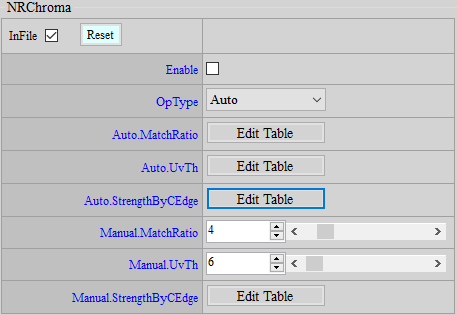
Parameter Description
MatchRatio: Match ratio threshold, the larger the value, the stronger it is. The value range is 0 ~ 31.
UvTh: U/V noise threshold, the larger the value, the stronger it is. The value range is 0 ~ 256.
StrengthByCEdge: Control the NRChroma strength according to the color edge, the larger the value, the stronger it is. The value range is 0 ~ 511.
Adjustment Flow
-
Adjust MatchRatio and UvTh. You can see that color noise will spread out. If it is too strong, there will be color overflow. Adjust it to an acceptable range.
-
Reduce StrengthByCEdge to further suppress the part with color overflow.
NRChroma_Adv
NRChroma_Adv aims to suppress the color noise on screen.
If you want to turn off this IP, go to the Enable Control page and click Disable.
Adjustment Interface
Select “Denoise” from the menu on the left-hand side, and NRChroma_Adv Interface will pop up on the main screen to the right.
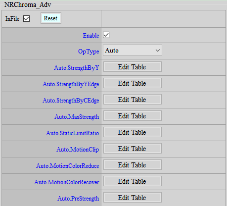
Parameter Description
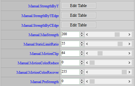
StrengthByY: Assign different levels of NR strength to different brightnesses. The closer to the right end of the horizontal axis, the stronger the brightness. The greater the value, the stronger the strength. Parameter range: 0 ~ 255.
StrengthByYEdge: Use Luma to detect the degree of edge and adjust the level of NR strength according to different edges. The closer to the right end of the horizontal axis, the bigger the edge. The greater the value, the stronger the strength. Parameter range: 0 ~ 63.
StrengthByCEdge: Use Chroma to detect the degree of edge and adjust the level of NR strength according to different edges. The closer to the right end of the horizontal axis, the bigger the edge. The greater the value, the stronger the strength. Parameter range: 0 ~ 255.
MaxStrength: Control the level of NR strength in areas of small Y/C difference. The greater the value, the stronger the strength. Parameter range: 0 ~ 255.
StaticLimitRatio: Control NR strength of the static areas. The greater the value, the stronger the strength. Parameter range: 0 ~ 63.
MotionClip: Assign greater level of NR strength to motion areas. The greater the value, the stronger the strength. Parameter range: 0 ~ 255.
MotionColorReduce: Reduce the saturation of motion areas. The greater the value, the greater level of saturation is reduced. Parameter range: 0 ~ 255.
MotionColorRecover: Recover the gain of saturation reduced by MotionColorReduce against motion areas. The greater the value, the greater level of saturation is recovered. Parameter range: 0 ~ 255.
PreStrength: Perform simple Chroma noise reduction. The greater the value, the stronger the strength. Parameter range: 0 ~ 128.
Adjustment Flow
- Set MotionClip to 0 first.
- Observe static area and make corresponding adjustments to MaxStrength and StaticLimitRatio until NR achieves an acceptable range of color noise.
- Observe motion area and make corresponding adjustment to MotionClip to enhance the NR strength on motion area based on the strength level set in Step 1. If the level of adjustment to MotionClip is not strong enough, return to Step 1 for further enhancement of strength.
- If necessary, you may adjust MotionColorReduce to suppress the level of saturation against motion areas. Such adjustment allows NRChroma_Adv to remove color noise more easily. If a decrease of saturation in motion area is undesired, adjust MotionColorRecover to regain the saturation in motion area.
Sharpness Adjustment
The sharpening intensity can be controlled according to different conditions, such as the sharpening intensity of different brightness, the sharpening intensity of the distance from the center of the picture, the sharpening intensity of the black and white edges, etc.
If you want to turn off this IP, go to the Enable Control page and click Disable.
Sharpness
Adjustment Interface
Select Sharpness in the menu on the left, and then find the Sharpness interface on the main screen on the right.
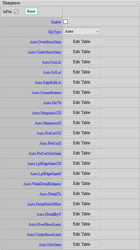
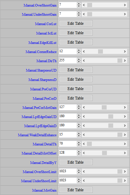
Parameter Description
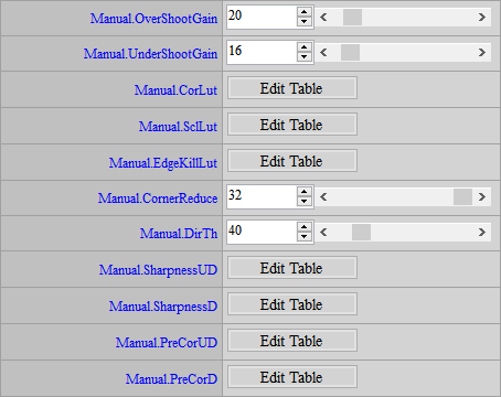
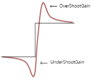
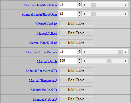
OverShootGain: Adjust the intensity of the white edge, the value range is 0~255, the larger the value, the stronger the intensity.
UnderShootGain: Adjust the intensity of the black edge, the value range is 0~255, the larger the intensity is.
If the above two are enhanced too much, it may cause noise amplification. In this case, CorLut can be used to suppress the impact of OverShootGain and UnderShootGain on noise, but details will be lost.
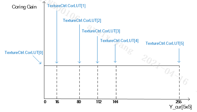
CorLut: Adjust the Edge output according to the brightness. The value range is 0~255. The larger the value, the weaker the Edge.
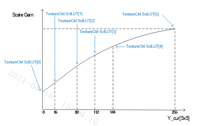
SclLut: Adjust the Edge output according to the brightness. The value range is 0~255. The larger the value, the stronger the Edge.
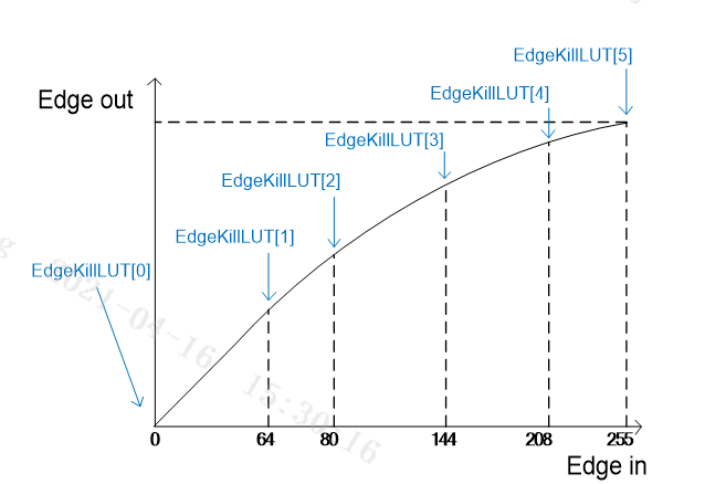
EdgeKillLut: It is divided into 0~255 equal parts according to the Edge strength. There are six nodes in total to adjust the Edge output size. The first grid is recommended to be 0 to prevent the noise points from being enhanced by the Edge. The value range is 0~1023. The larger the value, the stronger the Edge.
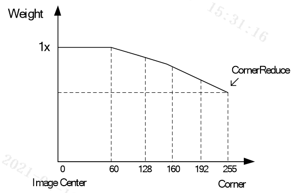
CornerReduce: The farther away from the center of the picture, the lower the sharpening effect. The closer the lens is to the periphery, the worse the image value. Reducing the sharpening effect can improve edge noise. Set the sharpness strength of the corner. The value range is 0~32. The center strength will not change, and the corresponding strength will be interpolated from the center to the corner.
DirTh: The threshold for directional judgment. When the value is greater than this threshold, a directional filter is used to enhance the edge. The advantage is that the edge is more continuous, but the disadvantage is that the edge of small details is enhanced, making the image unnatural.
SharpnessUD: Can enhance non-directional detail textures, and can be used to improve the clarity of fine textures such as hair and grass. SharpnessUD[0] can be used to process high frequencies, and SharpnessUD[1] can be used to process low frequencies. The value range is 0~1023. The larger the value, the stronger the Edge.
SharpnessD: Can enhance the sharpness according to the edge direction, and enhance the image edge as a whole. However, too strong a value will cause jaggedness. SharpnessD[0] can be used to process high frequencies, and SharpnessD[1] can be used to process low frequencies. The value range is 0~1023. The larger the value, the stronger the edge.
PreCorUD: Coring is performed for non-directionality. PreCorUD[0] is for high frequencies, and PreCorUD[1] is for low frequencies. The value range is 0~63. The larger the value, the weaker the Edge.
PreCorD: Coring for directionality. PreCorD[0] is for high frequencies, and PreCorD[1] is for low frequencies. The value range is 0~63. The larger the value, the weaker the Edge.
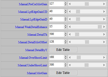
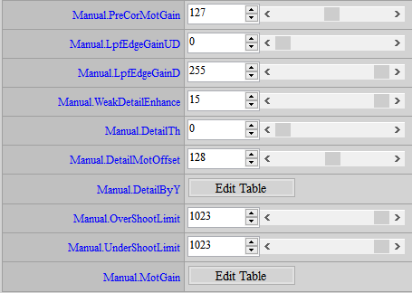
PreCorMotGain: For mobile areas, based on the setting value of PreCorUD and PreCorD, it is used to strengthen the coring. The value range is 0~255. The larger the value, the weaker the edge of the moving area.
LpfEdgeGainUD: Select the non-directional high-frequency and low-frequency output ratio control, and use the results of SharpnessUD, PreCorUD, and PreCorMotGain to control EdgeGain. The value range is 0~255. The larger the value, the stronger the low frequency and the weaker the high frequency. The smaller the value, the weaker the low frequency and the stronger the high frequency.
LpfEdgeGainD: Select the directional high-frequency and low-frequency output ratio control, and use the results of SharpnessD, PreCorD, and PreCorMotGain to control EdgeGain. The value range is 0~255. The larger the value, the stronger the low frequency and the weaker the high frequency. The smaller the value, the weaker the low frequency and the stronger the high frequency.
WeakDetailEnhance: Enhance the edge of weak textures. The value range is 0~255. The larger the value, the stronger the edge.
DetailTh: SharpnessUD threshold, which can be used to reduce the edge of flat areas.
DetailMotOffset: Adjust SharpnessUD according to the degree of movement.
DetailByY: Adjust SharpnessUD according to brightness.
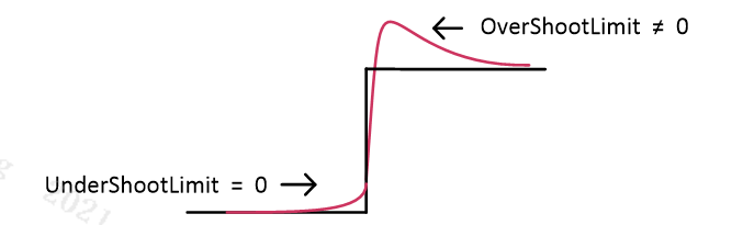
OverShootLimit: Refer to the brightest point around for adjustment. If set to 0, the upper limit of the edge is the Y value of the brightest point around, which means there will be no overshoot.
UnderShootLimit: Refer to the darkest point around for adjustment. If it is set to 0, the lower limit of the edge is the Y value of the darkest point around, which means there will be no undershoot.
MotionGain: Adjust the final Edge according to the degree of movement. The horizontal axis represents the degree of movement, and the more to the right, the more still. The value range is 0~255. The larger the value, the stronger the Edge. The value of 128 means no adjustment.
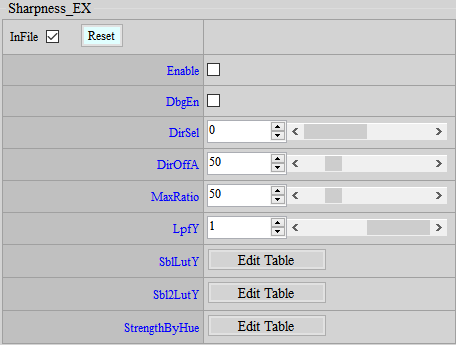
< Sharpness_EX >
If you want to turn off this IP, go to the Enable Control page and click Disable.
DbgEn: debug mode, only the edge to be compensated is displayed on the screen.
DirSel: Directionality judgment of SharpnessD. A value of 0 represents the maximum value of each direction to represent the direction. A value of 1 represents the direction judged by a simple anti-noise method.
DirOffA: SharpnessD and SharpnessUD will determine the blending ratio on both sides according to the strength of the direction, and the DirOffA parameter can enhance the output of SharpnessUD. The value range is 0~255, and the higher the value, the stronger the non-directional edge.
MaxRatio: If the line segment is discontinuous, you can adjust DirTh first. If it does not help much, then increase this parameter appropriately. The value range is 0~255. The higher the value, the stronger the edge.
LpfY: For the horizontal axis brightness of CorLut and SclLut, LPF processing is performed to avoid using different Cor and Scl results due to brightness fluctuations. 0 means diabling LPF, 1 means enabling LPF.
SblLutY: The low-frequency part of SharpnessD will first be filtered by Sobel to determine the intensity. This parameter can adjust different intensities according to different brightness. The horizontal axis represents brightness, and the right side represents brighter. The value range is 0~255. The higher the value, the stronger the intensity.
Sbl2LutY: The high frequency part of SharpnessD will first be filtered by Sobel to determine the intensity. This parameter can adjust different intensities according to different brightness. The horizontal axis represents brightness, and the right side represents brighter. The value range is 0~255. The higher the value, the stronger the intensity.
StrengthByHue: Adjust Sharpness according to Hue. You can strengthen or weaken the edge for a specific color. The horizontal axis is Hue, which is divided into 24 equal parts from 0 degrees to 360 degrees. The larger the value, the stronger the edge. 64 means no adjustment.
Adjustment Flow
If you follow the previous suggestions, the initial Sharpness parameters should be maintained as follows:
-
First observe the area with strong edge, and adjust OverShootGain and UnderShootGain until the enhancement of black and white edges is acceptable.
-
Adjust DirTh to avoid continuous line segments that reach the edge in the UD direction, which would cause discontinuous line segments.
-
Observe whether there is noise in the flat area that is enhanced by sharpness. If so, you can try to increase the PreCorUD and PreCorD of high and low frequencies to exclude those places, but be aware that the larger the setting, the more places that cannot be added. Edges can also easily cause the picture to look blurry, so when adjusting, you should also pay attention to whether there are areas where edges should be added that have been excluded. If the noise changes are difficult to observe, you can first enlarge OverShootGain and UnderShootGain to an exaggerated level to facilitate coring adjustment. However, there is no need to remove 100% of the noise during adjustment, because OverShootGain and UnderShootGain will be set back to normal values later. Sometimes some small noise may not be visible. Lowering the node in front of the Edge Lut can also have a similar effect, but it is relatively difficult to adjust. Unless you are very familiar with the Edge Lut, it is not recommended to adjust it here.
-
Observe whether there is noise in the dark area that is enhanced by sharpness. If so, you can slowly increase SclLut to reduce the sharpness in the dark area and inhibit the generation of noise.
-
Check if the noise in the corners of the image is too loud due to ALSC correction. If so, lower CornerReduce to reduce the sharpness of the corners.
-
Adjust SharpnessUD and SharpnessD to control non-directional and directional details, and increase DetailTh to reduce the strong SharpnessUD on flat areas. If necessary, adjust DetailByY.
-
If you need to limit the overshoot or undershoot edge, you can adjust OverShootLimit and UnderShootLimit.
WDR
Wide Dynamic Range (WDR) is used to increase the dynamic range, allowing details of both bright and dark areas to be resolved in the same image.
WDR
Belongs to local WDR, which enhances the image dynamic range regionally. It is recommended to use this option when adjusting WDR.
If you want to turn off this IP, go to the Enable Control page and click Disable.
Adjustment Interface
Select WDR in the left menu and the WDR interface will appear.

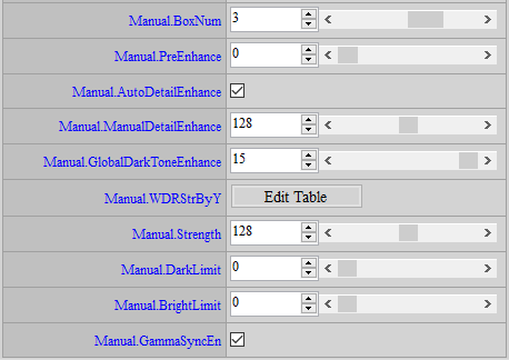
Parameter Description
BoxNum: Provides 2 to 4 sizes based on the aspect ratio of the sensor. It can be adjusted based on the size of the object to be focused on in the scene. The more Box Num, the smaller the Box. It is more suitable when the object to be focused on in the picture is smaller. It cannot be changed by iso.
PreEnhance: The ratio of the dynamic range of the bright area. The larger the value, the larger the dynamic range allocated to the bright area. The smaller the value, the larger the dynamic range allocated to the dark area. The value range is 1 ~ 6, and 2 is the default value. In addition, 11 ~ 15 are added, and they are adjusted according to 2. The larger the value, the brighter the dark area, but the more blurred the overall image. Other values are invalid. It is not recommended to switch different curves by iso, as it will cause flickering problems. If GammaSyncEn is turned on, PreEnhance will be invalid.
AutoDetailEnhance: Additional detail enhancement for brightening and darkening areas, 1: automatic control, 0: manual control.
ManualDetailEnhance: If AutoDetailEnhance is set to 0, you can manually control the degree of detail enhancement in bright and dark areas. The value range is 0 ~ 255. The larger the value, the stronger the detail enhancement.
DarkToneEnhance: Controls global tone mapping, providing the following 16 curves to choose from. The larger the number, the brighter the dark areas will be. (The 16 groups in HDR mode are different from the 16 groups in Linear mode. In HDR, 0~6 is a brightening mode, and 7~15 and above are the second brightening mode.) It is not recommended to change the setting by changing iso, because flickering may occur when switching curves. The alternative is to use a fixed GlobalDarkToneEnhance curve but modify WDRStrByY and Strength by iso to achieve the desired effect.
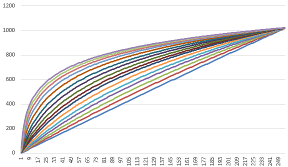
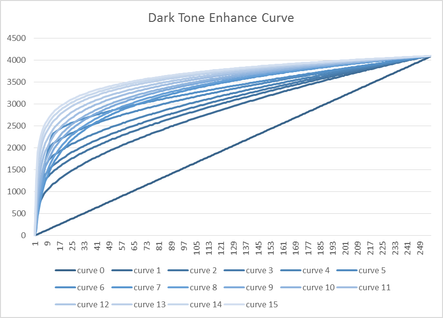
WDRStrByY: Controls WDR intensity based on brightness. The value range is 0 ~ 255, the larger the value, the stronger the WDR.
Strength: Overall strength of WDR. The value range is 0 ~ 255, the larger the value, the stronger the WDR.
Dark Limit / Bright Limit: Limit the intensity of WDR. The value range is 0~255, and the brightness and darkness are controlled separately. If you don’t want the dark areas to be brightened too much, you can set a larger DarkLimit value. If you don’t want the bright areas to be too dark, you can set a larger BrightLimit.
GammaSyncEn: WDR and Gamma linkage switch. If disabled, it will be fixed to use the 0th group of Gamma Lut. Dynamic linkage of Gamma/WDR can obtain better WDR effect, but if Gamma is switched by iso, flickering may occur when Gamma changes. In this case, it is recommended to set this item to disable.
Adjustment Flow
-
It is recommended to enable WDR directly first and observe whether the preset effect is sufficient.
-
If the strength is too strong or too weak, you can simply adjust the Strength.
-
If you are more concerned about the brightening effect in dark areas, you can adjust DarkToneEnhance.
-
For the rest, further adjust WDRStrByY or Dark Limit / Bright Limit according to the intensity of each brightness.
WDRCurve
It is used to replace the Dark Tone Enhance Curve in WDR and provide the function of modifying the curve by yourself. If the WDR Curve API is enabled, the 16 Curves in Dark Tone Enhance of the original WDR API are disabled and controlled by WDRCurveAdv. It is not recommended to change the settings by changing iso, because flickering may occur when the Curve is switched. An alternative is to use a fixed GlobalDarkToneEnhance curve but modify WDRStrByY and Strength by iso to achieve the desired effect.
Adjustment Interface
Select WDR in the left menu and the WDRCurveAdv interface will appear.
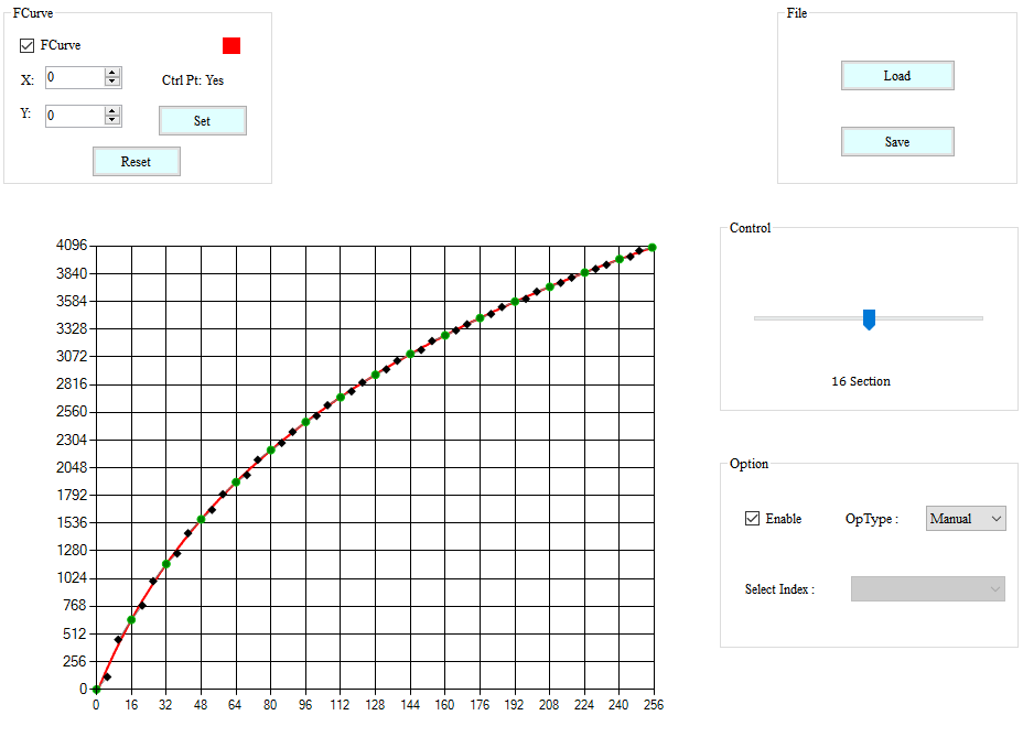
Parameter Description
From the Control project, adjust the number of nodes to generate the curve.
Adjustment Flow
Adjust the curve to achieve the appropriate distribution of light and dark areas.
Defog
Defog function aims to achieve better and starker contrast.
If you want to turn off this IP, go to the Enable Control page and click Disable.
Adjustment Interface
Select “WDR” from the menu on the left-hand side, and Defog Interface will pop up.
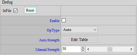
Parameter Description
Strength: Set the variable strength value of contrast, brightness, and grayscale. The default value is 50.
Adjustment Flow
Adjust Strength to achieve a better contrast of image.
DUMMY
Dummy API is a default interface, through which new functions will be added, as a way to prevent interfaces from being increased each time when a new function is added and to avoid the original interface structure being affected. All default values are “-1”, meaning that this function is bypassed. If Dummy API is enabled to save bin files, make sure you check the “InFile” box so that parameters can be properly saved.
Dummy
The interface supports adjustment by ISO.
Adjustment Interface
Select “Dummy” from the menu on the left-hand side, and Dummy Interface will pop up on the main screen to the right.
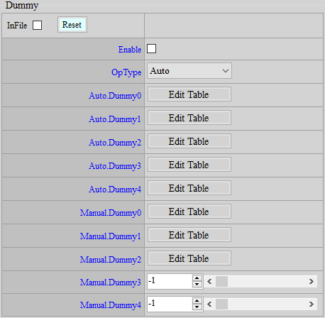
Parameter Description
Dummy0: Currently not functional. Default value is -1. Parameter range: -1 ~ 255.
Dummy1: NRLuma bilateral filter intensity. Dummy1[0] is the intensity, and the value range is 0 ~ 7. Dummy1[1~32] is the weight table. The horizontal axis is the difference from the center point. The smaller the difference, the greater the weight. The value range is 0 ~ 31.
Dummy2: Adjust SharpnessUD according to the degree of movement. It has the same function as Sharpness DetailMotOffset, but Sharpness DetailMotOffset has only one value that can be adjusted, and the others are automatically interpolated, while Dummy2 can be adjusted according to different degrees of movement. If Dummy2 is enabled, Sharpness DetailMotOffset will automatically become invalid, and only Dummy2[0~15] will be effective. The value range is: 0 ~ 255.
Dummy3: Currently not functional. Default value is “-1”. Parameter range: -1 ~ 255.
Dummy4: Currently not functional. Default value is “-1”. Parameter range: -1 ~ 255.
Dummy_EX
The Dummy_EX interface does support adjustment by ISO.
Adjustment Interface
Select “Dummy” from the menu on the left-hand side, and Dummy_EX Interface will pop up on the main screen to the right.
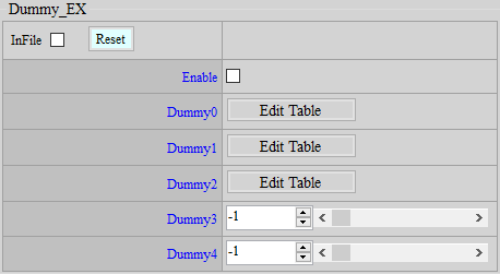
Parameter Description
Dummy0: EdgeKillLut horizontal axis node in Shaprness, added with powers of 2. Only Dummy0[0~5] is effective. The value range is: 0 ~ 15.
Dummy1: Make the result after 3DNR close to the result of the current frame. Dummy1[0] is the switch, and the value range is: 0 ~ 1. Dummy1[1] is the maximum value of movement. The smaller the value, the more the 3DNR result is restricted to be close to the result of the current frame. The value range is: 0 ~ 255. Dummy1[2] is the movement threshold. If the difference between the 3DNR result and the current frame is smaller than this value, this function will have no effect. The value range is: 0 ~ 255.
Dummy2: Currently not functional. Default value is “-1”. Parameter range: -1 ~ 255.
Dummy3: The way 3DNR transmits motion information to the next stage. 0 means directly based on the difference between the current frame and the reference frame. 1 means an additional restriction. In the case of moving to still, the motion information of each frame changes by at most 1, that is, the motion will change more slowly. The value range is: 0 ~ 1.
Dummy4: Currently not functional. Default value is “-1”. Parameter range: -1 ~ 255.
TEMPERATURE SETTING
When chip temperature changes, corresponding adjustment can be made to IQ to achieve better visual effects.
Temperature
Set up temperature nodes and corresponding IQ settings.
Adjustment Interface
Select “Temperature” from the menu on the left-hand side, and Temperature Interface will pop up on the main screen to the right.
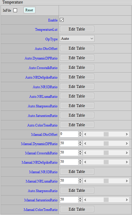
Parameter Description
TemperatureLut: Temperature nodes. Up to 16 nodes are supported.
ObcOffset: Optical black compensation (OBC) offset. The greater the value, the greater the OBC effect. Default value is 0.
DynamicDPRatio: Ratio of the change of DynamicDP strength. The greater the value, the stronger the DynamicDP. Default value is 50.
CrosstalkRatio: Ratio of the change of Crosstalk strength. The greater the value, the stronger the Crosstalk. Default value is 50.
NRDeSpikeRatio: Ratio of the change of NRDeSpike strength. The greater the value, the stronger the NRDeSpike. Default value is 50.
NR3DRatio: Ratio of the change of NR3D strength. The greater the value, the stronger the NR3D. Default value is 50.
NRLumaRatio: Ratio of the change of NRLuma strength. The greater the value, the stronger the NRLuma. Default value is 50.
SharpnessRatio: Ratio of the change of Sharpness, by which OverShootGain and UnderShootGain will be multiplied following this sequence. The greater the value, the sharper the image. Default value is 50.
SaturationRatio: Ratio of the change of Saturation. The greater the value, the more saturated the image. Default value is 50.
ColorToneRatio: Ratio of the change of ColorTone strength, which corresponds to R/G/B following this sequence. The greater the value, the more saturated the image. Default value is 50.
Temperature Info
Obtain current chip temperature.
Adjustment Interface
Select “Temperature” from the menu on the left-hand side, and TemperatureInfo Interface will pop up on the main screen to the right.

Parameter Description
Temperature: Obtain current chip temperature, read only.
DAY NIGHT MODE DETECTION
Detection of the environmental brightness usually relies on the application of ALS (Ambient Light Sensor), which provides information as reference for the determination of Day mode or Night mode. This “Day/Night Detection” function aims to facilitate the Day/Night mode selection without using the ALS. By setting customized determining conditions, you can switch between Day mode and Night mode according to the information provided by this API.
DayNightDetection
The Day/Night Detection API allows user to set respective conditions for the determination of switching from Day mode to Night mode or vice versa, and the detection result will be shown in the DayNightInfo API, which is set out in the next section.
Adjustment Interface
Select “Day/Night Mode” from the menu on the left-hand side to find the DayNightDetection interface.
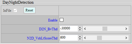
Parameter Description
Enable: Switch of the detection function. Information in DayNightInfo Interface is effective only when Enable is checked.
D2N_BvThd: The threshold value of brightness for determining whether Day mode should be switched to Night mode. If the current brightness value (accessible as “BV” in AEInfo) falls below this threshold, D2N in DayNightInfo Interface will show TRUE. Value range: -1048576 ~ 1048576.
N2D_VsbLtScoreThd: The threshold of “Score” for determining whether Night mode should be switched to Day mode. The Score is calculated by the ratio of visible light to IR light, and a larger value suggests the dominance of visible light in this environment. If the current score (accessible as “N2D_VsbLtScore” in DayNightInfo Interface) is larger than this threshold, D2N in DayNightInfo Interface will show TRUE. Value range: 0 ~ 2000.
DayNightInfo
This API shows detection result. Please note that this API shows the result only and you should still take actions accordingly, such as loading Day/Night API bin file or controlling IR LED, when necessary.
Adjustment Interface
Select Day/Night Mode from the menu on the left-hand side to find DayNightInfo Interface.
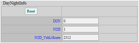
Parameter Description
D2N: Flag that determines whether Day mode should be switched to Night mode. Value “1” means that the current environmental brightness has met the condition of switching to Night mode. Note: The flag is only meaningful when the current mode is Day mode.
N2D: Flag that determines whether Night mode should be switched to Day mode. Value “1” means that the current environmental brightness has met the condition of switching to Day mode. Note: The flag is only meaningful when the current mode is Night mode.
N2D_VsbLtScore: The score is calculated by the ratio of visible light to IR light, and higher score means visible light is more dominant in the environment. In cases where switching to Day mode is considered desirable, users can read this score to set “N2D_VsbLtScoreThd” in DayNightDetection Interface.
NIGHT MODE SETTING
When ambient brightness is low to a certain level, IR light will usually be turned on, and the IR-Cut filter in the lens will be enabled to increase the amount of incoming light. This is in fact a special case, for which certain AE, AWB and IQ settings should be modified accordingly. Due to the use of IR light, Night mode can even apply a very low gain. As such, it is not advised to have Day mode and Night mode share the same bin file and differentiate the two simply by ISO index value. Instead, we suggest that two separate bin files be maintained for Day mode and Night mode, respectively. When mode change is determined necessary by the system, you can then load the corresponding bin file. In the following section, we will provide a detailed description of the settings suggested for noise level reduction in Night mode.
ColorToGray
Enabling IR-Cut filter will cause color to get abnormal, so it is a usual practice to turn the screen from color to gray scale.
Adjustment Interface
Select “ColorToGray” from the menu on the left-hand side, and ColorToGray Interface will pop up on the main screen to the right.
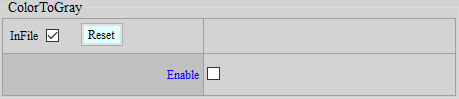
Parameter Description
Enable: Switch to enable the function of color to gray scale conversion.
RGBIR SENSOR TUNING
RGBIR sensor is a special type of sensor which, as compared to normal RGB Bayer sensor, features additional IR pixel for sensing infrared light. In terms of its structure, RGBIR sensor does not feature IR Cut but uses Dual Band filter instead for IR removal, which is done by software at the backend. Our goal in this chapter, therefore, is to provide tips on how to set the IR removal ratio so that the image will share the same color as achieved by common sensors with IR Cut.
RGBIR Ratio Adjustment
Adjustment Interface
Select “RGBIR” from the menu on the left-hand side, and RGBIR Interface will pop up.
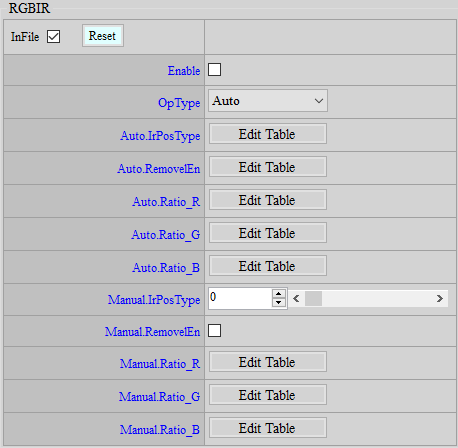
Parameter Description
IrPosType: Change the order of sequence of R, G, B and IR pixels on the sensor. Parameter range: 0 ~ 7.
RemovelEn: Enable the function of IR removal by software.
Ratio_R: Ratio of IR removal (from dark to bright) in R channel. Parameter range: 0 ~ 4095.
Ratio_G: Ratio of IR removal (from dark to bright) in G channel. Parameter range: 0 ~ 4095.
Ratio_B: Ratio of IR removal (from dark to bright) in B channel. Parameter range: 0 ~ 4095.
Adjustment Flow
-
The RGBIR ratio is associated with OB. Before making any adjustment, calibrate OB first.
-
Set the last value of Ratio_R, Ratio_G, and Ratio_B to 64, and fill out all the remaining blanks with 4095. Observe the image now. If there is any color deviation, move on to the next step. (It is suggested that you take a picture of the 24-color Color Checker to see whether any color shift occurs at the lower grayscale region and whether the color at the upper region is accurate.)
-
Keep the last value of the Ratio table as 64 throughout the adjustment process. This prevents brightness from unexpectedly declining in the overexposure region and avoids the occurrence of control parameters for abnormal colors, which fall outside the range of adjustment in normal sensitive region.
-
Keep the values of Ratio_R and Ratio_B unchanged but lower the value of Ratio_G to 2000 (all cells in the table from left to right should be set to 2000, with the exception of the last cell, which should remain 64). In this case, the image will appear greenish.
-
Increase the value of Ratio_G gradually until grayscale region in the image no longer appears greenish.
-
Set the value of Ratio_B to 2000. The image will appear bluish now. Then, as in the case of Ratio_G, increase the value of Ratio_B gradually until grayscale region in the image no longer appears bluish.
-
Similar to Ratio_G and Ratio_B, lower the value of Ratio_R first and then gradually increase the value to make color and gray scale as accurate as possible.
-
If any particular color or any brightness is suspected of color deviation, adjust the ratio of associated brightness, noting that the table from left to right corresponds to brightness from dark to bright.
AE INTRODUCTION
AE aims to control the global brightness of image in an ideal state through the received statistical values. (Return to IQ Tuning Flow Chart)
AE Adjustment
Adjustment Interface
Select “AE” from the menu on the left-hand side, and AE Adjustment Interface will pop up on the main screen to the right.
Parameter Description
-
<AEState>
AE State: AE state control option. When Normal is selected, AE will operate normally. When Pause is selected, AE will pause the current state and will not continue to operate until switched back to Normal.
-
<ManualExposure>
FNx10 : Aperture value (F number) × 10 (ex: F1.8 18).
SensorGain: Sensor gain (1024 = 1x).
ISPGain: ISP digital gain (1024 = 1x).
US: Shutter time, in μs.
-
<AEConverge>
ConvThdIn: Inner convergence interval. When the AE action is in the convergence process, the image will converge to the target +- inner convergence interval before stopping.
ConvThdOut: Outer convergence interval. The starting threshold for AE to start converging again from steady state (the current brightness is outside the range of target +- outer convergence interval).
ConvSpeedX: Convergence speed table X axis, corresponding to the current Cur Y brightness. From left to right, it corresponds to dark to bright, and the two bottom layers in the middle will automatically correspond to the current AE The position of the target, so these two grids do not need to be modified, the default is 470. The first and last grids default to 0 and 2000.
ConvSpeedY: The Y axis of the convergence speed table. After Cur Y corresponds to the X axis, find the corresponding Y axis convergence speed (ratio) [0 ~ 1024], if the number is set too small, AE will react slowly or even fail to converge, if it is set too large, the brightness will change rapidly, but the video will appear to have flickering brightness.
-
<AEStabilizer>
This function can reduce the impact of AE being triggered by local changes in the picture, making the picture brightness more stable.
Enable: This function switch.
DiffThd: The threshold for judging whether the current image has changed with the reference image. If the Y difference exceeds this threshold, it is considered to have changed, and if it is less than this threshold, it is considered to have not changed. The value range is 0~20 (8 bits precision), and the recommended value is 2. It is not recommended to set it too large, which may cause discontinuity when the light gradually brightens or darkens.
Percent: Screen ratio threshold. When AE is converging, if the ratio of the area in the picture that is judged to have changed to the entire picture is less than this value, AE will remain unchanged. The value range is 0~100, and the default value is 50.
-
<AEPlainTbl>
NumOfExpoTblEntry: The number of rows in the exposure table.
ExpoTblEntry : Exposure schedule. From left to right, it sets the aperture (FNx10), shutter (us), total gain, sensor gain, and from top to bottom, it sets from bright to dark.
-
<AEWinWeight>
Weighting PAGEle ID: Photometric weighting table ID. Three weighting tables are supported by default: Average, Center, and Spot.
WindowWeighting: Photometric weighting table.
-
<AELumaWeight>
This function is used to adjust the weight of AE affected by the local brightness of the picture, so that the target brightness of the picture has better adaptability.
Enable: This function switch.
Luma Wgt Points Num: The number of nodes in the brightness weight table, value range: 1 ~ 16.
Luma Wgt: Set the weight of brightness. Set the corresponding weight according to the brightness of the AE statistical value MxN, M x N = 16 x 16, value range: 0 ~ 256, 1x = 256.
Wgt By Luma(x10): Node that sets the brightness value (x10), value range: 0 ~ 2550.
SatCnt Points Num: The number of nodes in the brightness saturation weight table, value range: 1 ~ 16.
SatCnt Wgt: Set the weight of Saturate Count. Set the corresponding weight according to the AE statistical value - MxN brightness greater than SatCnt Threshold, M x N = 16 x 16, value range: 0 ~ 256, 1x = 256.
Wgt By SatCnt: Set the number of nodes for Saturate Count, value range: 0 ~ 256.
SatCnt Threshold: Set the threshold of Saturate count. The larger the value is adjusted, the lower the weight of the bright area is. The value range is: 0 ~ 2550.
Suggested steps:
-
Set different Weights according to the Luma Wgt node.
-
Give different weights to the nodes according to the Saturate Count (SatCnt Wgt).
-
Adjust SatCnt Threshold to determine how many brightness areas are to be included in the SatCnt Threshold count value. The more SatCnt Threshold count values, the lower the weight, otherwise the weight remains doubled.
-
-
<ExposureStrategy>
This area is used to match the AE target settings. When the floating target is used, it adjusts the sensitivity and strength of the floating target in preventing overexposure.
Strategy: Exposure strategy, you can choose AUTO/dark level priority (low light compensation)/bright level priority (strong light suppression).
Weighting: The intensity of the change between dark level priority and light level priority. The greater the weighting, the stronger it is.
UpperNum: The number of nodes floating upwards to the target.
UpperY: The upward floating range. If it is set to 0, it is equivalent to disabling the floating target, and the Target Offset setting set above will be fully referred to.
UpperX: The upward floating range corresponds to the node of BV.
LowerNum: The number of nodes that float downward to the target.
LowerY: The downward floating range. If it is set to 0, it is equivalent to turning off the floating target, and the Target Offset setting set above will be fully referred to.
LowerX: The lower floating range corresponds to the BV node.
Strength: The sensitivity of the anti-overexposure mechanism when floating target. The larger the number, the more sensitive (darker).
Sensitivity: The intensity of the anti-overexposure mechanism when floating target. The larger the number, the darker it is.
Note: The floating target is the target that is automatically calculated after the reference image Histogram changes.
-
<ExposureStrategyEx>
The new version of the exposure strategy setting allows you to design your own anti-overexposure or anti-darkness strategy, and AE will dynamically adjust the SceneTarget based on this strategy.
Enable: Exposure strategy switch. When it is enabled, ExposureStrategy will be invalid.
Mode: Exposure strategy mode, with Count Mode and Target Mode to choose from.
When selecting Count Mode, BT(DT)_ThdY and BT(DT)_Percentx10 are mainly used. The user can specify the percentage of the statistical value above (below) a certain brightness to account for the total number of statistical values.
When selecting Target Mode, BT (DT)_Percentx10 and BT (DT)_Taergetx10 are mainly used. The user can specify how many thousandths of the brightest (darkest) statistical value the average brightness should be close to.
Priority: Exposure strategy priority setting, you can choose dark priority (over-darkness suppression) / bright priority (over-exposure suppression) / HDR_Auto (automatic mode). Note: When switching to HDR_Auto, in addition to BT/DT related parameter settings, you can also fine-tune the parameters of AEStrategyExAdv.
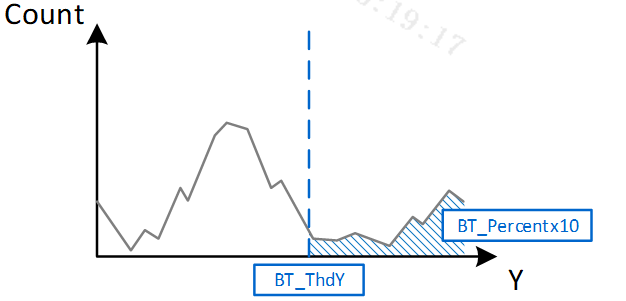
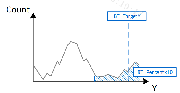
BT_NodeNum: The number of nodes related to Bright Tone parameters.
BT_NodeBV: BV setting of Bright Tone node.
BT_ThdY: Threshold setting of Bright Tone brightness, value range 0 ~ 255. Only used in Count Mode.
BT_Percentx1: Percentage setting of Bright Tone, value range 0 ~ 1000. Used in both Count Mode and Target Mode.
BT_TargetYx10: Target average brightness setting of Bright Tone, value range 0 ~ 2550. Only used in Target Mode.
BT_MaxOffsetDown: The range of AE target floating downward, value range 0 ~ 2550. If set to 0, it is equivalent to turning off the floating target, and the Target Offset setting set above will be fully referred to.
DT_NodeNum: The number of nodes of Dark Tone related parameters.
DT_NodeBV: BV setting of Dark Tone node.
DT_ThdY: Brightness threshold setting of Dark Tone, value range 0 ~ 255. Only used in Count Mode.
DT_Percentx10: Percentage setting of Dark Tone, value range 0 ~ 1000. Used in both Count Mode and Target Mode.
DT_TargetYx10: Target average brightness setting of Dark Tone, value range 0 ~ 2550. Only used in Target Mode.
DT_MaxOffsetUp: The range of AE target floating upward, value range 0 ~ 2550. If set to 0, it is equivalent to turning off the floating target, and the Target Offset setting set above will be fully referenced.
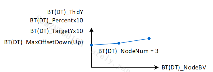
-
<ExposureStrategyExAdv>
HDR Strength Weight 1: Adjust the weight value of dark level priority or bright level priority, the value range is 0~1024.
When it is less than 512, the smaller the value, the more emphasis is placed on Bright Tone Priority.
When it is greater than 512, the larger the value, the more emphasis is placed on Dark Tone Priority.
HDR Strength Weight 2: Adjust the weight value of AE Target, the value range is 0~1024.
When the value is equal to 0, that is, the AE Target weight is invalid, the brightness of the picture is mainly based on the result of Weight1.
When the value is greater than 0, that is, the greater the AE Target weight, the closer the image brightness is to the AE Target.
Suggested steps:
-
Outdoor scene adjustment suggestions: If the user wishes to reduce the overall outdoor brightness, first adjust the HDR Strength weight 1 / 2 = 0 / 0 limit value, and then follow the steps below to adjust:
ExposureStrategyEx – DT Target (decreased) / Percent (increased), the weight ratio of dark level priority is reduced (closer to DT Target)
ExposureStrategyEx – BT Target (decreased) / Percent (unchanged or slightly decreased), the weight ratio of the light level priority is reduced (decrease brightness)
-
Indoor scene adjustment suggestions: If the user expects to increase the overall indoor brightness, first adjust the HDR Strength weight 1 / 2 = 1024 / 0 limit value, and then follow the steps below to adjust:
ExposureStrategyEx – BT Target (increased) / Percent (unchanged), the weight ratio of light level priority is increased (close to BT Target)
ExposureStrategyEx – DT Target (increased) / Percent (unchanged or slightly decreased), the weight ratio of dark level priority is increased (increase brightness)
-
ExposureStrategyEx – After deciding on DT/BT Target & Percentage, users can finally adjust their preferences through HDR Strength weight 1 / 2.
It is recommended to use different target brightness with different ambient brightness (by BV) to achieve the desired effect, while also retaining the user's adjustment flexibility and preferences.
-
-
<AEStrategyExInfo>
GMBlendRatio : The blending ratio of Adaptive Gamma and general Gamma (Gamma setting on the Gamma page), with a value range of 0~1024. It is calculated based on the final SceneTarget, TargetOffset, and the maximum BT_MaxOffsetDown and DT_MaxOffsetUp. When the ratio is less than 512, BTGamma and general Gamma are blended together. When the ratio is greater than 512, DTGamma and general Gamma are blended together. When the ratio is equal to 512, general Gamma is used directly. Please refer to the figure below.
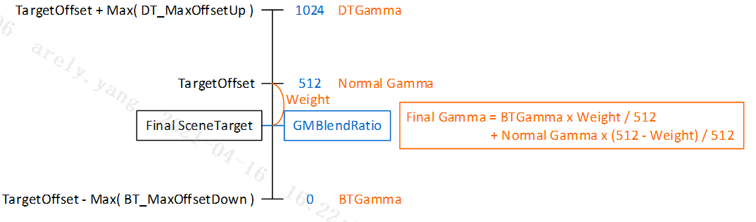
UpperLimitTargetYx10: The Current AE target floating upper limit.
LowerLimitTargetYx10: The current AE target floating lower limit.
BTCntPcentx10: The percentage of statistical values that are currently greater than BT_ThdY in the total number of statistical values.
DTCntPcentx10: The percentage of statistical values that are currently less than DT_ThdY in the total number of statistical values.
BTYx10: The average brightness of the BT_Percentx10 thousandth statistical value before the current brightest.
DTYx10: The average brightness of the DT_Percentx10 thousandth statistical values before the current darkest point.
-
<AdaptiveGamma>
This function needs to be used with StrategyEx so that Gamma can be dynamically adjusted according to SceneTarget to achieve the effect of increasing the dynamic range.
Enable: This function switch, when enabled, the normal Gamma will be used directly.
BTGamma: When GMBlendRatio is less than 512, BTGamma will be mixed with general Gamma according to GMBlendRatio.
DTGamma: When GMBlendRatio is greater than 512, DTGamma will be mixed with general Gamma according to GMBlendRatio.
-
<ExposureMode>
Exposure Mode: AE status control option, select Auto for fully automatic exposure, AV_Mode for aperture priority, SV_Mode for gain priority, TV_Mode for shutter priority, and M_Mode for full manual.
-
<AETarget>
Target Points Num: The number of nodes set for AE target (different AE targets are set according to different ambient brightness values (BV)).
Target Offset: AE target of each node.
Target BV: BV value of each node.
-
<EVComp>
EVComp: Denominator of the +-ev brightness compensation function.
Grad: Numerator of the +-ev brightness compensation function.
-
<ExposureLimit>
MinShutter: Minimum shutter time.
MaxShutter: Maximum shutter time.
MinFNx10: Minimum aperture value (the larger the number, the smaller the aperture).
MaxFNx10: Maximum aperture value.
MinSensorGain: Minimum sensor gain.
MinISPGain: Minimum ISP digital gain.
MaxSensorgain: Maximum sensor gain.
MaxISPGain: Maximum ISP digital gain.
-
<Flicker>
Flicker: Anti-flicker setting corresponding to a specific frequency. You can choose Disable, 50Hz, 60Hz, and Auto.
-
<FlickerEx>
Enable: Enable/disable the new version detection anti-flicker function. When the new version is enabled, the old version will be invalid.
OpType: Detects the anti-flicker working mode, with Auto and Manual modes available. When set to Auto, it will automatically switch when it detects that the Flicker mode needs to be switched. It is recommended to use Auto.
AmpSensitivity: Adjust the sensitivity of anti-flicker detection (the larger the value, the more sensitive it is). The value range is 1~100, and the recommended default value is 70.
ScoreThd: The threshold for triggering automatic switching of FlickerType in Auto mode. If Score is less than this threshold, ValidTimes will increase by 1. If Score is greater than this threshold, ValidTimes will be reset to 0. The value range is 1~100, and it is recommended to be set to 50.
RefreshCycles: Adjust the update rate of the score calculated by the detection anti-flicker. This parameter represents how many cycles the score is updated. A cycle is usually about 4 to 7 frames. The value range is 1 to 10. The larger the value, the more reliable the score is, but the longer it takes. The recommended default value is 3.
ValidTimesThd: In Auto mode, when ValidTimes reaches ValidTimesThd, the algorithm will automatically switch to another Flicker mode. The value range is 1 ~ 10. The larger the value, the less likely it is to misjudge, but the longer it takes. The recommended default value is 2.
Flicker: Detect anti-flicker mode, the modes are 60Hz = 0 and 50Hz = 1.
-
<FlickerInfo>
IsEffective: Get whether the current anti-flicker detection is effective (1: effective value, 0: invalid value).
FlickerType: Get the current anti-flicker detection mode, the modes are 60Hz = 0 and 50Hz = 1.
Score: Get the degree score of the current anti-flicker detection effective mode. If the score is high, it is determined to be the current anti-flicker rate mode. If the score is low, it is determined to be another anti-flicker rate mode.
-
<RGBIR AE>
Enable: Enable/disable RGBIR AE.
MaxYWithIR: The maximum allowable average brightness of the bright area before subtracting IR.
MinISPGainCompRatio: The maximum ratio of raw brightness compensation through ISP gain. The smaller the number, the greater the degree of compensation.
-
<DebugLev>
AE Debug Level: Set the output settings of AE Debug log (0: disable, 1: Exposure, 2: Algo parameters, 4: Algo statistics, 32: API debug, 64: Exposure-2).
-
<AE HDR Ratio> – HDR mode only
AE HDR Poionts Num: Set the number of nodes for changing the HDR long and short exposure ratio.
HDR Ratio: Set the exposure ratio of HDR long and short exposure (1024 = 1x).
By Total Gain: The total gain horizontal axis where the HDR exposure ratio changes according to the total gain. It is recommended to use the default value (default value: 1024, 2048, 4096, 8192...).
Note: This function will be removed in APIVer 1.13, and its variables will be integrated into the < AE HDR Dynamic Ratio > data structure.
-
<AEPlainShortTbl> – HDR mode only
NumOfExpoTblEntry: The number of columns (rows) in the short exposure exposure table.
ExpoTblEntry : Exposure schedule. From left to right, it sets the aperture (FNx10), shutter (μs), total gain, and sensor gain. From top to bottom, it sets the brightness to darkness.
-
<ManualShortExposure> – HDR mode only
FNx10: Aperture value (F number) × 10 (ex: F1.8 à 18).
SensorGain : Sensor gain (1024 = 1x).
ISPGain: ISP digital gain (1024 = 1x).
US: Shutter time, in μs.
-
<AE HDR Dynamic Ratio>
This function Auto mode only supports HDR mode, Linear mode needs to be set to Manual mode
OpType: Set the working mode of HDR dynamic range, which can be selected from Auto and Manual modes. If set to Auto, the HDR dynamic range value will be automatically analyzed according to the scene.
AE HDR Points Num: Set the number of nodes for changing the HDR long and short exposure ratio. (Manual mode only)
HDR Ratio: Set the exposure ratio of HDR long and short exposure (1024 = 1x). (Manual mode only)
By Total Gain: The HDR exposure ratio changes according to the total gain. It is recommended to use the default value (default value: 1024, 2048, 4096, 8192...). (Manual mode only)
ExpoRatioSpeed: Set the convergence smoothing speed of the HDR dynamic range, value range: 1 ~ 1024. (Auto mode only)
ExpoRatioTolerance: Set the convergence tolerance of HDR dynamic range, value range: 0 ~ 1024. (Auto mode only)
ExpoRatioMin: Set the minimum value of HDR dynamic range, value range: 1024 ~ 65535. (Auto mode only)
ExpoRatioMax: Set the maximum value of HDR dynamic range, value range: 1024 ~ 65535. (Auto mode only)
OpTypeShortExpoTab: Set the working mode of the maximum exposure value of short exposure, which can be selected in Auto and Manual modes. If set to Auto, the maximum exposure value of short exposure will be filled in according to sensor driver - short shutter max.
ShortShutterMax: When enOpTypeShortExpTab is equal to manual mode, this parameter is used to set the maximum short exposure value.
-
<AE HDR Dynamic Ratio Info>
Exposure Ratio: Read the current HDR dynamic range value.
IsChange: Read whether the current HDR dynamic range has changed, 0: unchanged, 1: changed.
AWB INTRODUCTION
Color shift often occurs in gray scale under different light sources because R, G, B pixels share different photographic characteristics. AWB aims to automatically generate R and B gains for compensation, so that the R, G and B values are as similar to one another as possible in the gray scale region.
AWB Adjustment
The AWB statistics are obtained by dividing the screen into 128x90 equal blocks, with each block containing R/G/B value. The default horizontal axis is subsampled to reduce the computation, and hence the statistical values actually being computed are 64×90. If you want to check the statistics of a certain scene, open the AWB Analyzer plugin, and click “Update” for the current statistics. The horizontal axis represents (R/G)×100, and the vertical axis (B/G)×100. Therefore, each block would generate a set of coordinates by the calculation of its own R, G, and B values, and the drop point on the chart is shown in green dots, as illustrated in Figure below.
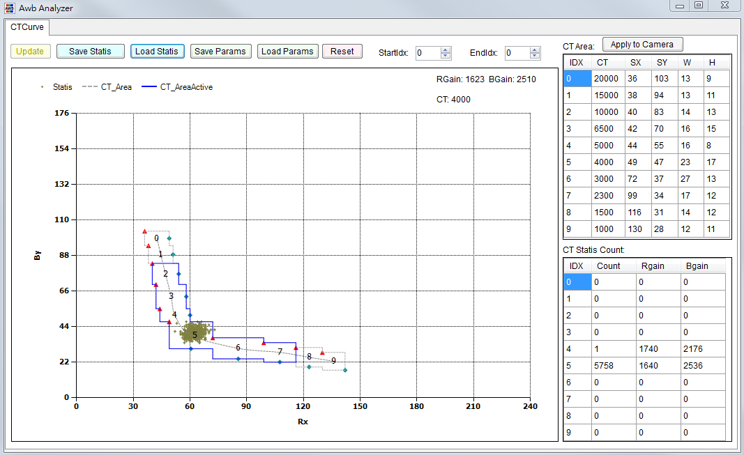
Adjustment Interface
Select “AWB” from the menu on the left-hand side, and AWB Interface will pop up.
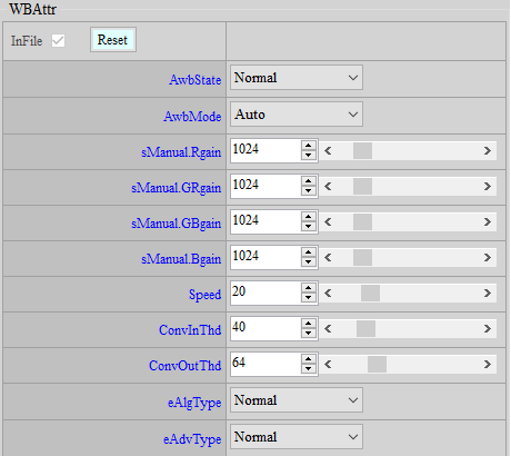
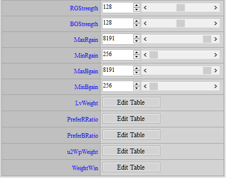
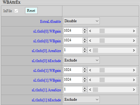
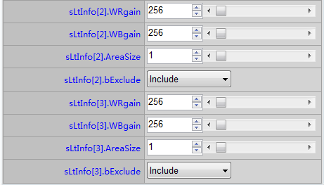
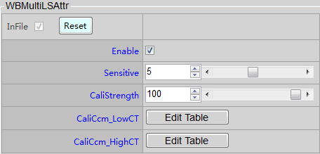
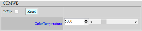
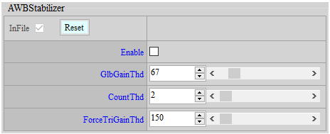
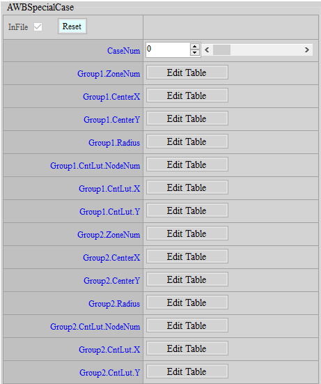
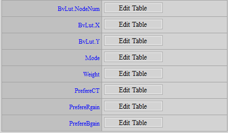
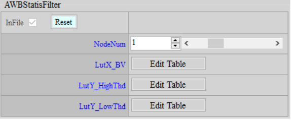
Parameter Description
-
<WBAttr>
Recommended parameters
AwbState: AWB status control option. When Normal is selected, AWB will operate normally. When Pause is selected, AWB will pause at the current state and will not continue to operate until it is switched back to Normal.
AwbMode: WB status control option, select Auto for AWB, select Manual for MWB.
sManual.R/GR/GB/Bgain: When AwbMode selects Manual, these four gain values will be directly applied, with a value range of 0 ~ 8191 (1024 is 1 times).
Speed: AWB convergence speed control, value range 1 ~ 100, the larger the value, the faster the convergence, the default value is 20.
ConvInThd: Convergence interval size control, value range 0 ~ 255, the larger the value, the easier it is to converge, but it is easy to have a large gap with the target. If it is too small, AWB may become unstable. The default recommended value is 32.
ConvOutThd: The threshold control for jumping out of the convergence state and recalculating the white balance. The value range is 0 ~ 255. It is not recommended to set it too large, otherwise when the light source changes, the white balance cannot be recalculated, which will cause color cast. The default recommended value is 64.
eAlgType: White balance algorithm mode selection, there are four modes:
-
GrayWorld: Calculate WB gain using all statistics.
-
Normal: Calculate WB gain based on the statistical values in the 2 to 3 color temperature boxes with the highest number of points.
-
Balance: Calculate WB gain based on the statistical values of all colors falling into the valid color temperature box.
-
Focus WB gain calculation will tend to be based on a single color temperature.
eAdvType: WBAttrEx function switch. WBAttrEx will only work when Advance is selected. The default setting is Default and WBAttrEx is not used.
RG/BG Strength: A global gain for R and B. The final calculated R and B gains will be multiplied by a gain. The value range is 0 ~ 255, and 128 is 1 times.
MaxRgain/MaxBgain: High color temperature R, B gain limit, value range 0 ~ 8191.
MinRgain/MinBgain: Low color temperature R, B gain limit, value range 0 ~ 8191.
LvWeight: Color temperature weight setting under each ambient brightness. The larger the weight, the higher the proportion of this color temperature when calculating R and B gain. The value range is 1~255.
PreferR/Bratio: R and B ratio settings under various ambient brightness. This ratio will be multiplied by the target R and B gains. The value range is 1 ~ 255 .
u2WpWeight: The weight of determining the reference white point. The higher the weight, the easier it is to be selected as the reference white point. The value range is 1~400, and the default is 100. The horizontal axis 1~10 represents the color temperature frame of AWB index0~9.
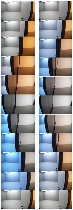
WeightWin: Divide the image into 9x9 areas, and give each area a weight. The greater the weight, the more the white balance will tend to gray that area. The value range is 0 ~ 16. The weight is relative, not absolute, that is, setting all to 1 is basically the same as setting all to 16. When the lens is fixed and you know clearly which area in the image you want to use for white balance or not, you can use this function to make adjustments.
-
-
<WBAttrEx>
The WBAttrEx series of parameters only take effect when eAlgType is set to Advance. It mainly allows users to customize several special boxes and choose whether to include or exclude the statistical values that fall into this special box. There are a total of 4 groups of settings available.
ExtraLtEnable: Special color temperature frame function switch, needs to be set to Enable special color temperature frame to work.
sLtInfo.WR/Bgain: The R and B gains represented by the center coordinates of the special color temperature frame. The value range is 0 ~ 8191. The conversion method is to open the AWB Analyzer to analyze the statistical value landing point, move the cursor to the center of the area to be selected to view the coordinates. Assuming Rx = 40, By = 60, first divide the coordinates by 100 (0.4, 0.6), then take the reciprocal (1/0.4, 1/0.6), and finally multiply by the gain base 1024 (WRgain = 2560, WBgain = 1706) to complete the conversion of the special frame center position.
sLtInfo.AreaSize: The width and height of the special box, the value range is 1 ~ 32. When set to 32, it means that it extends 16 from the center to the top, bottom, left and right.
sLtInfo.bExclude: Special box mode selection. Selecting Include means that the statistical values falling into the special box will also be used for reference. Selecting Exclude means that the statistical values falling into the special box will be ignored.
-
<WBMultiLSAttr>
This function is only effective when eAlgType is set to Focus. At this time, the R and B gains of AWB will try to focus on the reference white point. If you encounter a mixed light scene, the color deviation of the side far from the reference white point will be quite obvious. If you want to reduce the color deviation, you can turn on this function, but the side effect is that the hue of other colors will change. The following is a comparison of the difference before and after turning on this function.
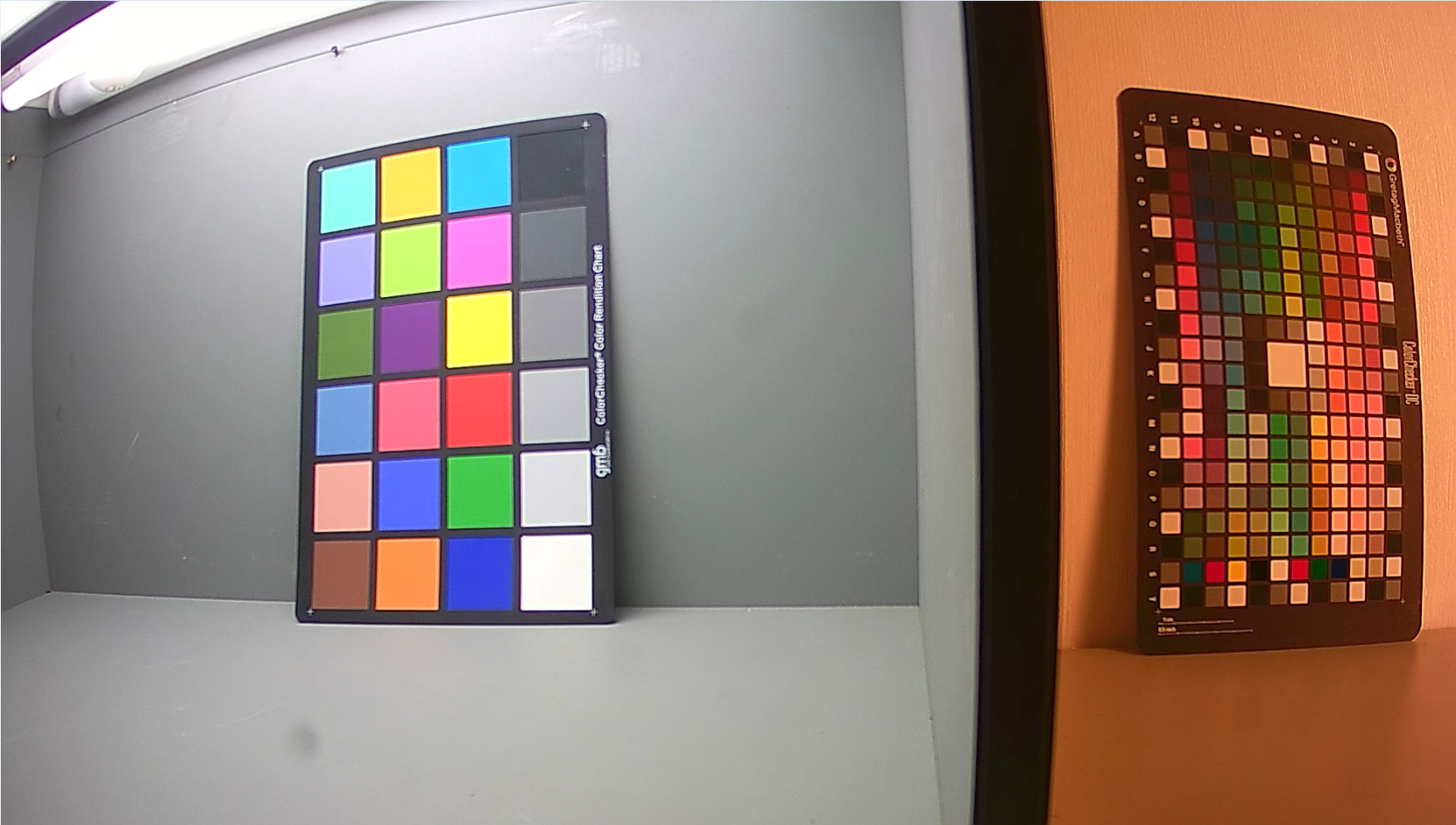
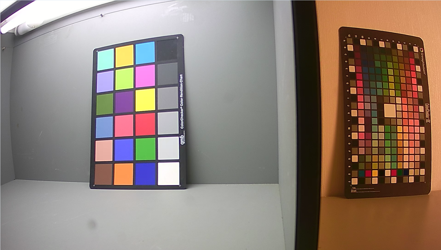
Enable: Switch the mixed light color cast correction function. When it is turned on, the color cast area can be improved, but the color of the gray area in AWB will be slightly cast.
Sensitive: Adjust the mixed light judgment sensitivity, the value range is 1 ~ 10, the larger the value, the easier it is to judge the scene as a mixed light scene.
CaliStrength: Mixed light color cast correction intensity control, the value range is 0 ~ 100, 100 is 1 times, which is the original intensity of CaliCcm.
CaliCcm_LowCT: When mixing light, when AWB chooses to make high color temperature gray, this CCM will be selected to reduce the serious color cast problem in the low color temperature area. Currently, only the first and third rows are open for adjustment. Adjusting the second row will have no effect. This CCM intensity is mainly applied when the two mixed light sources are StartInd and EndInd respectively. The actual applied intensity will be determined by the ratio of the distance between the two light sources to the distance between StartInd and EndInd.
CaliCcm_HighCT: When mixing light, when AWB chooses to gray low color temperature, this CCM will be selected to reduce the serious color cast problem in the high color temperature area. Currently, only the first and third rows are open for adjustment. Adjusting the second row will have no effect. Adjusting the second row will have no effect. This CCM intensity is mainly applied when the two mixed light sources are StartInd and EndInd respectively. The actual applied intensity will be determined by the ratio of the distance between the two light sources to the distance between StartInd and EndInd.
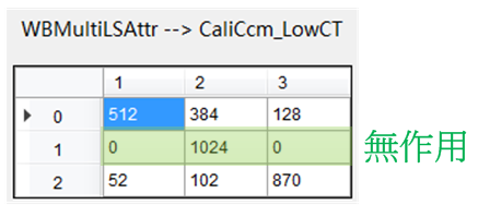
Adjust CaliCcm suggestions, taking CaliCcm_LowCT as an example:
-
Set the light box to D65 (if there is a light source closer to StartIdx, you can use that light source) and let AWB gray it out.
-
Switch AWB to PAUSE.
-
Switch the light box to F (if there is a light source closer to EndIdx, you can use that light source), adjust CaliCcm_LowCT, and switch back to the previously gray light source from time to time during adjustment to see if the normal color is too biased. Adjust until both sides are acceptable.
-
-
<CTMWB>
This function is only effective when CT Manual is selected for AwbMode in WBAttr. Users can apply the corresponding WB gain by selecting the color temperature.
ColorTemperature: Set the specified color temperature. The value range is 1000 ~ 20000.
-
<AWBStabilizer>
When the environment is stable, but you find that AWB is constantly triggered, causing the image color to change back and forth, it is recommended to turn on this function to make AWB changes more stable.
Enable : Switch of AWB Stabilizer.
GlbGainThd: Threshold control for overall WB gain change. When AWB is in the convergence state and needs to be re-triggered, in addition to meeting the original conditions (ConvOutThd), the overall WB gain change needs to exceed this threshold before it will be re-triggered. The value range is 0 ~ 512. It is recommended that this value be set to the same as ConvOutThd or smaller. The default value is 64.
CountThd: The number of times to re-trigger AWB. When this value is 2, the re-trigger condition must be met three times in a row to re-trigger AWB, otherwise AWB will remain in a stable state. The value range is 0 ~ 100. It is recommended that this value not be set too high, because it will delay the reaction time of AWB being triggered. The default value is 2.
ForceTriGainThd: To prevent the AWB reaction time from slowing down due to CountThd when the ambient light source color temperature changes dramatically, we define a gain threshold for forced triggering. As long as the gain change meets the conditions for re-triggering AWB, and the change is greater than this threshold, CountThd will be ignored and AWB will be directly triggered. The value range is 0 ~ 8191. The default value is 150.
-
<AWBSpecialCase>
This function allows users to define a case using three conditions (Group1, Group2, and BvLut) and determine the corresponding behavior of AWB when the case is achieved, which is used to improve the accuracy of AWB in specific scenarios. A total of four cases can be defined, and the effects of each case will be superimposed.
CaseNum: The number of cases to be defined. A set of case settings is for a specific scenario. The value range is 0 to 4. Setting it to 0 means that this API is invalid.
Group1 series parameters are used to define the first condition. Users can define multiple zones, and the algorithm will count the percentage of AWB statistics falling into all zones to the total statistics, and then look up the table to get the compliance rate of Group1.
Group1.ZoneNum : The number of zones to be defined. The algorithm will analyze the percentage of AWB statistics that fall into all zones to the total number of statistics. The value range is 0 ~ 8. Setting 0 means that this condition is met unconditionally.
Group1.CenterX: Determines the x-coordinate of the center point of each zone on the R/GB/G plane. The value range is 0 ~ 1023.
Group1.CenterY: Determines the y coordinate of the center point of each zone on the R/GB/G plane. The value range is 0 ~ 1023.
Group1.Radius: Determines the radius of each zone. The value range is 0 ~ 20.
Group1.CntLut.NodeNum: Determines the number of nodes that CntLut will use. The value range is 0 ~ 4.
Group1.CntLut.X: Determines the x value of the CntLut node, which represents the percentage of the total number of statistical values that fall into all zones. The algorithm will analyze the statistical value percentage of Group1 to look up this table and obtain the Group1 condition compliance rate Group1.CntRatio. The value range is 0 ~ 100.
Group1.CntLut.Y: Determines the y value of the CntLut node, representing the ratio value. The algorithm will analyze the statistical value percentage of Group1 to look up this table and obtain the Group1 condition compliance rate Group1.CntRatio. The value range is 0 ~ 100.
Group2 is used in the same way as Group1. For related instructions, please refer to Group1. The algorithm will obtain the conditional compliance rate of Group2, Group2.CntRatio, based on the Group2 series settings.
BvLut allows users to define specific scenes with an additional dimension of ambient brightness, for example, this condition can be used to distinguish between outdoor daytime and indoor scenes. The algorithm will look up the table based on the Bv value to obtain the final brightness condition compliance rate BvRatio.
BvLut.NodeNum : The number of BvLut nodes. The value range is 0 ~ 4, and 0 means that this condition is met unconditionally.
BvLut.X: Determines the x value of the BvLut node, representing Bv. The value range is -81920 ~ 245760.
BvLut.Y: Determines the y value of the BvLut node, representing the compliance rate. The value range is 0 ~ 1024.
The compliance rates of the three conditions for each case will eventually be integrated into one value, representing the compliance rate CaseRatio of this case.
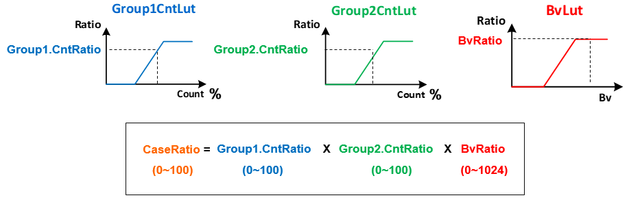
This API provides three modes. Users can choose the action to be performed when a case is fulfilled. The intensity is determined by the CaseRatio.
Mode: The behavior mode selected when the case is completed, the value range is 0 ~ 2.
0: WeightCtrl mode
1: PreferCT mode
2: PreferGain mode
Weight: When Mode is 0, it is effective. The color temperature frame will apply this weight setting according to CaseRatio. The value range is 0 ~ 1024.
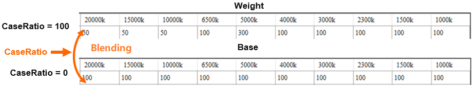
PreferCT: When Mode is 1, the original Target WB gain will be mixed with the WB gain corresponding to CaseRatio and PreferCT to become the new Target WB gain. The value range is 0 ~ 20000.
PreferR/Bgain : Valid when Mode is 2. The original Target WB gain will be mixed with PreferR/Bgain according to CaseRatio to become the new Target WB gain. The value range is 0 ~ 8191.
-
<AWBStatisFilter>
This function can set the effective brightness range of the statistical value according to BV to exclude the statistical values that are too dark or too bright, so as to prevent AWB from being affected by noise or overexposed areas.
NodeNum: Set the number of nodes in the lookup table. The value range is 0 ~ 4. If it is set to 0, the default effective brightness range of 4 ~ 224 will be used.
LutX_BV: Set the node x coordinate of the lookup table, that is, BV. The value range is -81920 ~ 245760.
LutY_HighThd: Set the node Y coordinate of the lookup table, which is the maximum brightness limit. If any value in the RGB statistical value exceeds this limit, the statistical value will be ignored. The value range is 0 ~ 255.
LutY_LowThd: Set the Y coordinate of another lookup table node, which is the minimum brightness limit. If any value in the RGB of the statistical value is lower than this limit, the statistical value will be ignored. The value range is 0 ~ 255. Note that LowThd must be smaller than HighThd.
-
<DebugLev>
AWB Debug Level: Set the output settings of AWBDebug log.
1: show simple algo paramaters
2: always show detail algo parameters
3: show detail algo parameters
7: User Parameters
AWBInfo
-
<AWBInfo>
This interface can display the current AWB related information. Click ReadPage to update in real time.
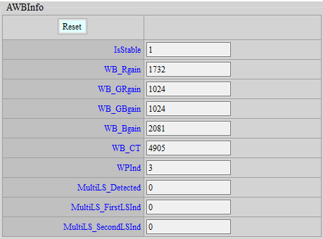
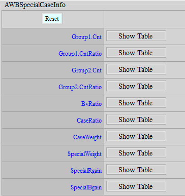
IsStable: Whether the current AWB is in a stable state.
WB_Rgain: R gain currently used by WB.
WB_Grgain: GR gain currently used by WB.
WB_Gbgain: GB gain currently used by WB.
WB_Bgain: B gain used by current WB.
WB_CT: The current ambient color temperature.
This function requires that the values displayed in the following items are meaningful only when eAlgType is selected as Focus.
WPInd: The current reference white point Index.
MultiLS_Detected: Displays whether a mixed light scene is detected.
MultiLS_FirstLSInd: Displays the first mixed light source index×2. The actual light source index must be divided by 2. For example, when the index is 8, the actual index is 4. When the index is 9, the actual index is 4.5. If there is .5, it means that this light source is judged to fall between the color temperature boxes of 4 and 5.
MultiLS_SecondLSInd: Displays the second largest mixed light source index×2. It must be divided by 2 to get the actual light source index. For example, when the index is 8, it is actually 4, and when the index is 9, it is actually 4.5. If there is .5, it means that this light source is judged to fall between the color temperature boxes of 4 and 5.
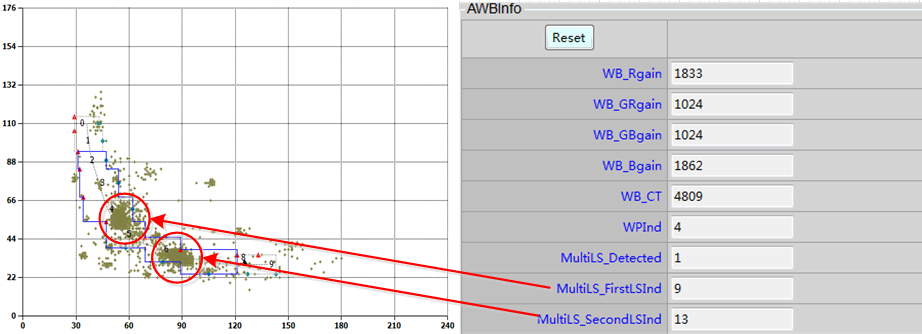
-
<AWBSpecialCaseInfo>
This API allows users to understand the current statistics of SpecialCase API.
Group1.Cnt: Displays the total number of Group1 statistical value points for each case.
Group1.CntRatio: Displays the total number of Group1 statistical value points for each case and the ratio obtained by querying Group1.CntLut. The value range is 0~100.
Group2.Cnt: Displays the total number of Group2 statistical value points for each case.
Group2.CntRatio : Displays the total number of Group2 statistical value points of each case and the ratio obtained by querying Group2.CntLut. The value range is 0~100.
BvRatio: Displays the ratio of each case after searching BvLut according to Bv. The value range is 0 ~ 1024.
CaseRatio: Displays the ratio of each case after integrating Group1.CntRatio, Group1.CntRatio and BvRatio. The value range is 0 ~ 100.
CaseWeight: Displays the CaseWeight of each case obtained through CaseRatio. If the Mode is not 0, the CaseWeight will be 100, which means it has no effect.
SpecialWeight: Integrate the four sets of CaseWeight into one set of SpecialWeight.
SpecialR/Bgain: Displays the RB gain to be mixed with the Target WB gain in each case.
AF INTRODUCTION
AF aims to focus the image in an ideal state through the received statistical values.
AF Adjustment
Adjustment interface
Click AF in the left menu and the AF adjustment interface will appear.
Parameter Description
-
<AF_HWROIMODE>
Mode: ROI mode control option. Select Normal to cut into 16 groups of ROIs. The window size and position can be divided arbitrarily. Select Matrix to cut into 16*N groups of ROIs. The window size and position are slightly restricted.
VerticalBlockNumber: It takes effect only when Mode is Matrix and can be cut into 16*N groups of ROI (N = VerticalBlockNumber).
-
<AF_HWWIN>
Win: 16 sets of ROI coordinates, in the order of x_start, y_start, x_end, y_end.
-
<AF_HWFILTERATTR>
IIR1: IIR high filter coefficient.
IIR1_Clip: Input/output limit of IIR high filter coefficient.
IIR2: IIR low filter coefficient.
IIR2_Clip: Input/output limiting of IIR low filter coefficient.
IIR1_E1_En: IIR high cascade first stage filter switch.
IIR1_E1: IIR high cascade first stage filter coefficients.
IIR1_E2_En: IIR high cascade second stage filter switch.
IIR1_E2: IIR high cascaded second stage filter coefficients.
IIR2_E1_En: IIR low cascade first stage filter switch.
IIR2_E1: IIR low cascade first stage filter coefficients.
IIR2_E2_En: IIR low cascade second stage filter switch.
IIR2_E2: IIR low cascade second stage filter coefficients.
-
<AF_HWFILTERSQ>
SobelYSatEn: Sobel filter Y threshold switch.
SobelYThd: Sobel filter Y threshold, which takes effect only when SobelYSatEn is true. Brightness less than this value will be included in the Sobel filter calculation.
IIRSquareAccEn : IIR filter enhancement control switch.
SobelSquareAccEn: Sobel filter enhancement control switch.
IIR1Thd: IIR high filter input threshold, this value will be subtracted before output.
IIR2Thd: IIR low filter input threshold, this value will be subtracted before output.
SobelHThd: Sobel H filter input threshold, this value will be subtracted before output.
SobelVThd: Sobel V filter input threshold, this value will be subtracted before output.
AFTblX: The horizontal axis node of the IIR/Sobel filter nonlinear mapping, which accumulates in powers of two.
AFTblY: The vertical axis node for nonlinear mapping of IIR/Sobel filter.
-
<AF_ATTR>
State: State control option. Selecting Normal will cause the system to operate normally. Selecting Pause will cause the system to pause at the current state until it is switched back to Normal.
Mode: State control option. Select Manual to directly set the motor position. Select Auto to choose different algorithms for focusing.
ManualMotorPos: This function takes effect only when Mode is Manual, and directly sets the motor position.
Algo: This function takes effect only when Mode is Auto. Currently two algorithms are supported.
OneShot: Go through all the locations, then go to the location with the highest statistic.
Continuous: This function will dynamically detect changes in the environment and refocus if there are any changes.
-
<AF_MOTOR>
MinMotorPos: The minimum position that the Motor can move to.
MaxMotorPos : The maximum position that the Motor can move to.
MinMotorStep: The minimum step that the Motor can move in one frame.
MaxMotorStep : The maximum step that the Motor can move in one frame.
-
<AF_ACC_WEIGHT>
WinNumX: The total number of windows in the X direction
WinNumY: The total number of windows in the Y direction.
EqualWinWgtEn: Statistical value equal weight switch.
WinWgt: Statistical value weight table, only effective when EqualWinWgtEn is false.
IIRHBlendEn: IIRH blend switch, and blend according to the following three values.
IIRHWgt_FirstBlendIIRL: IIRH is mixed with IIRL first, this value is the IIRH ratio.
IIRHWgt_SecondBlendSBLV: IIRH is blended with SobelV again, this value is the IIRH ratio.
IIRHWgt_ThirdBlendSBLH: IIRH is finally mixed with SobelH, and this value is the IIRH ratio.
-
<AF_ONESHOT> - It takes effect only when Algo is OneShot.
AccSel: Statistical value type.
MotorStep: The movement step of the Motor in each frame.
-
<AF_CONTINUOUS_SCENE_CHANGE> - It takes effect only when Algo is Continuous.
PreAcc series: Check whether to refocus when AF is in action, based on the statistical difference between the current frame and the previous frame.
PreAccSel: AF statistic type.
PreAeAccDiffThOft: AE statistical value (Luma) difference ratio threshold.
PreAeAccDiffThSlp: The additional slope of AE statistic (Luma) difference ratio threshold, increasing the threshold according to motor step.
PreAeAccCntThOft: The ratio threshold of the total number of windows that the AE statistical value (Luma) meets.
PreAeAccCntThSlp: The additional slope of the window ratio threshold that the AE statistical value (Luma) meets, increasing the threshold according to the motor step.
PreAfAccDiffThOft: AF statistics (PreAccSel) difference ratio threshold.
PreAfAccDiffThSlp: The additional slope of the AF statistic (PreAccSel) difference ratio threshold, increasing the threshold according to the motor step.
PreAfAccCntThOft: The ratio threshold of the total number of windows that the AF statistics (PreAccSel) meets.
PreAfAccCntThSlp: The additional slope of the window ratio threshold that the AF statistic (PreAccSel) meets, increasing the threshold according to the motor step.
FocusAcc series: Check whether to refocus when AF stops, based on the statistical difference between the current frame and the previous focus end.
FocusAccSel : AF statistic type.
FocusAeAccDiffTh: AE statistical value (Luma) difference ratio threshold.
FocusAeAccCntTh: The ratio threshold of the total number of windows that the AE statistic (Luma) meets.
FocusAfAccDiffTh: AF statistics (FocusAccSel) difference ratio threshold.
FocusAfAccCntTh: The ratio threshold of the total number of windows that the AF statistics (FocusAccSel) meets.
StableCntTh: Continuous stable frame rate threshold. If this value is exceeded, the environment is considered stable and the motor starts moving to focus.
-
<AF_CONTINUOUS_SCENE_CHANGE> calculation description
AF triggers are divided into 2 categories:
-
Check whether to refocus when AF is in effect:
Pre AE Acc: Compare the AE statistical value difference between the current frame and the previous frame, range 0 ~ 99%.
Pre AF Acc: Compare the AF statistics between the current frame and the previous frame, range 0 ~ 99%.
AE or AF is established, focus is triggered.
In addition, the PreAcc series has an additional Slp that can be adjusted in order to dynamically adjust with the motor step size.
Th is calculated as: Oft + motor step*Slp. The range of this total Th is 0 ~ 99%.
-
Check whether to refocus when AF stops:
Focus AE Acc: Compares the AE statistics difference between the current frame and the last focused frame, range 0 ~ 99%.
Focus AF Acc: Compares the AF statistics between the current frame and the last focused frame, range 0 ~ 99%.
When either AE or AF is established, focus is triggered.
There are two types of thresholds, both of which must be met at the same time to trigger:
-
Diff Th: The statistical value difference percentage is greater than this value, which is triggered. The range is 0 ~ 99%.
-
Cnt Th: The percentage of window difference. It is triggered when the difference is greater than this value. The range is 0 ~ 99%. The preset window number is usually 16.
For example, there are 5 windows with statistical values that differ by more than 30% in the picture. Assume that the conditions are set as follows:
-
Diff Th = 25, Cnt Th = 30 (equivalent to 4.8 windows), this condition will be triggered.
-
Diff Th = 25, Cnt Th = 35 (equivalent to 5.6 windows), this condition will not be triggered.
Therefore, the lower the Th adjustment, the easier it is for AF to be triggered.
It is recommended to use u-art for adjustment and enable AF debug level 16 or 128 to see the changes in statistical values.
-
-
<AF_CONTINUOUS_SEARCH_START> - It takes effect only when Algo is Continuous.
SearchMotorStep: The moving step of the Motor in each frame.
SearchMotorDirByPosTh: Determine the moving direction based on the current motor position. If it is greater than this value, it moves to a smaller position, and vice versa.
SearchAccSel: Statistical value type.
-
<AF_CONTINUOUS_SEARCH> - It takes effect only when Algo is Continuous.
MinMaxAccRatioPeakThOft: The minimum and maximum statistical value difference ratio threshold, used to determine the peak.
MinMaxAccRatioPeakThSlp: The minimum and maximum statistical value difference ratio threshold slope, which can be lowered based on the total path.
AccDecCntPeakTh: The threshold of the number of consecutive decreases in the statistical value, used to determine the peak.
NowFakeMaxAccRatioPeakTh: The statistical value decrease ratio threshold, used to determine the peak.
AccDecCntWrongDirTh: The threshold of the number of consecutive decreases in the statistical value, used to determine whether the person is going in the wrong direction.
NowFakeMaxAccRatioWrongDirTh: The statistical value decrease ratio threshold, used to determine whether it is going in the wrong direction.
Ps1. The peak condition is if((MinMaxAccRatioPeakThOft, MinMaxAccRatioPeakThSlp) && (AccDecCntPeakTh || NowFakeMaxAccRatioPeakTh) )
Ps2. The condition for judging wrong direction is if(AccDecCntWrongDirTh || NowFakeMaxAccRatioWrongDirTh)
-
<AF_Adjust> - It takes effect only when Algo is Continuous.
AFTable: Records VCM focus positions. 1→100cm position, 2→80cm position, 3→60cm position, 4→40cm position, 5→20cm focus position.
Adjustment steps:
-
Get a chart that can fill the focus frame when the camera is 100cm away from the chart.
-
Algo: Continuous → OneShot;
AFOneShot: MotorStep is set to 10 (the smaller the value, the finer the search).
- Set DebugLevel to 1, see where the Peak is finally found, and fill in the table (the farther the location, the smaller the VCM location number).
SearchMotorStep_ADJ : Adjust AFContinuous_SearchStart:MotorStep speed according to AFTable (far to near, slow to fast).
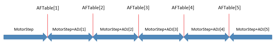
FocusAfAccCntTh_ADJ : Adjust AFContinuous_SceneChange:FocusAfAccCntTh according to AFTable (suggestion: from far to near, the conditions gradually relax).
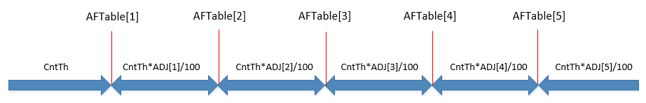
FocusAfAccDiffTh_ADJ : Adjust AFContinuous_SceneChange:FocusAfAccDiffTh according to AFTable (suggestion: from far to near, the conditions gradually relax).
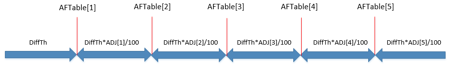
CheckMotionCnt: The number of frames to check the AF trigger condition.
Motion series: Used to check whether the picture is still. Only when it is still will the AF trigger condition be checked.
MotionAeAccDiffTh: AE statistical value (Luma) difference ratio threshold.
MotionAeAccCntTh: The ratio threshold of the total number of windows that the AE statistics (Luma) meets.
MotionAfAccDiffTh: AF statistics (PreAccSel) difference ratio threshold.
MotionAfAccCntTh: The ratio threshold of the total number of windows that the AF statistics (PreAccSel) meets.
WinWgt: Trigger weight table.
UnStableCntTh: Do not check the frames of several unstable images.
AEStableCntTh: Continuously check several AE stable frames before performing AF.
AfAccDelay: Delay in the effectiveness of statistical values.
-
-
<FDAF> - It takes effect only when Algo is Continuous.
Enable: Enable the switch of FDAF.
FDStableCntTh: Checks for a certain number of consecutive stable frames before performing AF.
-
<AF_DetectFlatZone> - It takes effect only when Algo is Continuous.
Enable: Enable the switch to detect flat area.
FDStableCntTh: When the statistical values are less than Th during the SearchPeak process, it is judged as a flat area.
MotorPos: The position to which the VCM moves when it is judged to be a flat area.
-
<DEBUG_LEV>
The relevant debug log can be printed out through U-art.
Level Description 0 Disabled. 1 FPS, current motor position. 2 motor change flag, target motor position, window change flag. 4 current motor position, all window acc value. 8 current motor position, weight sum acc value. 16 current motor position, AF_CONTINUOUS_SCENE_CHANGE acc log. 32 AF_ONESHOT status. 64 AF_CONTINUOUS status. 128 AF_CONTINUOUS_SCENE_CHANGE flag. 256 AF_CONTINUOUS_SEARCH acc min/max/ratio/IncCnt/DecCnt. 512 AF_CONTINUOUS_SEARCH peak flag. 1024 AF_CONTINUOUS_SEARCH no peak (search all range) flag. 2048 AF_CONTINUOUS_SEARCH direction info.
Gamma Tuning
-
Select “Gamma” from the menu on the left-hand side, and you will find Gamma tuning interface generated on the right.
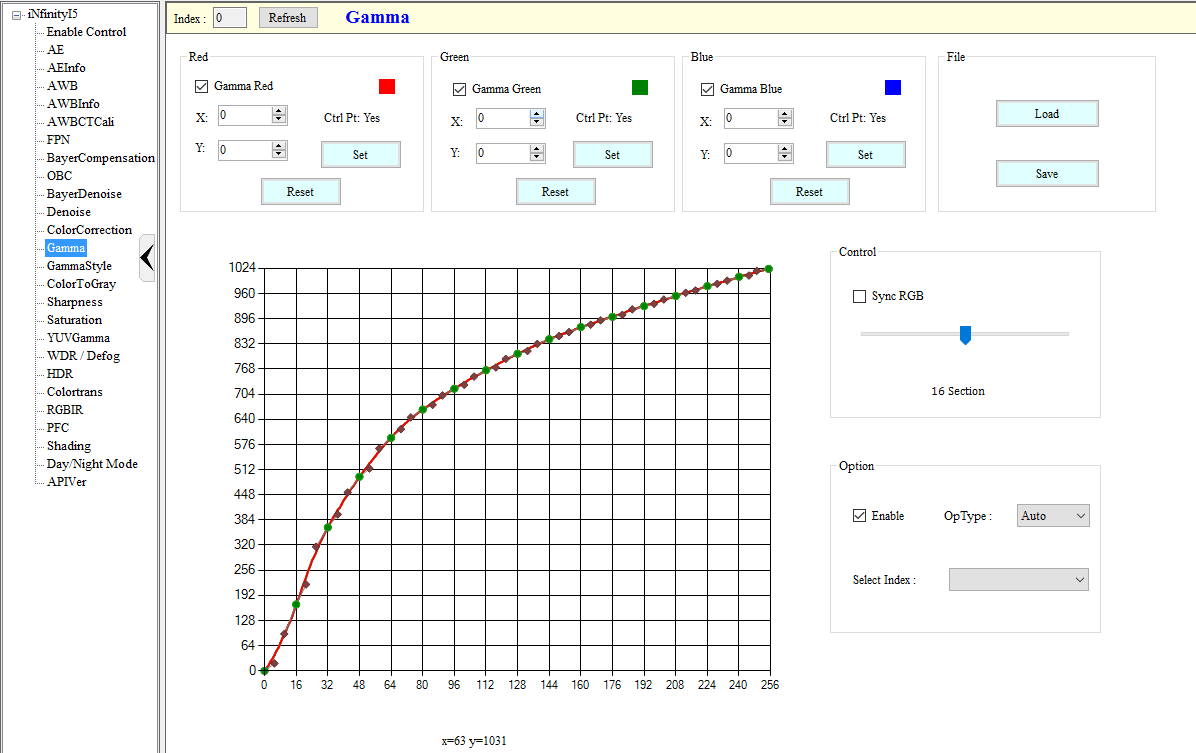
-
For a quick overview of functions in Gamma tuning interface, please refer to the following figure.
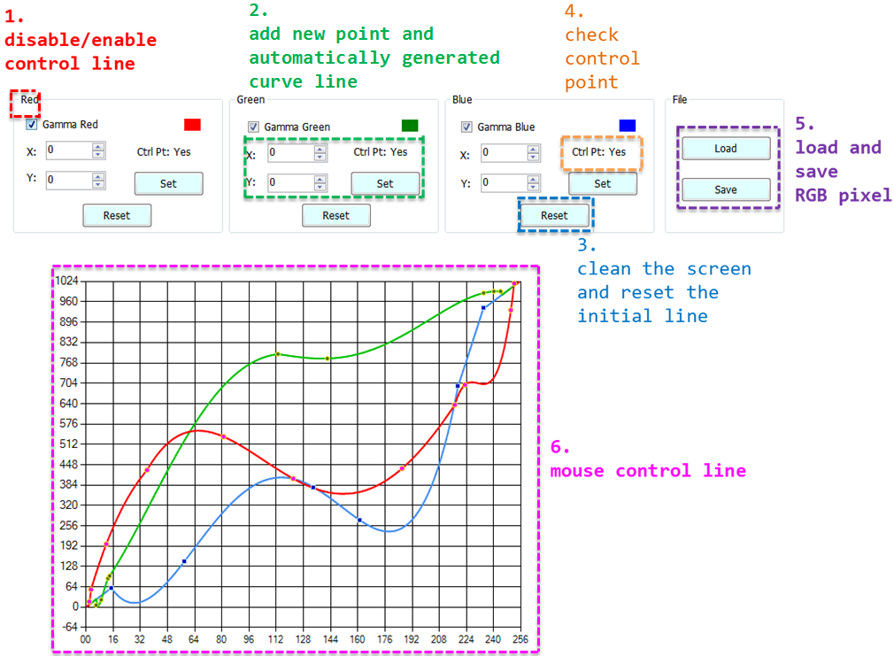
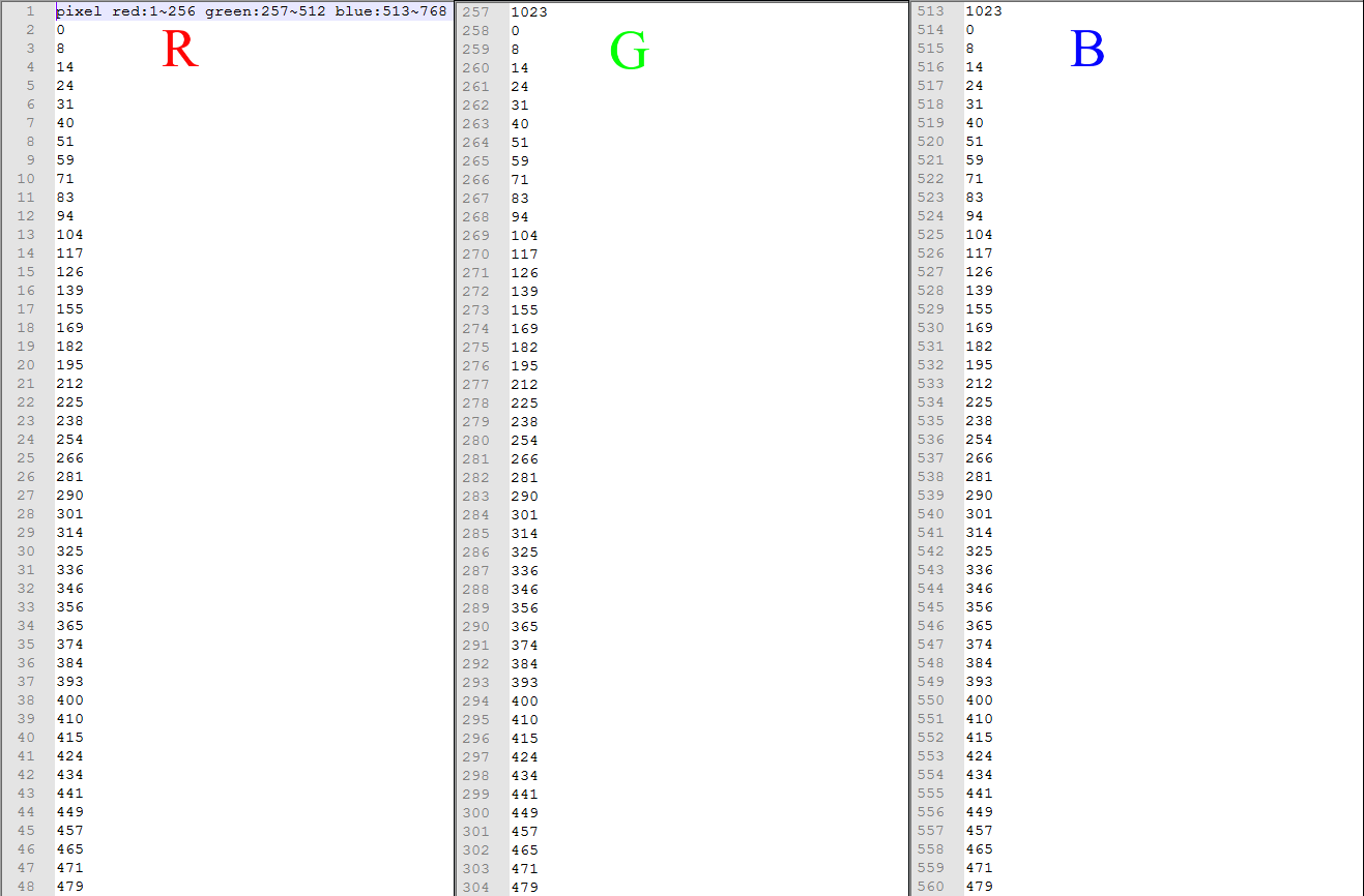
-
For a detailed description of Gamma tuning functions, please refer to Table 2.
Table 2: Detailed Descriptions of Gamma Tuning Function
Num Gamma Interface Function Icon Function Description 1 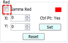
Disables/Enables control over R,G,B line - If Gamma Red is checked, the red line will be controllable by the mouse and is visible.
- If Gamma Red is not checked, the red line will not be controllable by the mouse and is not visible.
- The same applies to Gamma Green and Gamma Blue.2 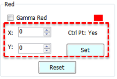
Creates new point and automatically generates curve line Move the up/down arrow to adjust the values on X-axis and Y-axis (or input the desired values in the fields), and click “Set”
- If there is no control point yet, new (x,y) control points will be added to the curve line and form a smooth curve based on new control points.
- If a control point already exists on the X-axis of the curve line, the new value on Y-axis will be taken as the control point and form a smooth curve.3 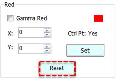
Resets the initial line Clear R, G or B lines, and restore the initial setting (bypass gamma). 4 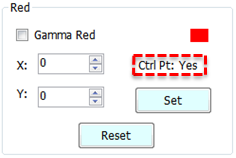
Checks the control point “Yes” if a control point has been successfully created, “No” otherwise. 5 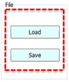
Loads and saves RGB pixel - Load: Load the txt file bearing RGB pixel values, and an RGB curve line will be generated automatically.
- Save: Save the RGB curve line pixel values as a txt file.
- The file format is: R→G→B; Header: 0 (description); Pixel red: 1 ~ 256; Pixel green: 257 ~ 512; Pixel blue: 513 ~ 768.6 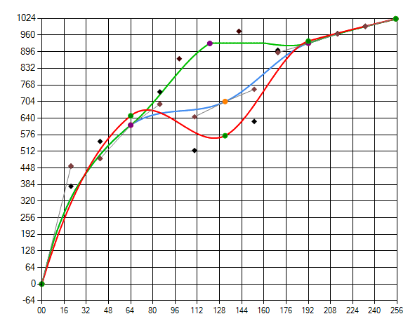
Mouse control page - Left click the curve to add a new control point. Move the control point and the auxiliary point to create a smooth curve.
- Right click the control point to delete it.7 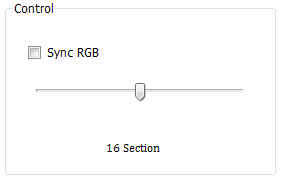
Control point option - If Sync RGB is checked, the R, G and B curve lines will merge into one gray line. Modifying this gray line will modify the R, G and B lines at the same time.
- Drag the Section Bar leftward/rightward to set the number of control points for the curve line. -
To adjust Gamma curve: The R, G and B curves are shown on the coordinates when initialized. By checking Gamma Red, Gamma Green and Gamma Blue, you can move the cross symbol to control the curves by mouse. If you happen to click the spot where the three curves overlap, the priority will be Red, Green and then Blue. Let’s take R curve as an example. You can left click the mouse to add a new control point and right click to delete it. Moving the control point can modify the curve. Two auxiliary points are provided along the control point, to help fine tune the Bezier curve. There are 256 pixel values each for R, G and B. See the following figure for details.
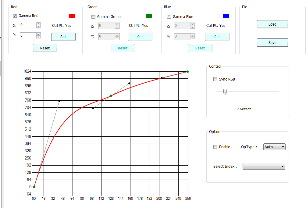
-
Read Page and Write Page of Gamma Curve:
-
Read Page: This enables you to get API. Click “Read Page” and you will get the values from the curve that is currently effective.
-
Write Page: This enables you to set API and write the curve value from the current UI to the platform. In the case of Gamma, you must click “Write Page” manually to write data. For all other APIs, auto write is enabled. Please refer to the following figure for Read Page and Write Page buttons.
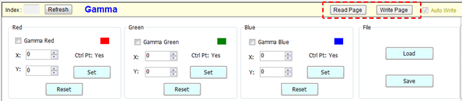
-
Shading
Adjustment Interface
Select “Shading” from the menu on the left-hand side to call out ALSC Interface.
If you want to turn off this IP, go to the Enable Control page and click Disable.
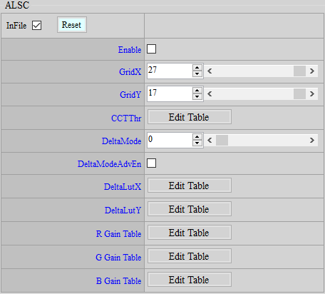
Parameter Description
Enable: Enable ALSC API function. 0 means disable, and 1 enable. Parameter range: 0 ~ 1.
GridX: The size of shading table in the direction of X. The default size on this platform is 27. Parameter range: 1 ~ 27.
GridY: The size of shading table in the direction of Y. The default size on this platform is 27. Parameter range: 1 ~ 27.
CCTThr: Set the node of ambient color temperature. Up to three shading calibration tables are supported. Note: You should fill in the index from small to large by following the order from low to high color temperature. Parameter range: 1 ~ 3.
DeltaMode: There are 16 modes by default. The vertical axis represents each mode, while the horizontal axis represents the size of each grid in X/Y direction. On this platform, the preset spacing is 26-grid in X direction and 16-grid in Y direction. The greater the value in the preset mode, the smaller the grid. Parameter range: 0 ~ 15.
DeltaModeAdvEn: Enable advanced mode. 0 means disable, and 1 enable. Parameter range: 0 ~ 1. When GridX/Y is of a size other than the default 27×17 set for this platform, you must enter this mode to adjust non-uniform grid settings.
DeltaLutX: Spacing on the X-axis. Each index value represents a block size (index = block size / 16). The index value is limited to 1, 2, 4, 8, and 16. If no block is used, set it to 0. Up to 72 sets of blocks are supported. In this platform, the spacing is 26-grid.
DeltaLutY: Spacing on the Y-axis. Each index value represents a block size (index = block size / 16). The index value is limited to 1, 2, 4, 8, and 16. If no block is used, set it to 0. Up to 72 sets of blocks are supported. In this platform, the spacing is 16-grid.
R/G/B Gain Table: Click any of the R/G/B Gain Table to generate a new interface, in which the screen will be divided into a 27x17 matrix. The value in each box represents the weight by which the R/G/B component at this position needs to be multiplied. Parameter range: 0 ~ 4095.
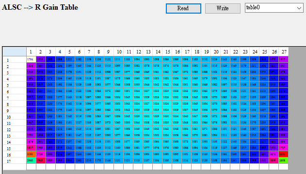
-
<Auto ALSC Table Adjustment API>
The spectra of light sources with similar color temperatures are not necessarily the same (so-called metamerism). For some lens modules, different color shading performances will be achieved under light sources with metamerism and metamerism. For such lens modules, a set of shading The table cannot obtain good compensation results under the light source with different colors. For this reason, the adaptive algorithm can automatically determine whether there is color shading in the picture, and reduce the color shading by fine-tuning the shading table in the current ALSC table. It is recommended to enable this function when the compensation is not good under the light source with the same color but different spectrum after completing ALSC compensation for high/medium/low color temperature.
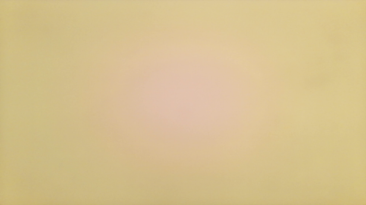

The adjustment interface is as follows:
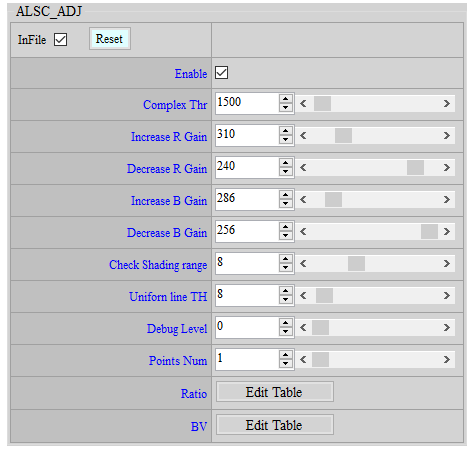
Parameter introduction:
Complex Thr: The value range is 0 ~ 65536. If the complexity of the area within the search range is less than Complex Thr, it will be included in the candidate area for color shading evaluation.
Max Increase R Gain: The value range is 256 ~ 512, which allows the algorithm to increase the maximum amount of R in the ALSC table, 256 is 1 times.
Max Decrease R Gain: The value range is 128 ~ 256, which allows the algorithm to reduce R in the ALSC table by the minimum amount, 256 is 1 times.
Max Increase B Gain: The value range is 256 ~ 512, which allows the algorithm to increase the maximum amount of B in the ALSC table, 256 is 1 times.
Max Decrease B Gain: The value range is 128 ~ 256, which allows the algorithm to reduce the minimum amount of B in the ALSC table, 256 is 1 times.
Note: It is recommended that the above four parameters Increase/Decrease R/B Gain be adjusted to appropriate values in the light box. It is not recommended to set them too large or too small to avoid color cast when the algorithm misjudges the image.
Check Shading Range: The value range is 8 ~ 16. The screen is divided into 32 areas in the horizontal and vertical directions. This value represents the range of search from the center of the screen. It is recommended to set it to the area where the lens module has obvious color shading. The adaptive algorithm determines whether to compensate based on the shading performance within the total check range. If the range is set too large, it may include too many areas without obvious shading, affecting the overall evaluation results.
Uniform line TH: The value range is 8 ~ 128. The shading evaluation of the picture will be performed only when the candidate area in the picture (< Complex Thr) is larger than the uniform line count TH. If the algorithm is prone to misjudgment in general scenes, it is recommended to increase this parameter and perform calculations only when there are enough candidate areas.
Ratio By BV: In low light scenes, the compensation amount can be reduced according to BV. This parameter will directly affect the Increase/Decrease R/B Gain within the algorithm.
Adjustment flow:
-
First, perform ALSC calibration with 2~3 different color temperatures in the light box. After the calibration is completed, switch to a light source with the same color but different spectra, and observe the area where color shading appears to set the Check Shading Range.
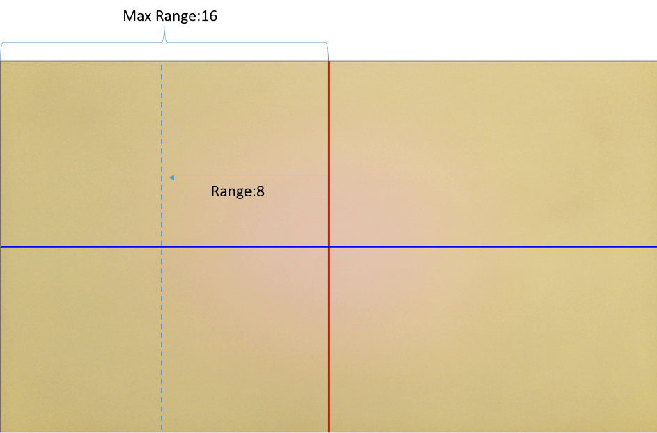
-
After determining the shading area, set the Debug Level to 1. Uart will print the area number that is less than Complex Thr in the screen, as well as the R complexity and B complexity of the area. The area number corresponds to the position of the screen. At this time, Complex Thr can be gradually increased to ensure that all areas with color shading in the light box environment can be included in the shading evaluation. Note that the number of printed counters must be greater than the Complex Scene counter for the scene to be included in the calculation.
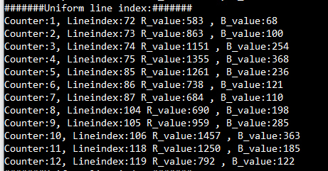
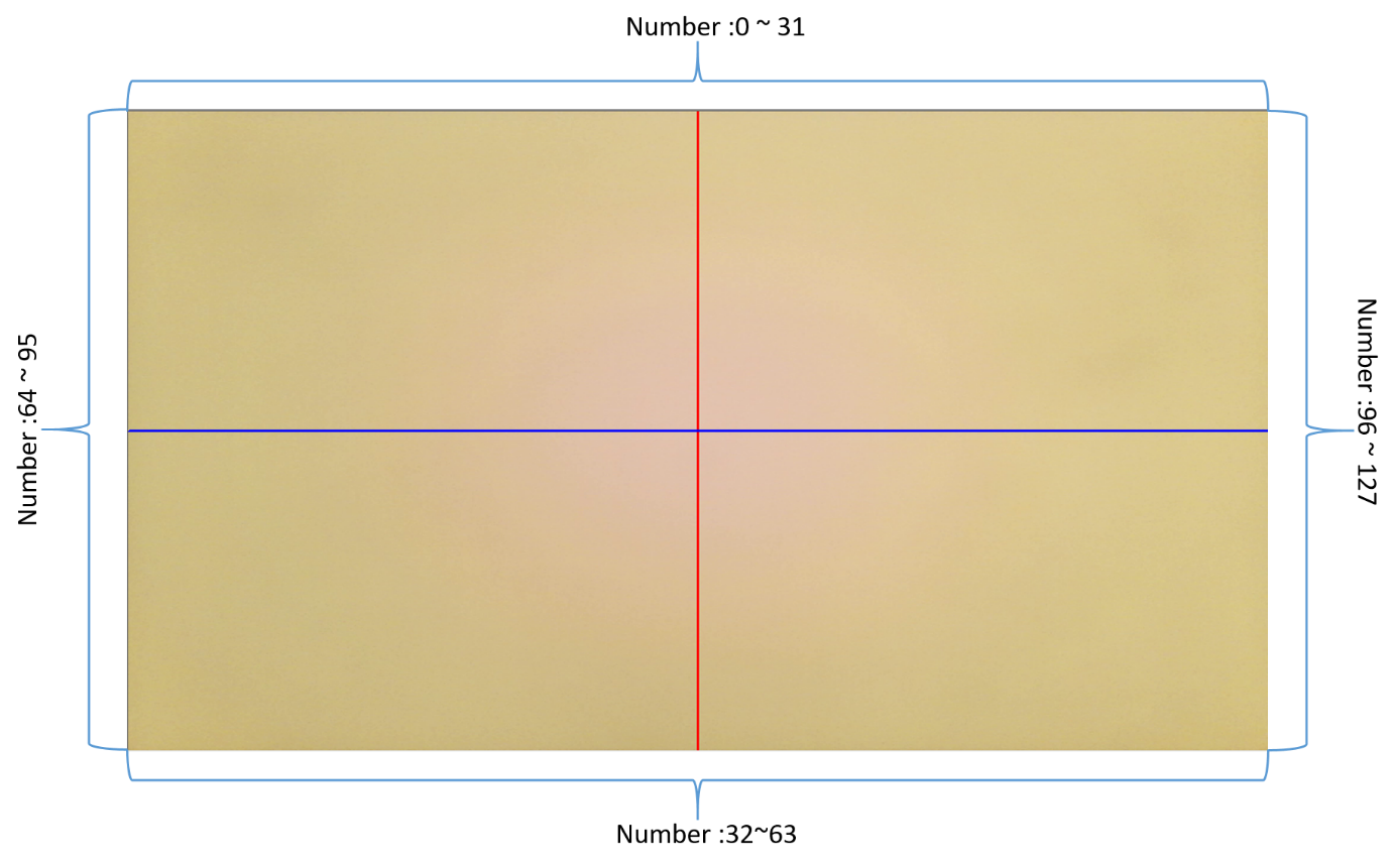
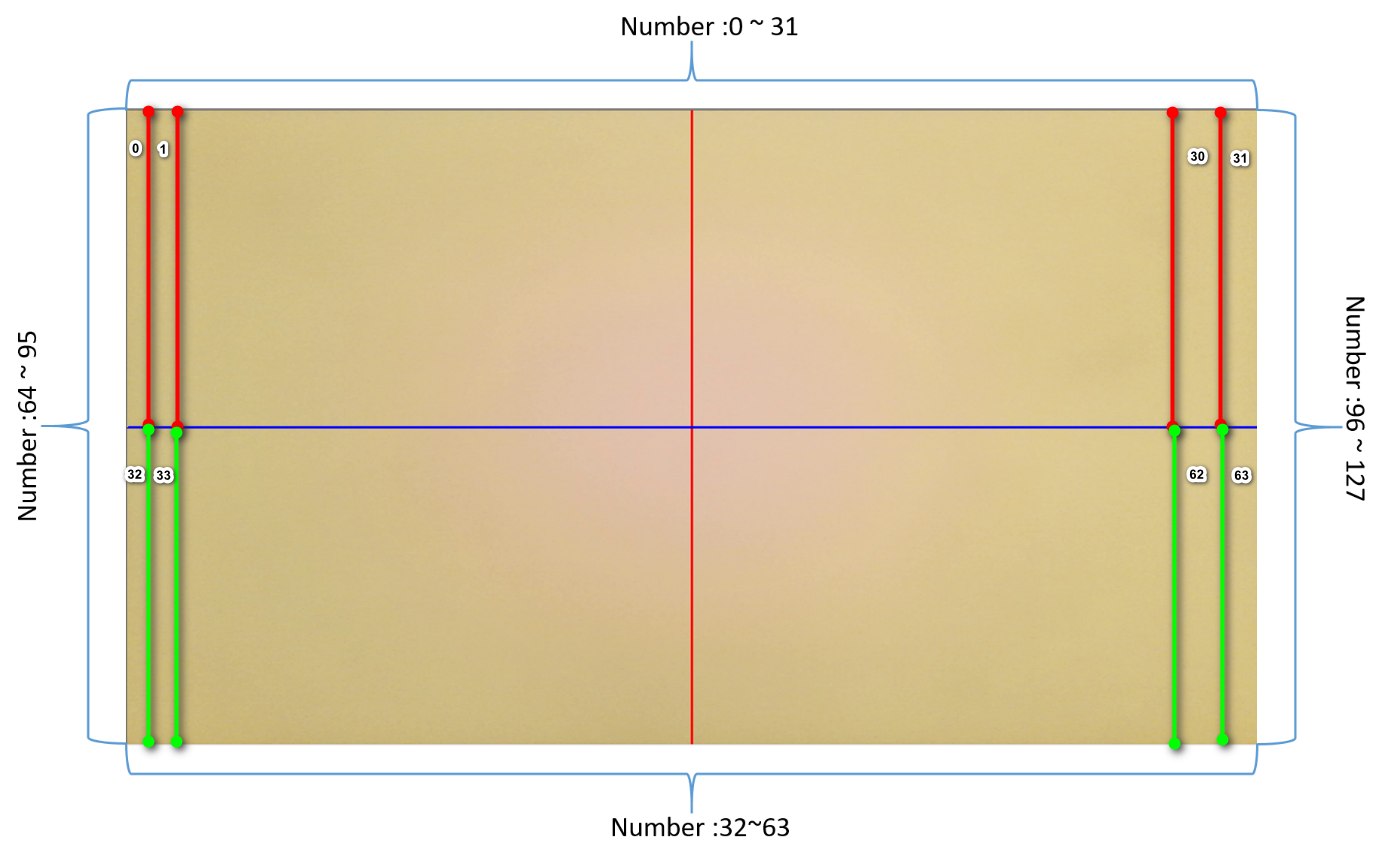
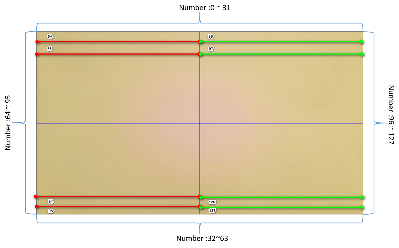
-
After determining the Complex Thr, set the Debug Level to 2. At this time, UART will print out the overall shading judgment result of the picture and the compensation amount of R and B gain. If the middle of the picture is red and the sides are green, the R_ratio will be less than 256. You need to gradually increase Max Increase RGain, allowing the algorithm to pull up the R component, and adjust Max Increase RGain until R_ratio = 256. Do the same for the B component, and vice versa. The following figure shows the actual compensation log.
-
Max Increase/Decrease RGain/BGain can be fine-tuned according to different color temperature conditions. Fine-tune to the appropriate gain. Setting it too large or too small may cause the color of the picture to be biased when shading is misjudged.
-
In order to save computing power, Debug Level = 2 will display the current algorithm status. The following is a description of each status:
SHADING_CHK: Checks whether the current image meets the conditions for shading compensation, and performs shading detection and adjustment.
NO_IMPROVE_PAUSE: After several rounds of compensation, R_ratio and B_ratio cannot reach 256. The algorithm will stop checking and maintain the current compensation amount. This state means that after the algorithm adjusts the ALSC table, it still cannot reach ratio 256, or the compensation gain has reached the set maximum.
COMPLEX_PAUSE: The current screen does not meet the conditions for compensation (uniform line counter > uniform line count TH), so compensation stops.
STABLE_PAUSE: After several rounds of compensation, R_ratio and B_ratio reach 256, and the calculation is paused to maintain the current compensation amount.
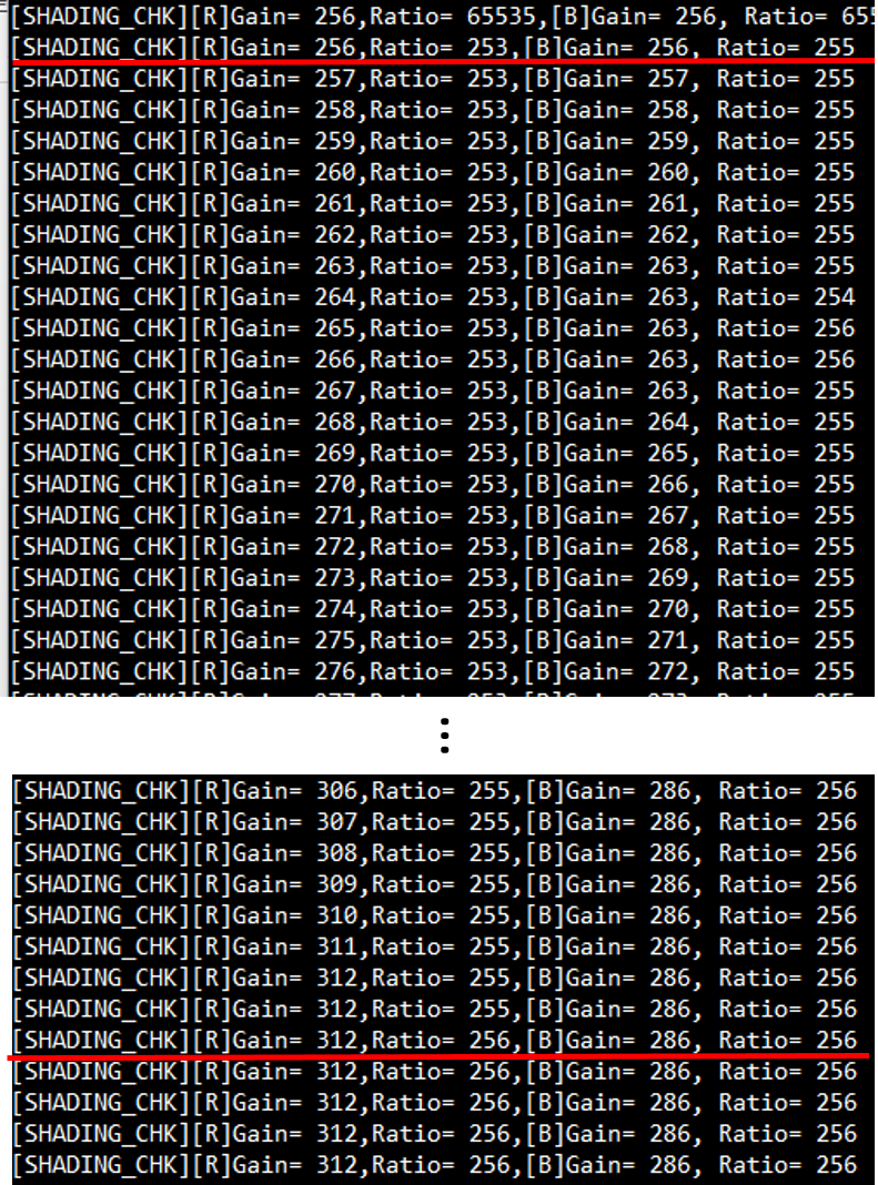
-
Plugin
IQ Tool provides five plug-ins: AF, AWB, CCM, GAMMA, and ALSC to assist IQ debugging, as the following figure shows:
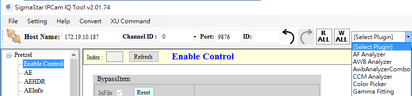
AF Analyzer
AF Analyzer is an autofocus correction analysis plug-in that mainly uses frequency response values to convert filter coefficients.
Adjustment interface
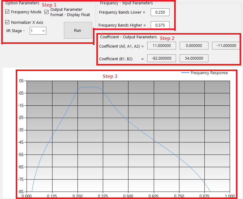
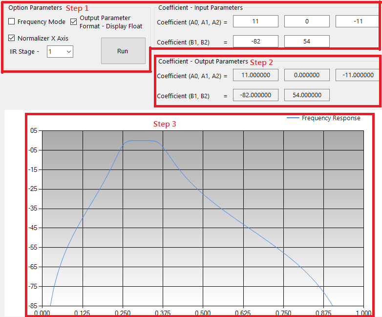
Parameter Description
-
Step
-
Enter AF parameters
Frequency Mode: Input cutoff frequency to generate frequency response
NonFrequency Mode: Input AF Filter coefficient to generate frequency response
-
Output AF Filter coefficient
-
Output AF frequency response curve
-
-
Input parameters
-
Bands lower: The minimum value of low-frequency response, the value range is 0.001 ~ 1.000.
-
Bands higher: The maximum value of high-frequency response, the value range is 0.001 ~ 1.000.
-
Display float option: enable → display AF coefficient, disable → display AF coefficient (two's complement).
-
Normalizer X options: enable → normalizes the X-axis value range, disable → does not normalize the X-axis value range.
-
Run button: Calculate Coefficient A0, A1, A2, B1, B2 and draw AF frequency response curve.
-
Frequency Mode option: Select the input parameter method.
-
Coefficient: Enter the AF Filter coefficients of each level in NonFrequency Mode.
-
IIR Stage: Select the AF Filter level.
Frequency Mode: Just enter the cutoff frequency directly.
NonFrequency Mode: Input coefficients according to the number of stages. For example, select 1 for the first stage AF Filter and input the coefficients for Coefficient. For the second stage AF Filter, select 2 and input the coefficients for Coefficient again. etc.
-
-
Output parameters
- AF Filter Coefficient: A0, A1, A2, B1, B2
-
Frequency response curve
-
X-axis: number of sampling points
-
Y axis: frequency value (db)
-
AWB Analyzer Combo
Awb Analyzer Combo is a white balance correction analysis plug-in, which mainly includes two parts, Statistics Analyzer and Raw Analyzer. Statistics Analyzer allows users to adjust the color temperature curve range, while Raw Analyzer mainly allows users to understand the Awb statistical value of each position in the picture.
Adjustment interface
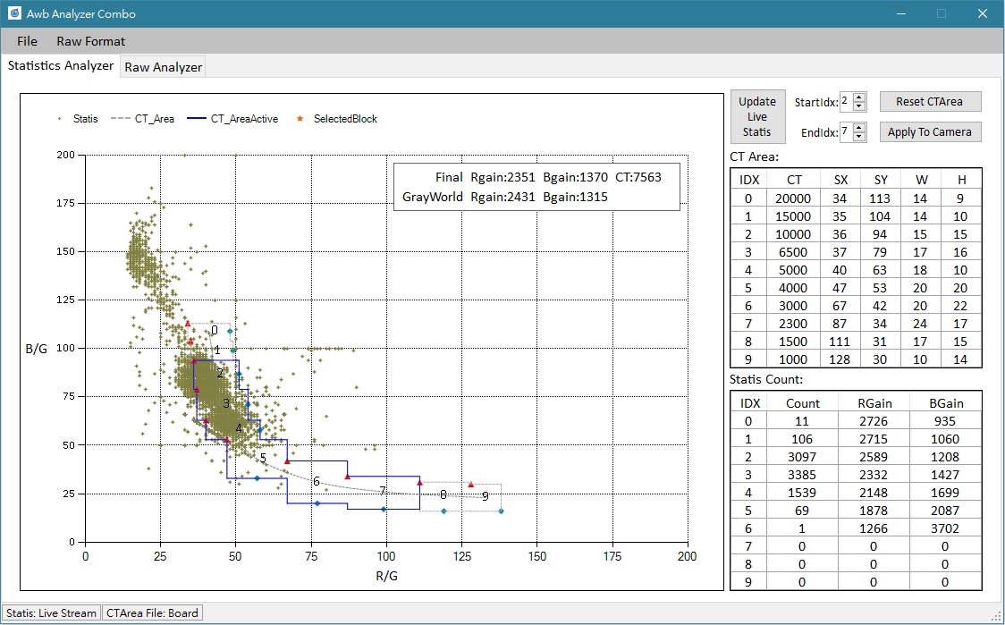
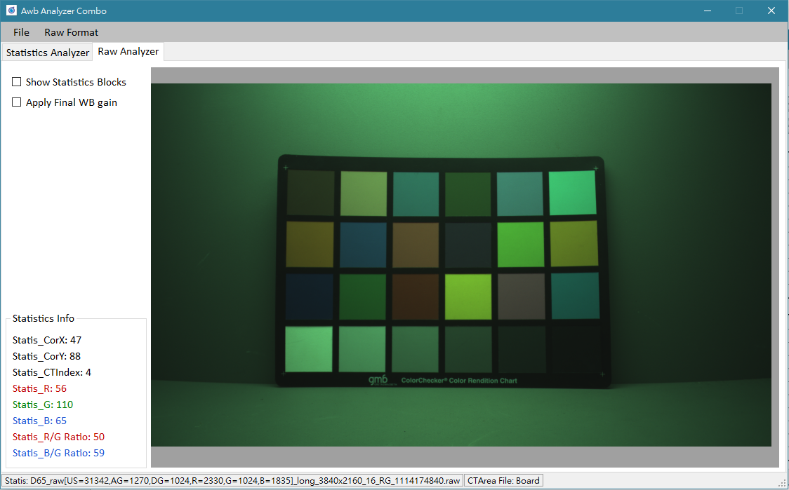
Usage and Parameter description
-
Click function selection:
Click the function label at the top of the interface to switch.
-
Statistics source settings:
Click File->Load Statistics in the menu bar at the top of the interface and three source options will appear.
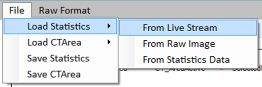
From Live Stream: Get the statistics of the current stream. IQTool needs to be connected to the Internet before using this function. If you want to update the statistics, select the Update Live Statistics button in the upper right corner.
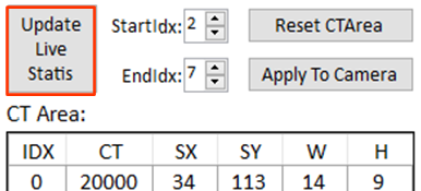
From Raw Image: Get statistics from the raw image. Before selecting this option, please set the raw image format through Raw Format in the menu bar (For the Image Decompress setting method, please refer to Raw Setting Parameter Description).
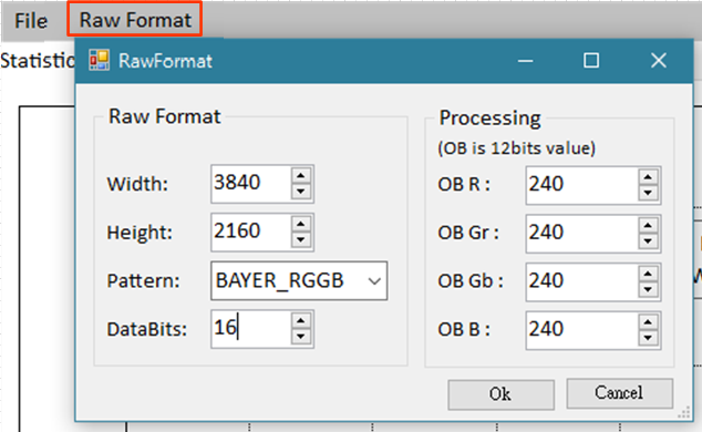
From Statistics Data: Get from previously saved statistical value files.
-
Color temperature curve range source setting:
Click File->Load CTArea in the menu bar at the top of the interface and two source options will appear.
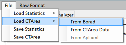
From Board: Get from the connected machine. IQTool needs to be connected before using this function.
From CTArea Data: Get from the previously saved color temperature curve range file.
-
Save statistics: Click File->Save Statistics in the menu bar at the top of the interface.
-
Save the color temperature curve range: Click File->Save CTArea in the menu bar at the top of the interface.
-
Adjust the color temperature curve range: directly drag the position control point (triangle) and range control point (diamond) on the color temperature box.
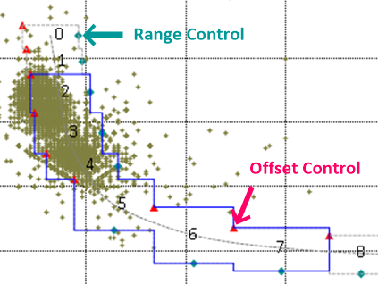
-
Reset color temperature curve range: Click the Reset CTArea button in the upper right corner.
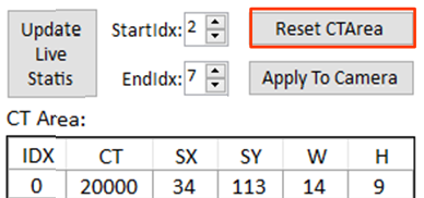
-
Effective color temperature curve range Index: Set through StartIdx and EndIdx in the upper right corner. Only the statistical values that fall within this range of color temperature boxes will be taken into calculation.
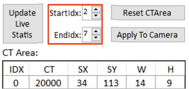
-
Apply the color temperature curve range: Select the Apply To Camera button in the upper right corner.
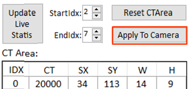
After applying, remember to return to the IQTool interface and select the AWBCTCali project to perform the Read Page action (Do not click Write Page before clicking Read Page), so that the adjusted color temperature curve range can be saved when the API bin file is stored.
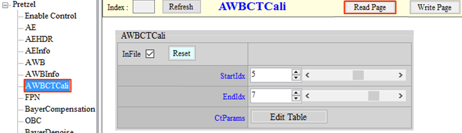
-
Move & zoom to display raw image; hold down the left mouse button to drag the image, and scroll the mouse wheel to zoom in or out.
-
Show Statistics Blocks: Select Show Statistics Blocks to display the statistics blocks on the screen.
-
Select the statistical value block: Double-click the left mouse button to select the block, and the left information bar will display the block information. In addition, the location of the block will be shown in the color temperature coordinates (star shape). Click the right mouse button to deselect.
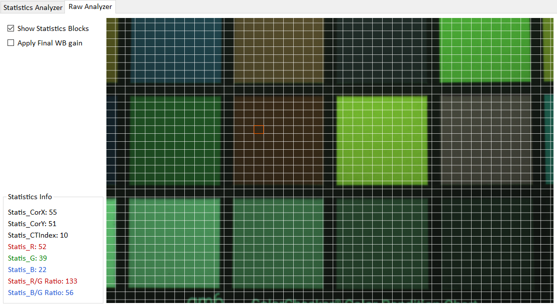
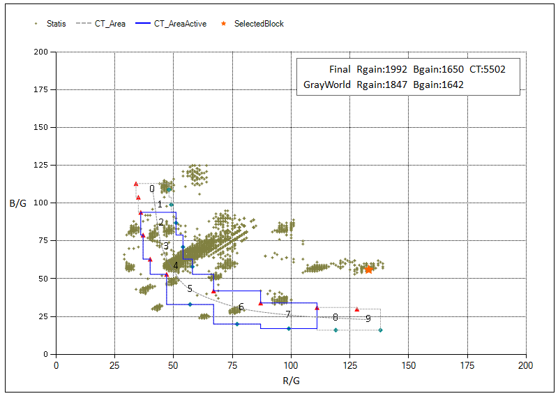
-
Display the image of applying Final RBgain: Select Apply Final WB gain.
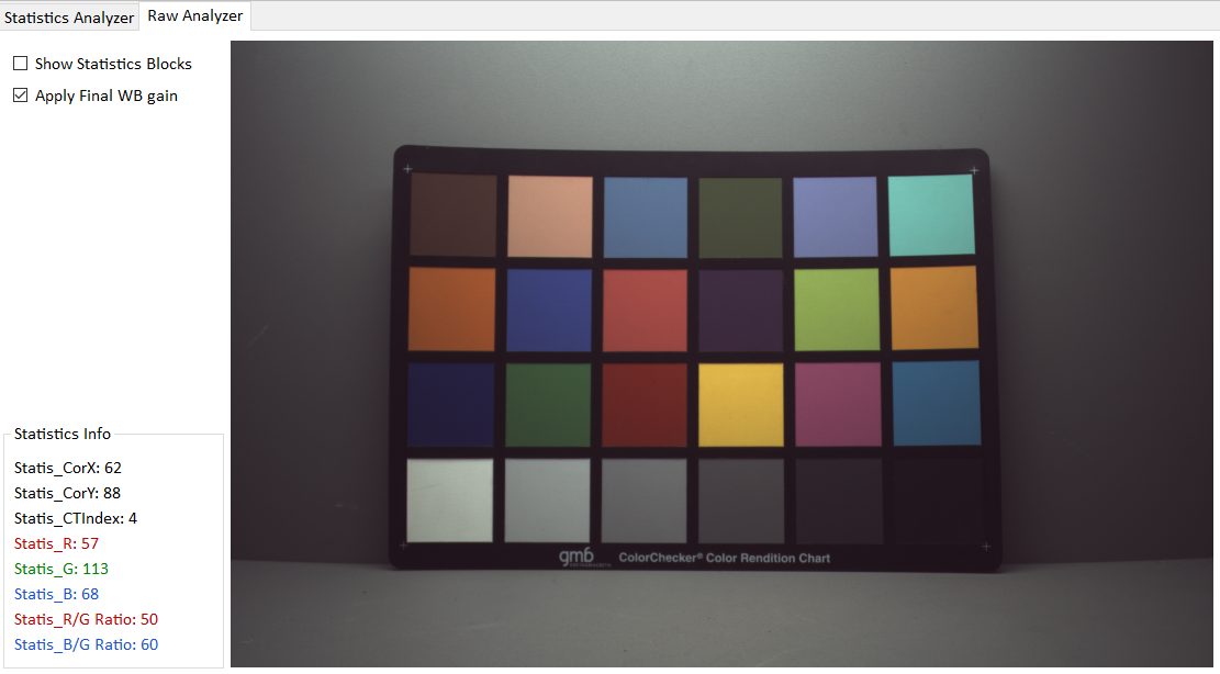
CCM Analyzer
This plugin tool is used for color correction.
Adjustment interface
The Calculate CCM page is used for CCM calibration. When it is started, it will read the relevant reference values from the Camera, so it cannot be debugged offline. FineTuneMatrix is a fine-tuning function.
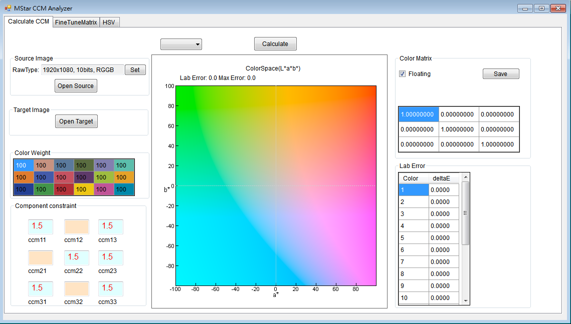
Usage and Parameter description
-
How to use
Click Set in Source Image to set the Raw Data information (for the Image Decompress setting method, please refer to Raw Setting Parameter Description). Click open source to open the saved raw image. After opening, a window will appear showing all the information. Select the raw image and drag it directly on the screen with the mouse so that each color block is correctly selected. After completion, click OK, Open Target to open the standard color checker picture, and follow the above steps to select the color checker.
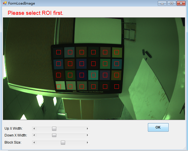
-
Parameter settings
-
Target Image:
Users can choose Default Target, and Xrite after 2014 / Xrite before 2014 / BabelColor Avg is available.
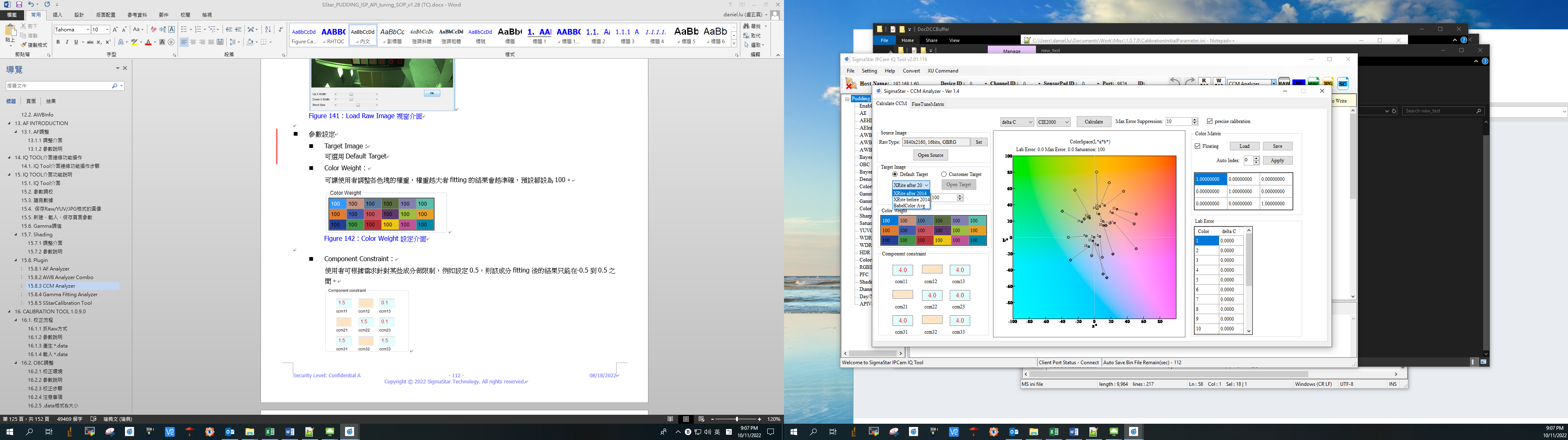
Users can also customize Target and import it from bmp or txt.
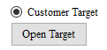
Target Saturation allows users to set the final saturation of the correction, the default setting is 100 (it is recommended not to be changed).
-
Color Weight:
Allows users to adjust the weight of each color block. The larger the weight, the more accurate the fitting result will be. The default setting is 100.
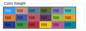
-
Component Constraint:
Users can set limits on certain components according to their needs. For example, if you set it to 0.5, the result of fitting for this component can only be between -0.5 and 0.5.
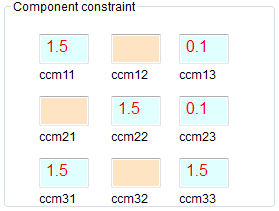
-
Max Error Suppression:
Users can set Max Error suppression according to their needs. The value range is 0 ~ 100. The larger the value, the stronger the Max Error suppression effect, but the Avg Error will increase. It is recommended to set it below 50.
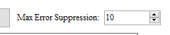
-
After the settings are completed, select the calculate button and the final fit result will be displayed on the right side of the window.
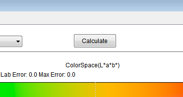
-
Repeat the above steps to fit the color matrix of the remaining color temperatures.
-
Gamma Fitting Analyzer
This plug-in tool is used for Gamma Fitting correction.
Adjustment interface
CDF_Orig: CDF curve of open source.
CDF_Ref : CDF curve of open target.
FitGMA: Fitting Gamma curve.
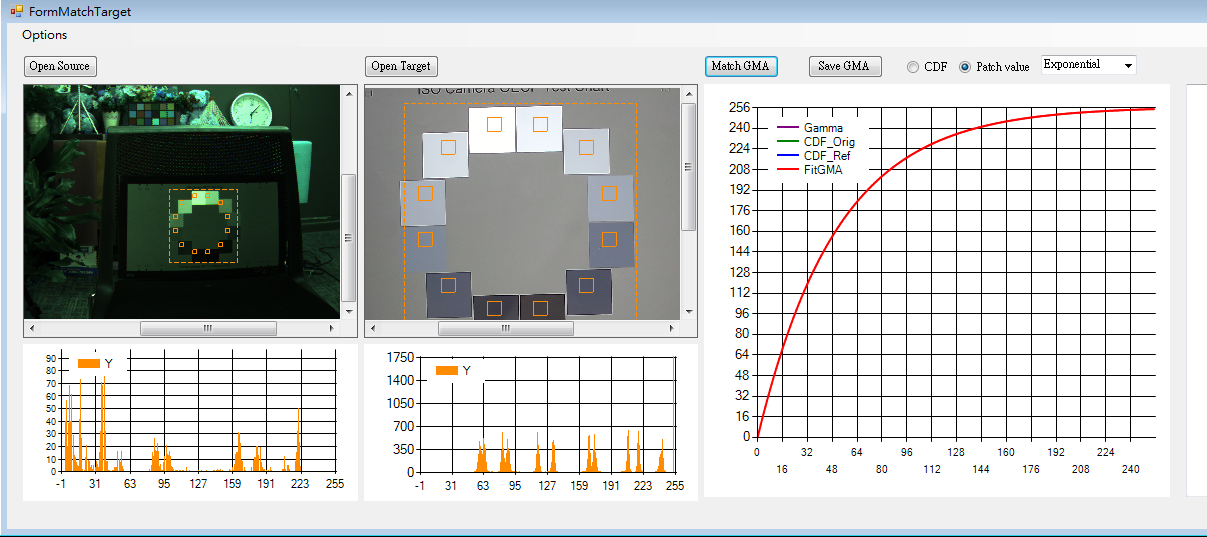
Usage and Parameter description
-
How to use
-
Read the gamma curve of the image and click the Raw Setting initial setting in Options (for the Image Decompress setting method, please refer to Raw Setting parameter description).
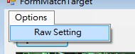
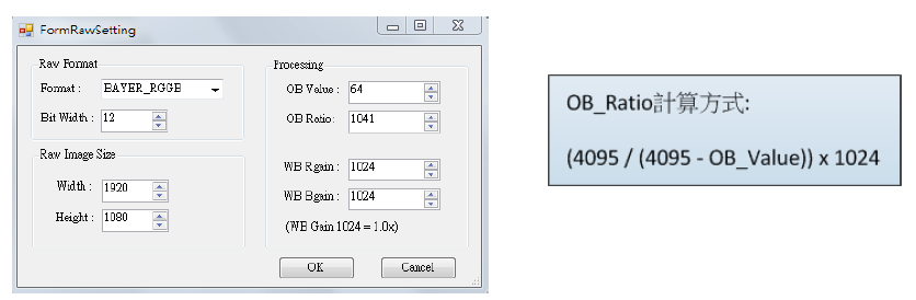
-
Click open source to open the saved raw image
-
Click open target to open the standard OECF Chart image
-
Press the left button to select ROI and automatically generate the corresponding histogram
-
Select the Gamma curve type. There are two curve calculation methods. It is recommended to select Exponential
-
Spline curve
-
Exponential Curve
-
-
Click the Match GMA button to generate the Gamma curve
-
Click the Save GMA button to save the calculated Gamma parameter value.
-
SStarCalibration Tool
This plug-in tool is used for shading and black level correction. Its function is the same as the calibration tool.
CalibrationALSC Adjustment Interface
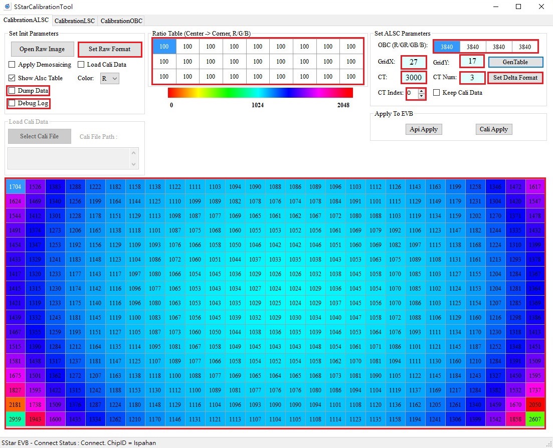
CalibrationALSC Usage and Parameter description
-
Parameter settings
-
Ratio Table: Correction intensity ratio from the center of the screen to the corners, value range 0 ~ 255.
It allows the user to adjust the weight of each color block. The larger the weight, the more accurate the fitting result will be. The default is set to 100.
-
OBC: The current OB value of the sensor, the unit is 16-bit, the value range is 0 ~ 65535.
-
GridX, GridY: The size of the shading table.
-
Set Delta Format: Non-equidistant grid setting.
-
Delta Mode: There are 16 preset modes, ranging from 0 to 15. For the setting method, please refer to "Delta_LUT_X default 16 modes distribution" and "Delta_LUT_Y preset 16 modes distribution".
-
Delta Mode Advance Enable: Select to enable the advanced mode switch, 0 means off, 1 means on, the value range is 0 ~ 1. When GridX/Y uses non-preset 27x17, you must enter this mode to set non-equidistant grids.
-
Delta X Lut : X-axis spacing. The actual number of pixels is this value multiplied by 16. Only 1, 2, 4, 8, and 16 are allowed. If not used, fill in 0.
-
Delat Y Lut: Y-axis spacing. The actual number of pixels is this value multiplied by 16. Only 1, 2, 4, 8, and 16 are allowed. If not used, fill in 0.
-
-
CT: Color temperature, value range is 1 ~ 20000.
-
CT Num: Select the number of color temperature table data to be calibrated. The default is to calibrate 3 sets of color temperature tables, value range is 1 ~ 3.
-
CT Index: Select the table group to be calibrated. Up to 3 groups are supported. The calibration sequence does not need to follow the order from 0 to 2, but it is necessary to ensure that the ambient color temperatures from 0 to 2 are from low to high and cannot be the same.
-
Open Raw Image: Select the Raw image path.
-
Set Raw Format: Set Raw image related parameters.
-
Apply Demosaicing: Apply simple Demosaic to the Raw image.
-
Show Alsc Table: Displays the shading table.
-
Color: Displays the R/G/B gain of the shading table.
-
GenTable: Generates a shading table based on the input parameters.
-
ApiApply: Only the current CT Index shading table will be downloaded to the API.
-
CaliApply: transfer all parameters to the board at once according to the current CTNum size.
-
Debug Log: You can see the debug log during GenTable and Apply.
-
Keep Cali Data: Load the generated .data data so that the previous results can be retained and continued to be calibrated.
-
Dump Data: txt file that generates correction results.
-
Load Cali Data: Load the generated .data so that it can use CaliApply to apply the correction result of that .data.
-
Select Cali File: Only when Load Cali Data is checked, it can be clicked to select the .data to be applied to the board.
-
-
How to use
There are two routes depending on whether Load Cali Data is checked or not.
Checked:
-
After checking Load Cali Data, click Select Cali Data and select the .data you want to apply.
-
After selecting the .data you want, you can only use CaliApply. At this time, the calibration parameters of Apply will not be displayed on our SStarCalibrationTool.
Unchecked:
-
Click Set Raw Format to set the raw image information, and click Open Raw Image to open the raw image. You can check Apply Demosaicing to view the RGB image. This is just a simple demosaicing function, which is different from the actual one. Whenever you uncheck Load Cali Data, you must click Open Raw Image again to open the raw image.
-
Set the parameters for generating the shading table, including Ratio Table, OBC, GridX, GridY, Set Delta Format, and then click GenTable to generate the shading table. You can check Show Alsc Table to view the shading table. When you have calibrated the first set of parameters, if you want to keep the results and continue calibrating, you can check Keep Cali Data. However, if the size of CT Num is changed when calibrating the second set of parameters, the Keep Cali Data function will be lost.
-
Set the parameters of the board, including CT and CT Index, and then click ApiApply or CaliApply to take effect. Please be sure to go to the ALSC interface and click Read to see the same parameters as CalibrationALSC. Every time Apply is completed, GenTable, CaliApply and ApiApply will be turned gray. At this time, if there are any changes in the settings in the red frame in the above picture, you can recalibrate them again.
-
CalibrationLSC Adjustment Interface
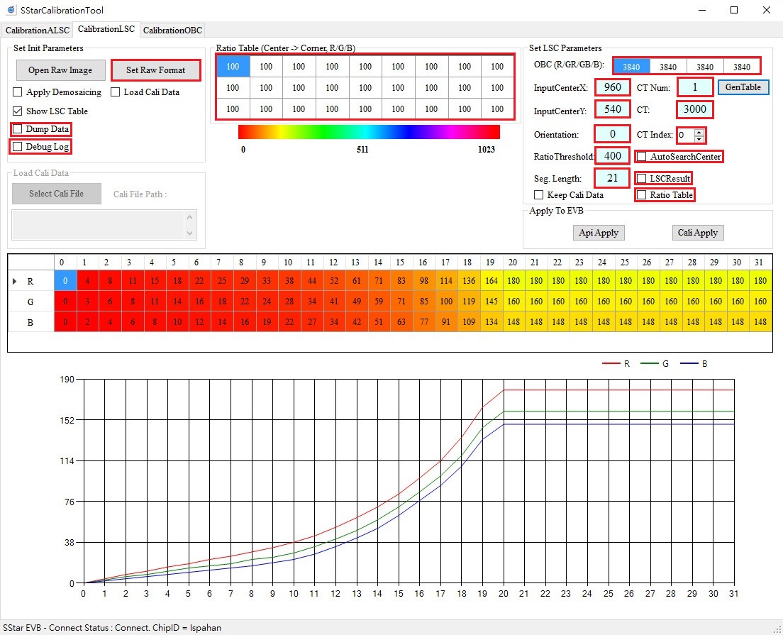
CalibrationLSC Usage and Parameter description
-
Parameter settings
Ratio Table: Correction intensity ratio from the center of the screen to the corners, value range 0 ~ 255.
Allows the user to adjust the weight of each color block. The greater the weight, the more accurate the fitting result will be. The default is 100.
OBC: The current OB value of the sensor, unit 16-bit, value range 0 ~ 65535.
InputCenterX, InputCenterY: Set the brightest center point of the image, value range: 0~4095.
CT: Color temperature, value range is 1 ~ 20000.
CT Num: Select the table group to be calibrated. A maximum of 3 groups are supported. The calibration sequence does not need to follow the order from 0 to 2, but it is necessary to ensure that the ambient color temperatures from 0 to 2 are from low to high and cannot be the same.
CT Index: Supports up to 3 groups of color temperatures, with a value range of 0 to 2, and will be linked according to the size of CTNum.
Open Raw Image : Select the Raw image path.
Set Raw Format: Set Raw image related parameters.
Apply Demosaicing: Apply simple Demosaic to the Raw image.
Show LSC Table: Displays the shading table.
GenTable: Generates a shading table based on the input parameters.
ApiApply: Only the current CT Index shading table will be downloaded to the API.
CaliApply: Transfer all parameters to the board at once based on the current size of CTNum.
Debug: Log: You can see the debug log in GenTable and Apply.
Keep Cali Data: Load the generated .data data so that the previous results can be retained and continued to be calibrated.
Dump Data: txt file that generates calibration results.
Load Cali Data: Load the generated .data so that it can use CaliApply to apply the correction result of that .data.
Select Cali File: Only when Load Cali Data is checked, it can be clicked to select the .data to be applied to the board.
Orientation: Set the direction of the sampling point, from the brightest center point of the image to the corner point. 0: upper-left, 1: upper-right, 2: lower-right, 3: lower-left
Seg. Length: The length distance of cutting sampling points.
AutoSearchCenter: Select to automatically detect the brightest center point position of the input image. The value range is 0 ~ 1. It is recommended to set it to 1.
LSCResult: Dump LSC result image.
Ratio Table: Whether to use the compensation value of the Ratio Table for correction. When this is checked, the Ratio Table can be changed.
RatioThreshold: Used to prevent over-compensation of vignetting compensation. The larger the value, the more vignetting compensation, and the smaller the value, the less compensation. The more vignetting compensation, it will cause normal data close to the corners to be over-compensated. When the threshold is smaller, the compensation value will be found based on the current maximum index value and set to the maximum value, and the index value after the maximum index value will maintain the maximum compensation value (without increasing the value); otherwise, the larger the threshold, the compensation value will be set to the maximum value. The larger the value, Ratio Base = 100, the value range is 0 ~ 25600.
-
How to use
There are two routes depending on whether Load Cali Data is checked or not.
Checked:
-
After checking Load Cali Data, click Select Cali Data and select the .data you want to apply.
-
After selecting the desired .data, you can only use CaliApply. At this time, the calibration parameters of Apply will not be displayed on our SStarCalibrationTool.
Unchecked:
-
Click Set Raw Format to set the raw image information, and click Open Raw Image to open the raw image. You can check Apply Demosaicing to view the RGB image. This is just a simple demosaic function, which is different from the actual one. Whenever you uncheck Load Cali Data, you must click Open Raw Image again to open the raw image.
-
Set the parameters for generating the shading table, including Ratio Table, OBC, InputCenterX, InputCenterY, and then click GenTable to generate the shading table. You can check Show LSC Table to view the shading table. When you have calibrated the first set of parameters, if you want to keep the results and continue calibrating, you can check Keep Cali Data. However, if the size of CT Num is changed when calibrating the second set of parameters, the Keep Cali Data function will be lost.
-
Set the parameters downloaded to the board, including CT, CT Index, and then click ApiApply or CaliApply to take effect. Please be sure to click Read on the LSC interface to see the same parameters as CalibrationLSC. After each Apply, GenTable, CaliApply and ApiApply will be grayed out. At this time, if the settings in the red box in the above figure are changed, you can recalibrate.
-
CalibrationOBC Adjustment Interface
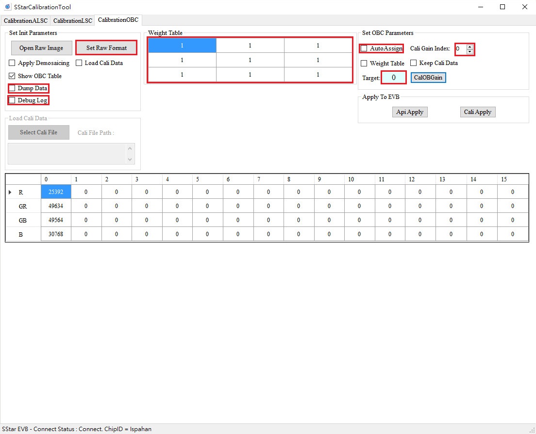
CalibrationOBC Usage and Parameter description
-
Parameter setting
Open Raw Image: Select the Raw image path.
Set Raw Format: Set Raw image related parameters.
Apply Demosaicing: Pass Raw image through simple Demosaic.
Show OBC Table: Display the table corrected by OBC.
CalOBGain: Generates the value of the corrected black current according to the input parameters.
ApiApply: Apply the correction results to the board.
CaliApply: Apply the calibration knot to the board.
Debug Log: You can see the debug log during CalOBGain and Apply.
Keep Cali Data: Load the generated .data data so that the previous results can be retained and continued to be calibrated.
Dump Data: txt file that generates calibration results.
Load Cali Data: Load the generated .data so that it can use CaliApply to apply the correction result of that .data.
Select Cali File: This option can only be clicked when Load Cali Data is checked, and is used to select the .data to be loaded onto the board.
Weight Table: Divide the image into 3×3 blocks. The weight of each block when calculating OB. The value range is 0 ~ 16. It is recommended to set all to 1.
AutoAssign: Set the OB value to all gains, the value range is 0 ~ 1, and it is recommended to set it to 1.
Cali Gain Index: Select which group of OB values to calibrate, the value range is 0 ~ 15.
SetOBCParameters-Weight Table: Display Weight Table.
Target: The desired residual value after calibration. The unit is 16-bit and the value range is 0 ~ 65535. It is recommended to set it to 0.
-
How to use
There are two routes depending on whether Load Cali Data is checked.
Checked:
-
After checking Load Cali Data, click Select Cali Data and select the .data you want to apply.
-
After selecting the desired .data, you can only use CaliApply. At this time, the calibration parameters of Apply will not be displayed on our SStarCalibrationTool.
Unchecked:
-
Click Set Raw Format to set the raw image information, and click Open Raw Image to open the raw image. You can check Apply Demosaicing to view the RGB image. This is just a simple demosaic function, which is different from the actual one. Whenever you uncheck Load Cali Data, you must click Open Raw Image again to open the raw image.
-
Set the parameters for generating the table, including Weight Table, Target, AutoAssign, and Cali Gain Index, and then click CalOBGain to generate the calibration table. You can check Show OBC Table to view the calibration table. When you have completed the calibration of the first set of parameters, if you want to keep the results and continue calibration, you can check Keep Cali Data.
-
Set the parameters downloaded to the board and click ApiApply or CaliApply to take effect. Please be sure to click Read on the OBC interface to see the same parameters as CalibrationOBC. After each Apply, CalOBGain, CaliApply and ApiApply will be grayed out. If the settings in the red box above are changed, you can recalibrate.
-
Raw Setting Parameter Interface
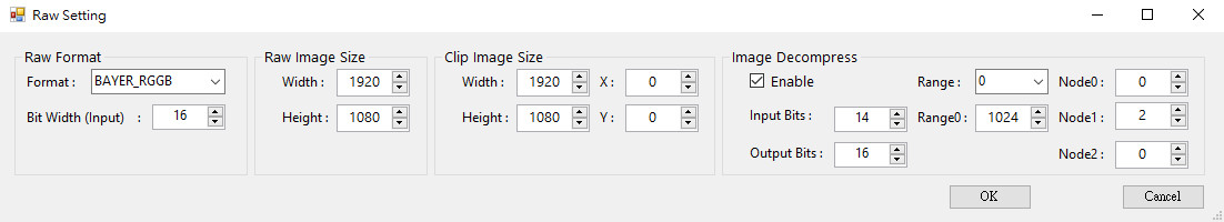
Raw Setting Parameter Description
-
Raw Format
-
Format: RGB format of the Raw image.
-
Bit Width (Input): Raw image input bits.
-
-
Raw Image Size
-
Width: The width of the Raw image.
-
Height: The height of the Raw image.
-
-
Clip Image Size
-
Width: The width of the Raw image after Clipping.
-
Height: The height of the Raw image after Clipping.
-
X: The width of the Raw image to be clipped. Note that the starting position plus the size of the Clip you want cannot exceed the size of the Raw image.
-
Y: The height of the Raw image to be clipped. Note that the starting position plus the size of the Clip you want cannot exceed the size of the Raw image.
-
-
Image Decompress
-
Enable: Whether to enable the Decompress function (corresponding to Parameter Description [DECOMP_INFO] decomp_enable).
-
Input Bits: The compressed bits (corresponding to Parameter Description [DECOMP_INFO] decomp_input_bits).
-
Output Bits: The decompressed bits (corresponds to Parameter Description [DECOMP_INFO] decomp_output_bits).
-
Range : There are a total of four ranges that need to be set.
-
Range0: Set the first range, 0 ~ Range0 (corresponding to Parameter Description [DECOMP_INFO] decomp_range0).
-
Range1: Set the second range, Range0 ~ Range1 (corresponding to Parameter Description [DECOMP_INFO] decomp_range1).
-
Range2: Set the third range, Range1 ~ Range2 (corresponding to Parameter Description [DECOMP_INFO] decomp_range2).
-
Range3: The fourth range does not need to be set, Range2 ~ ∞.
-
Node0: The range offset (corresponding to parameter description [DECOMP_INFO] decomp_rangeX_f0).
-
Node1: The range shift (corresponding to parameter description [DECOMP_INFO] decomp_rangeX_f1).
-
Node2: The range basis (corresponding to Parameter Description [DECOMP_INFO] decomp_rangeX_f2).
-
CALIBRATION TOOL 1.0.14.0
Supports OBC, ALSC, LSC and AWB production line calibration, and requires the use of an offline calibration tool. It is necessary to confirm whether the Visual Studio 20xx distributable package is installed in the computer environment (Link: x86, x64).
Calibration Flow
Capture Raw in each scenario, set parameters (modify *.ini), generate *.data, and burn the *.data.
How to capture Raw
Parameter Description
Set environment parameters in calibration\SampleCode\Release\CalibrationInitialParameter.ini
[RAW_INFO]
-
filename : Raw name.
Raw data naming convention is "filename" + "_" + "three numbers"
-
frame_numbers: The number of Raw frames for a single calibration, usually 1, except for SDC which often uses multiple frames for calibration.
-
frame_start_index : Raw number.
-
If filename = "SDC" and frame_start_index = 1, the Raw in the sample code must be named SDC_001.
-
If 3 Raw images are needed for calibration, filename = "SDC", frame_start_index = 2, frame_numbers = 3, then the Raw images must be named SDC_002, SDC_003, SDC_004.
-
-
width: The width of Raw image.
-
height: The height of Raw image.
-
clip_x: The starting X coordinate of the Clip image. To avoid destroying the Bayer Pattern sorting, it is recommended to set it to an even number.
-
clip_y: The starting Y coordinate of the Clip image. To avoid destroying the Bayer Pattern sorting, it is recommended to set it to an even number.
-
clip_width: The width of the Clip image. To avoid destroying the Bayer Pattern sorting, it is recommended to set it to an even number.
-
clip_height: The height of the Clip image. To avoid destroying the Bayer Pattern sorting, it is recommended to set it to an even number.
-
dump_clip_image: The switch for dumping clip image files. 0 means off, 1 means on, and the default value is 0.
-
cfa_type : The order of the Bayer pattern, that is, the color block in the upper left corner. [0 = RGGB, 1 = GRBG, 2 = BGGR, 3 = GBRG, 4 = RGBGGIGI(R0), 5 = GBGRIGIG(G0), 6 = BGRGGIGI(B0), 7 = GRGBIGIG(G1), 8 = GIGIRGBG(G2), 9 = IGIGGBGR(I0), 10 = GIGIBGRG(G3), 11 = IGIGGRGB(I1)]
-
source_type: Select 0 for Raw. Modification is not recommended.
-
in_data_precision: The precision of the input Raw data. The default value is 16.
-
out_data_precision : The precision of output *.data, the default value is 16.
-
cali_output_path: Output path, modification is not recommended.
[CALI_INFO]
-
calibration_select: Calibration item, AWB = 0, OBC = 1, SDC = 2, ALSC = 3, LSC = 4.
-
load_calibration_data: Load *.data switch. For the first calibration, it must be set to 0. If you want to perform multiple calibrations , you must set this to 1 from the second calibration onwards to save the previously calibrated data. This is commonly used in OBC, ALSC, LSC, AWB, and SDC. [This platform does not support the SDC function]
-
load_calibration_data: Twinkie = 2, Pretzel = 3, Macaron = 4, Pudding = 5, Ispahan = 6, Ikayaki = 7, Muffin = 8, Maruko = 9, Opera = 10, Mercury5 = 16, Tiramisu = 17.
[CALI_DB]
-
cali_dump_data: Dump .txt switch. If you choose 0, only *.data will be generated; if you choose 1, in addition to *.data, *.txt will also be stored.
-
cali_xxx_xxx_path: The corrected *.data path. It is not recommended to modify.
[DECOMP_INFO]
-
decomp_enable: Switch to decompress Raw.
-
decomp_input_bits: The actual number of bits after the input Raw is compressed. Please note that [RAW_INFO] in_data_precision must be set to 16 at this time.
The following are decompress parameters:
-
decomp_range0_f0: f0r0
-
decomp_range0_f1: f1r0
-
decomp_range0_f2: f2r0
-
decomp_range0: r0
-
decomp_range1_f0: f0r1
-
decomp_range1_f1: f1r1
-
decomp_range1_f2: f2r1
-
decomp_range1 : r1
-
decomp_range2_f0 : f0r2
-
decomp_range2_f1 : f1r2
-
decomp_range2_f2 : f2r2
-
decomp_range2 : r2
-
decomp_range3_f0 : f0r3
-
decomp_range3_f1 : f1r3
-
decomp_range3_f2 : f2r3
Please refer to the following formula:
(pixel - f0r0) ≪ f1r0 + f2r0, if pixel ≤ r0
(pixel - f0r1) ≪ f1r1 + f2r1, if r0 < pixel ≤ r1
(pixel - f0r2) ≪ f1r2 + f2r2, if r1 < pixel ≤ r2
(pixel - f0r3) ≪ f1r3 + f2r3, if r2 < pixel
[OBC] [ALSC] [LSC] [AWB]: Detailed introduction will be given in the following chapters.
Generate *.data
Calibration Step:
-
Put the Raw used for calibration in calibration\SampleCode\Release\image.
-
Modify calibration\SampleCode\Release\CalibrationInitialParameter.ini.
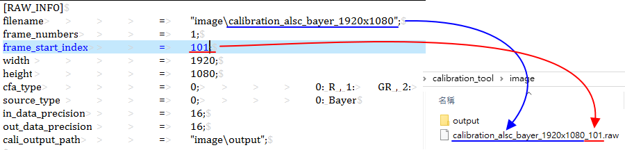
-
Execute calibration\SampleCode\Release\CalibrationRelease.exe.
At the beginning of the calibration process, the execution path directory will be checked to see if the data and image folders exist (automatically generated).
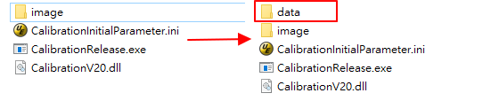
-
After the calibration process is successful, you can obtain *.data in calibration\SampleCode\Release\data\cfg.
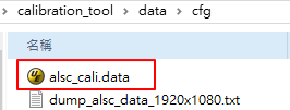
Load *.data
You can use MI_ISP_ApiCmdLoadCaliData to load calibration data. For details, please refer to ISP Software Development Guide.
OBC Adjustments
Calibrate the black level of the sensor.
Calibration Environment
The calibration environment is blacked out, and any possible light source must be avoided. When blacked out, first observe whether there is any abnormality in the streaming image. If there is no abnormality, proceed to the next step. If an abnormality is found, suspend the calibration and report it immediately. Wait until the problem is solved before taking subsequent actions.
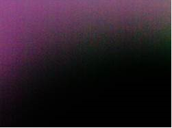
Parameter Description
AutoAssign: Set the OB value to all gains, the value range is 0 ~ 1, and it is recommended to set it to 1.
Target: The desired residual value after calibration, in 16-bit units, with a range of 0 to 65535. It is recommended to set it to 0.
Weight: Divide the image into 3×3 blocks. The weight of each block when calculating OB. The value range is 0 ~ 16. It is recommended to set all to 1.
CaliGainIndex: Enter the value according to ISO index, ranging from 0 to 15.
Calibration Steps
-
Set the total gain to the minimum ratio, mask the image and capture the Raw.
-
If it is normal mode or combine mode, out_data_precision is filled with 16.
-
Generate obc_cali.data, and you can also generate dump_obc_data.txt to view the calibration results, and then load obc_cali.data into it.
-
If it is normal mode or combine mode, the OB value will be filled in the blacklevel of the OBC interface in IQtool in 16-bit units.
-
If in HDR mode, long and short exposures must be calibrated separately
-
Short exposure correction: Same as normal mode, cover black and capture short exposure Raw, and fill out_data_precision with 16 to generate obc_cali.data. Then load obc_cali.data into it, and the OB value will be filled in the blacklevel of the OBC interface in IQtool in 16-bit.
-
Long exposure correction: mask black and capture the long exposure Raw, and fill out_data_precision with 16 to generate dump_obc_data.txt, and then manually fill it into the blacklevel_1 of the OBC interface in IQtool, the unit is 16-bit.
Remark:
A. Normal mode: Indicated as Linear mode (single frame) and HDR mode (2 frames).
B. Combine mode: Indicates that the Sensor end completes the synthesis of long and short exposure images, including the image data compression program.
-
Notes
-
If the OBs of high-gain and low-gain are very different and you need to set different OBs for different ISO indexes, please use AE to manually set the gain values of each ISO index, mask and shoot Raw, generate dump_obc_data.txt, and then manually fill it into the 16 nodes of Auto Mode of blacklevel in the OBC interface of IQtool.
-
After OBC calibration is completed, check whether the Gr/Gb values are consistent, mainly to avoid the CrossTalk phenomenon.
It is recommended to manually adjust Gr = Min(Gr, Gb) and Gb = Min(Gr, Gb).
.data format & size
Handle size: 20 bytes
Ctrl size: 32 bytes
Data size: 128 bytes
Total size: 20 + 32 + 180 bytes
ALSC Adjustment
Different lens and sensor combinations will result in different Y shading & color shading phenomena, so when the lens or sensor is replaced, it is necessary to evaluate whether recalibration is needed.
ALSC correction will generate a 27×17 table for R, G, and B, and give different R, G, and B gains to different areas of the picture. Therefore, Y shading & color shading can be improved at the same time. It supports up to 3 color temperatures and does not support table interpolation.
Calibration Environment
The most rigorous method for uniform light source is to use a Macbeth standard light box with a diffuser for calibration. If there is no diffuser, you can only calibrate the gray wall in the light box to make the light as uniform as possible.
Before adjustment, make sure that the OB and AWB color temperature curve ranges have been calibrated and applied. When using the RGB sensor, make sure that the IR cut is covered.
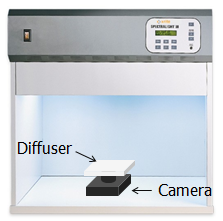
Parameter Description
TargetIndex: Select the table group to be calibrated. Up to 3 groups are supported. The calibration order does not need to follow the order from 0 to 2, but it is necessary to ensure that the ambient color temperature from 0 to 2 is from low to high.
CCTNumber: Select how many sets of color temperature table data to calibrate in total. The default is to calibrate 3 sets of color temperature tables, with a value range of 1 to 3.
GridX/Y: The size of the Shading Table, which is preset to 27x17 on this platform.
GridNumMax: The maximum table size of the Shading Table, which is a fixed value. On this platform, it is 27x17=459.
Segment_Delta_Str_Mode: There are 16 preset modes. The vertical axis represents each mode, and the horizontal axis represents the size of each grid spacing in the X/Y direction. In this platform, the spacing is X = 26 and Y = 16 grids. The larger the value in the default mode, the smaller the surrounding grids. The value range is 0 ~ 15.
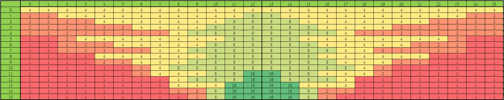
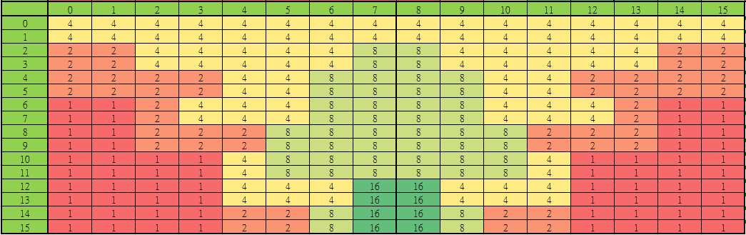
ColorTemperature : The ambient color temperature at the current TargetIndex.
OB_R/G/B_Value: The current sensor's OB value, in 16-bit units, ranging from 0 to 65535.
RatioTable_R/G/B'Num': The correction strength ratio from the center to the corner of the image, with a value range of 0 ~ 255.
Note: 'Num' represents the numerical number, 0 represents the center of the screen, and 8 represents the four corners.
UnitGainResult: Select whether to generate a 1x gain Shading Table, 0 means off, 1 means on, the value range is 0 ~ 1.
PortraitEnable: Check the image width and height, 0 means disabled, 1 means enabled, the value range is 0 ~ 1.
Segment_Delta_Adv_Enable : Select the advanced mode switch, 0 means off, 1 means enabled, the value range is 0 ~ 1. When GridX/Y is not 27x17 on this platform, this advanced mode → non-equidistant grid setting must be used.
Segment_Delta_LUT_X0~8: X-axis spacing, each 4 bits is represented as a set of index values [index = (block size / 16) - 1], then the actual number of pixels is (index + 1) x 16. The index value is limited to 1, 2, 4, 8, and 16. If it is not used, it is set to 0. It supports up to 72 groups. On this platform, the space is 26 grids.
Segment_Delta_LUT_Y0~8: Y-axis spacing, each 4 bits are represented as a set of index values [index = (block size / 16) - 1], then the actual number of pixels is (index + 1) x 16. The index value can only be filled in 1,2,4,8,16. If it is not used, it is set to 0. It supports up to 72 groups. On this platform, the spacing is 16 grids.
Calibration Steps
-
First decide how many light sources you want to calibrate, set the AE target to about 1500 to shoot Raw data of various color temperatures, and make sure the raw data is not overexposed, and put the file into the image folder of the calibration tool [Note: AE target data range = 10 ~ 2550].
-
Open CalibrationInitialParameter.ini and fill in the correct [RAW INFO] (refer to Raw mode parameter description).
-
Raw data path and format.
-
Set in/out_data_precision to 16.
-
Set calibrarion_select to 4.
-
When calibrating the first color temperature, load_calibration_data should be set to 0, and when calibrating the remaining color temperatures, load_calibration_data should be set to 1.
-
-
Set the [ALSC] calibration parameters in CalibrationInitialParameter.ini (refer to ALSC adjustment parameter description).
-
Execute CalibrationRelease.exe to generate alsc_cali.data.
-
Repeat steps 2, 3, and 4 to calibrate all color temperatures and generate the final alsc_cali.data. If cali_dump_data in [CALI_DB] is set to 1 during calibration, dump_alsc_data.txt will be generated after calibration, in which you can see the calibrated shading table values.
-
You need to use the MI_ISP_ApiCmdLoadCaliData API to apply alsc_cali.data. (For details, please refer to the document ISP Software Development Guide)
Adjustment Interface
Click Shading in the left menu and the ALSC and ALSC_CTRL interfaces will appear.
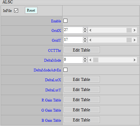
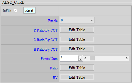
Parameter Description
R Gain Table: ALSC R table, value range 0 ~ 8191.
G Gain Table: ALSC G table, value range 0 ~ 8191.
B Gain Table: ALSC B table, value range 0 ~ 8191.
R Ratio By CCT: ALSC table overall R ratio value (128 = 1x), value range 0 ~ 128.
G Ratio By CCT: ALSC table overall G ratio value (128 = 1x), value range 0 ~ 128.
B Ratio By CCT: ALSC table overall B ratio value (128 = 1x), value range 0 ~ 128.
Points Num: The number of nodes set by Ratio by BV (Different Ratios are set according to different ambient brightness values (BV)).
Ratio : Ratio value of each node. 0~27 only deducts chroma, 28~128 deducts chroma and luma.
BV: The BV value corresponding to each node.
Adjustment Steps
-
Adjust the Ratio at different BVs. Usually, the Ratio will be reduced at low BVs to reduce the dirtiness of the outer ring caused by ALSC.
-
The R/G/B Ratio By CCT is preset to 1x. You can adjust it if necessary.
Notes
The ALSC R/G/B Gain table exists in both iqfile and alsc_cali.data, but the API bin can only be read and written and is not stored in the API bin (because the size is too large). Therefore, alsc_cali.data needs to be loaded every time the computer is turned on.
.data format & size
Handle size: 20 bytes
Ctrl size: 52 bytes
Data size: 4 + x bytes, x = (GridX*GridY*3*2 + 2*GridMax)/4, unconditionally carry the decimal value and multiply it by 4 GridMax = the larger of GridX or GridY
Total size: 20 + 52*cctNum + (4 + x)*cctNum bytes, cctNum = the number of color temperature groups to be corrected (1 ~ 3)
LSC Adjustment
LSC correction will generate a 32-table for each of R, G, and B, and give different R, G, and B gains to different areas of the picture, so that Y shading can be improved at the same time. It supports up to 3 color temperatures and does not support table interpolation.
Calibration Environment
Same as ALSC.
Parameter Description
TargetIndex: Select the table group to be calibrated. Up to 3 groups are supported. The calibration order does not need to follow the order from 0 to 2, but it is necessary to ensure that the ambient color temperature from 0 to 2 is from low to high.
CCTNumber: Select several sets of color temperature table data to calibrate. The default is to calibrate 3 sets of color temperature tables, with a value range of 1 to 3.
TableSize: The size of the Shading Table, the default value is 32. It is not recommended to modify this value.
LSCResult: Dump LSC result image.
SegmentLength: The length of the cutting sampling point
AutoCenter: Select to automatically detect the brightest center point of the input image. The value range is 0 ~ 1. It is recommended to set it to 1. If set to 0, use the following InputOrientation and InputCenterX/Y manual settings.
InputOrientation: Set the sampling point direction, from the brightest center point of the image to the corner point. 0: upper-left, 1: upper-right, 2: lower-right, 3: lower-left
InputCenterX/Y : Set the brightest center point of the image, value range: 0 ~ 4095.
ColorTemperature : The ambient color temperature at the current TargetIndex.
OB_R/G/B_Value: The current sensor's OB value, in 16-bit units, value range: 0 ~ 65535.
RatioTable_R/G/B'Num': The correction strength ratio from the center to the corner of the image, with a value range of 0 ~ 255. Note: 'Num' represents the numerical number, and the value range is 0 ~ 8.
Ratio_Threshold: It is used to prevent over-compensation of vignetting. The larger the value, the more vignetting compensation, and the smaller the value, the less compensation. The more vignetting compensation, the more normal data near the corner will be over-compensated. When the threshold is smaller, the compensation value will be set to the maximum value according to the current maximum index value, and the index value after the maximum index value will maintain the maximum compensation value (no increase in value); on the contrary, the larger the threshold value, the larger the compensation value. Ratio Base = 100, the value range is 0 ~ 25600.
DebugLSCInfo: Only applicable to Debug mode, it can provide relevant error messages to manufacturer for problem analysis. 0 means off, 1 means on, the value range is 0 ~ 1, and it is recommended to set it to 0.
Calibration steps
-
Same as ALSC.
-
Generate lsc_cali.data, or dump_lsc_data.txt or dump_lsc_result.raw to view the calibration results, and then load lsc_cali.data into it. If there is no LSC calibration, this step can be skipped and jump to the next item.
Adjustment interface
Click Shading in the left menu and the LSC and LSC_CTRL interfaces will appear.
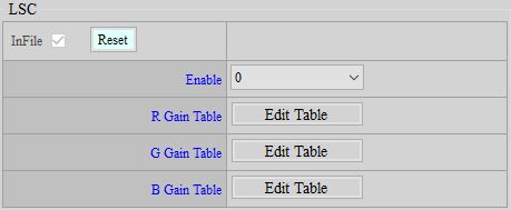
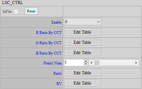
Parameter Description
R Gain Table: LSC R table, value range 0 ~ 1023.
G Gain Table: LSC G table, value range 0 ~ 1023.
B Gain Table: LSC B table, value range 0 ~ 1023.
R Ratio By CCT : LSC table overall R ratio value (128 = 1x), value range 0 ~ 128.
G Ratio By CCT: LSC table overall G ratio value (128 = 1x), value range 0 ~ 128.
B Ratio By CCT: LSC table overall B ratio value (128 = 1x), value range 0 ~ 128.
Points Num: The number of nodes set by Ratio by BV (different Ratios are set according to different ambient brightness values (BV)).
Ratio: Ratio value of each node.
BV: The BV value corresponding to each node.
Adjustment Steps
-
Adjust the Ratio at different BVs. Usually, the Ratio will be reduced at low BVs to reduce the dirtiness of the outer ring caused by LSC.
-
The R/G/B Ratio By CCT is preset to 1x. You can adjust it if necessary.
-
If necessary, you can directly adjust the R/G/B Gain table.
Notes
-
If the LSC R/G/B Gain table exists in iqfile, lsc_cali.data, and API bin at the same time, iqfile will be used as the default value. If API bin exists, iqfile will be overwritten. If lsc_cali.data exists, API bin will be overwritten.
-
The normal process is to load lsc_cali.data first, which will store the LSC R/G/B Gain table in the API bin. You can then adjust it directly on the API, and there is no need to reload lsc_cali.data every time.
.data format & size
Handle size: 20 bytes.
Ctrl size: 60 bytes.
Data size: 8 + x bytes, where x = the unconditional carry value of the decimal of (2 + TableSize * 3 * 2) / 4 multiplied by 4.
Total size: 20 + 60 * + (8 + x) * cctNum bytes, cctNum = the number of corrected color temperature groups (1 ~ 3).
AWB Adjustment
Used for production line calibration to compensate for the difference in white balance statistics between each machine and the Golden sample.
Calibration Environment
Place a gray card in the light box and let the gray card fill the entire screen to capture raw data.
Parameter Description
HighLowCTMode : Whether to use high and low color temperature correction (old correction method).
0 means OFF, and this mode is recommended for stitching correction;
1 means ON.
CaliState : Specifies the calibration mode (behavior varies depending on HighLowCTMode).
HighLowCTMode = 0
0 means CALIB_GOLDEN;
1 indicates CALIB.
HighLowCTMode = 1
0 means CALIB_GOLDEN_H;
1 means CALIB_GOLDEN_L;
2 means CALIB_H;
3 indicates CALIB_L.
BrightnessCaliMode: Whether to correct brightness (only works when HighLowCTMode = 0).
0 means OFF;
1 means ON.
CT: Color temperature (only works when HighLowCTMode = 0), value range 1000 ~ 10000.
CaliNumber: The total number of color temperatures to be corrected (only works when HighLowCTMode = 1). A maximum of 2 color temperatures are supported, value range 1 ~ 2.
HighCT: High color temperature (effective only when HighLowCTMode = 1), value range 1000 ~ 10000.
LowCT: Low color temperature (only works when HighLowCTMode = 1), value range 1000 ~ 10000.
OB_R/GR/GB/B_Value: OB value setting, value range 0 ~ 65535.
Calibration Steps
HighLowCTMode = 0
-
Analyze the AWB statistical values of multiple machines and select one that is close to the average value as the golden sample.
-
When calibrating, choose to use a color temperature light source for calibration. The calibration process is as follows:

-
Use the golden sample and unit sample to capture raw data and put them into the image folder of the calibration tool.
-
Open CalibrationInitialParameter.ini and fill in the correct [RAW INFO] (refer to Raw capture parameter description).
-
Golden sample raw data path and format.
-
Set in/out_data_precision to 16.
-
Set calibrarion_select to 2.
-
Set load_calibration_data to 0.
-
-
Set the [AWB] calibration parameters in CalibrationInitialParameter.ini (refer to AWB calibration parameter description).
-
Set CaliState to 0.
-
Set BrightnessCaliMode to 0 or 1, depending on whether to calibrate brightness.
-
Set CT to the color temperature of the calibration light source.
-
OB value setting, value range 0 ~ 65535.
-
-
Execute CalibrationRelease.exe to generate awb_cali.data in \data\cfg containing the golden sample calibration values. This data must be saved until the calibration is completed.
-
Open CalibrationInitialParameter.ini and fill in the correct [RAW INFO] (refer to Raw capture parameter description).
-
Unit sample raw data path and format.
-
Set in/out_data_precision to 16.
-
Set calibrarion_select to 2.
-
Set load_calibration_data to 1 to save the previously calibrated data.
-
-
Set the [AWB] calibration parameters in CalibrationInitialParameter.ini (refer to AWB calibration parameter description).
-
Set CaliState to 1.
-
Set BrightnessCaliMode to 0 or 1, depending on whether to calibrate brightness.
-
Set CT to the color temperature of the calibration light source.
-
OB value setting, value range 0 ~ 65535.
-
-
Execute CalibrationRelease.exe to generate the final awb_cali.data in \data\cfg to complete the calibration. If cali_dump_data in [CALI_DB] is set to 1 during calibration, dump_awb_data.txt will be generated after calibration, in which the calibrated values can be seen.
-
When calibrating the next unit sample, just load the awb_cali.data calibrated by the previous unit sample and then execute State 1 to overwrite the calibration result of the previous unit sample.
-
You need to use the MI_S32 MI_ISP_ApiCmdLoadCaliData API to apply awb_cali.data. (For details, please refer to the document ISP Software Development Guide)
-
HighLowCTMode = 1
-
Analyze the AWB statistical values of multiple machines and select one that is close to the average value as the golden sample.
-
When calibrating, you can choose to use one or two color temperature light sources for calibration.
A. Assuming that only one light source is used for calibration, the calibration process is as follows:
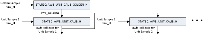
-
Use the golden sample and unit sample to capture raw data and put it into the image folder of the calibration tool.
-
Open CalibrationInitialParameter.ini and fill in the correct [RAW INFO] (refer to Raw capture parameter description).
-
Golden sample raw data path and format.
-
Set in/out_data_precision to 16.
-
Set calibrarion_select to 2.
-
Set load_calibration_data to 0.
-
-
Set the [AWB] calibration parameters in CalibrationInitialParameter.ini (refer to AWB calibration parameter description).
-
Set CaliState to 0.
-
Set CaliNumber to 1.
-
Set HighCT to the color temperature value of the calibration light source.
-
OB value setting, value range 0 ~ 65535.
-
-
Execute CalibrationRelease.exe to generate awb_cali.data in \data\cfg containing the golden sample calibration values. This data must be saved until the calibration is completed.
-
Open CalibrationInitialParameter.ini and fill in the correct [RAW INFO] (refer to Raw capture parameter description).
-
Unit sample raw data path and format.
-
Set in/out_data_precision to 16.
-
Set calibrarion_select to 2.
-
Set load_calibration_data to 1 to save the previously calibrated data.
-
-
Set the [AWB] calibration parameters in CalibrationInitialParameter.ini (refer to AWB calibration parameter description).
-
Set CaliState to 2.
-
Set CaliNumber to 1.
-
Set HighCT to the color temperature value of the calibration light source.
-
OB value setting, value range 0 ~ 65535.
-
-
Execute CalibrationRelease.exe to generate the final awb_cali.data in \data\cfg to complete the calibration. If cali_dump_data in [CALI_DB] is set to 1 during calibration, dump_awb_data.txt will be generated after calibration, in which you can see the calibration results.
-
When calibrating the next unit sample, just load the awb_cali.data calibrated by the previous unit sample and then execute State 2 to overwrite the calibration result of the previous unit sample.
-
You need to use the MI_S32 MI_ISP_ApiCmdLoadCaliData API to apply awb_cali.data. (For details, please refer to the document ISP Software Development Guide)
B. Calibration If two light sources are used for calibration, the calibration process is as follows:
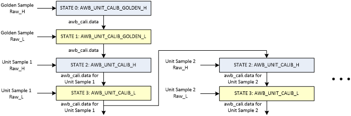
-
Use golden sample and unit sample to capture raw data of two color temperatures and put them into the image folder of the calibration tool.
-
Open CalibrationInitialParameter.ini and fill in the correct [RAW INFO] (refer to Raw capture parameter description).
-
Golden sample high color temperature raw data path and format.
-
Set in/out_data_precision to 16.
-
Set calibrarion_select to 2.
-
Set load_calibration_data to 0.
-
-
Set the [AWB] calibration parameters in CalibrationInitialParameter.ini (refer to AWB calibration parameter description).
-
Set CaliState to 0.
-
Set CaliNumber to 2.
-
Set HighCT to the color temperature value of the calibration light source.
-
OB value setting, value range 0 ~ 65535.
-
-
Execute CalibrationRelease.exe to generate awb_cali.data in \data\cfg, which contains the golden sample high color temperature calibration value. This data must be saved until the calibration is completed.
-
Open CalibrationInitialParameter.ini and fill in the correct [RAW INFO] (refer to Raw capture parameter description).
-
Golden sample low color temperature raw data path and format.
-
Set in/out_data_precision to 16.
-
Set calibrarion_select to 2.
-
Set load_calibration_data to 1.
-
-
Set the [AWB] calibration parameters in CalibrationInitialParameter.ini (refer to AWB calibration parameter description).
-
Set CaliState to 1.
-
Set CaliNumber to 2.
-
Set LowCT to the color temperature value of the calibration light source.
-
OB value setting, value range 0 ~ 65535.
-
-
Execute CalibrationRelease.exe to generate awb_cali.data in \data\cfg, which contains the high and low color temperature calibration values of the golden sample. This data must be saved until the calibration is completed.
-
Open CalibrationInitialParameter.ini and fill in the correct [RAW INFO] (refer to Raw capture parameter description).
-
Unit sample high color temperature raw data path passed Mode.
-
Set in/out_data_precision to 16.
-
Set calibrarion_select to 2.
-
Set load_calibration_data to 1 to save the previously calibrated data.
-
-
Set the [AWB] calibration parameters in CalibrationInitialParameter.ini (refer to AWB calibration parameter description).
-
Set CaliState to 2.
-
Set CaliNumber to 2.
-
Set HighCT to the color temperature value of the calibration light source.
-
OB value setting, value range 0 ~ 65535.
-
-
Execute CalibrationRelease.exe to generate awb_cali.data in \data\cfg, which contains the golden sample high and low color temperature calibration values and the unit sample high color temperature calibration value. This data must be saved until the calibration is completed.
-
Open CalibrationInitialParameter.ini and fill in the correct [RAW INFO] (refer to Raw capture parameter description).
-
Unit sample low color temperature raw data path and format.
-
Set in/out_data_precision to 16.
-
Set calibrarion_select to 2.
-
Set load_calibration_data to 1 to save the previously calibrated data.
-
-
Set the [AWB] calibration parameters in CalibrationInitialParameter.ini (refer to AWB calibration parameter description).
-
Set CaliState to 3.
-
Set CaliNumber to 2.
-
Set LowCT to the color temperature value of the calibration light source.
-
OB value setting, value range 0 ~ 65535.
-
-
Execute CalibrationRelease.exe to generate the final awb_cali.data in \data\cfg to complete the calibration. If cali_dump_data in [CALI_DB] is set to 1 during calibration, dump_awb_data.txt will be generated after calibration, in which the calibrated values can be seen.
-
When calibrating the next unit sample, just load the awb_cali.data calibrated by the previous unit sample and then execute State 2 & 3 to overwrite the calibration result of the previous unit sample.
-
You need to use the MI_ISP_ApiCmdLoadCaliData API to apply awb_cali.data. (For details, please refer to the document ISP Software Development Guide)
-
.data format & size
HighLowCTMode = 0
Handle size: 20 bytes
Ctrl size: 24 bytes
Data size : 12 bytes
Total size: 20 + 24 + 12 bytes
HighLowCTMode = 1
Handle size: 20 bytes
Ctrl size: 28 bytes
Data size: 16 bytes
Total size: 20 + 28 + 16 bytes
SDC Adjustment
Bad pixel compensation can compensate black and white points.
Calibration Environment
Cover the black and grab Raw (same as OB), illuminate evenly and grab Raw (same as ALSC).
Parameter Description
Item: To cover the black and capture the Raw white point, select 0; to illuminate the uniform light source and capture the Raw black point, select 1; to mix the first two results, select 2.
MixerRatio: The ratio of white point to black point. It is only valid when Item = 2. 100 means taking all the results of Item = 0, and 0 means replacing all the results of Item = 1.
CaliImgNum: The number of corrected Raw images, must be the same as frame_numbers.
TableSize : 256.
InvalidRatio: Set the ratio value for filtering out the search range. The value range is 0 ~ 100. It is recommended to set it to 0.
CaliFlag : Set whether to determine clustered bad pixels in the image, 0 means Disable, 1 means Enable, the value range is 0 ~ 1. (For versions after 1.0.1.0, this parameter is invalid, and the algorithm is Default ON)
ValidValue: Output parameter, showing the pixel value of the N+1 bad pixel in the image after bad pixel compensation, where N represents the number of bad pixels compensated.
ClusterAmount: Output parameter, which calculates the number of bad pixel points that are judged as clusters.
TotalAmount: Output parameter, showing the total number of bad pixel points detected.
BadPixelTh: Set the condition for judging a bad pixel, the value range is 0 ~ 1000, the larger the value, the harder it is to judge a bad pixel. (Versions after 1.0.9.0 support this feature)
Calibration Steps
When capturing RAW images to correct bad pixels, you can correct only black or white pixels, or a mixed black and white pixel result. The main settings to pay attention to are as follows.
A. White Point
Step 1: Item = 0, load_calibration_data = 0;
Step 2: Item = 2, load_calibration_data = 1, MixerRatio = 100.
B. Black spot calibration
Step 1: Item = 1, load_calibration_data = 0;
Step 2: Item = 2, load_calibration_data = 1, MixerRatio = 0.
C. Mix white and black dots
Step 1: Item = 0, load_calibration_data = 0;
Step 2: Item = 1, load_calibration_data = 1;
Step 3: Item = 2, load_calibration_data = 1, MixerRatio (adjust according to the required ratio).
If you still see white spots after covering the black area, or if you still see black spots after illuminating the area with uniform light, and the bad pixels are still not compensated, please report it to manufacturer.
.data format & size
Handle size : 20 bytes
Ctrl size: 44 bytes
Data size: 6144 bytes
Total size: 20 + 44 + 6144 bytes
Differences with MACARON
| Module Name | Difference Function | Difference Parameters (Deleted) | Difference Parameters (Newly Added) |
|---|---|---|---|
| HDR | Added ghost compensation | u16SensorExpRatio bDynRatioEn u8CRefSel |
u16NoiseLevel[16] u16MotionTh u16MotionAdjLut[7] |
| HDR Ex | Added ghost compensation | Added API | |
| 3DNR | Added perturbation to reduce motion noise | u16MdThd u8TfLut[16] u8YSfStr |
u8MdThd u16TfLut[16] u8YSfBlendOffset |
| 3DNR EX | Added purple fringing area noise processing to optimize pink smear in high brightness areas | Added API | |
| Crosstalk | Added adjusting strength based on brightness | u8StrengthV2 u16ThresholdV2 u16ThresholdOffsetV2 |
u8Strength u8Threshold u16Offset u8StrengthByY[15] |
| NRDeSpike | Added the ability to adjust DPC strength based on diff and brightness | u16DiffGainCenterNeighbor u16DiffThdCornerCross |
u8DiffGainCenterNeighbor u8DiffThdCornerCross u16BlendLut[5] u8StrengthByY[15] |
| NRLuma | Optimize the pre-stage YNR processing | bLumaAdjEn u8LumaX[9] u16LumaStrByY[10] u8Wei[20] |
u8Strength u8GMaskSel u16SpfBlendLut[2] |
| NRLuma Adv | Added post-stage YNR processing | Added API | |
| NRChroma Adv | Added pre-stage CNR processing | Added API | |
| Sharpness | Optimize the high-frequency area of Edge | stEdgeCtrl stTextureCtrl u8EdgeKillLUT bDirEn u16SharpnessUD u16SharpnessD |
u16EdgeKillLUT u16SharpnessUD[2] u16SharpnessD[2] u8PreCorUD[2] u8PreCorD[2 ] u8PreCorMotGain u8LpfEdgeGainUD u8LpfEdgeGainD u8WeakDetailEnhance u8DetailMotOffset u8MotGain[16] |
| Sharpness Ex | Optimize high-frequency areas of Edge | Added API | |
| PFC | Added the function of removing purple fringing | Added API | |
| PFC Ex | Added the function of removing purple fringing | Added API |