Touch Driver Integration Reference
1. Kernel driver adaptation
This article uses the gt911 IC as an example, which is customized based on the kernel's native goodix code and used directly. After confirmation, the main points that need to be modified are as follows:
-
There is no kernel-adapted GPIO controller on the sstar platform, so the API devm_gpiod_get_optional cannot be used to directly obtain the GPIO in the dts. The current method is to directly obtain the GPIO hardware number through the configuration macro, so the GPIO ID is obtained as a DTS attribute value.
-
On the sstar platform, the power supply of gt911 IC is usually always on, so the power supply related operations can be ignored.
2. config macro enabled
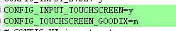
Normally, you need to enable the touch screen related config macros, but at the same time, you need to confirm whether the I2C config macro of the SSTAR platform is also enabled normally. Otherwise, although the driver will be compiled, it will still not run because there is no I2C Adapter. The specific macro configuration can be referred to as follows.
goodix.ko depends on firmware_class.ko, and the config corresponding to firmware_class.ko is CONFIG_FW_LOADER
3. DTS Adaptation
For a touch screen, there are three main points that need to be configured:
-
I2C adapter related configuration;
-
Power configuration of touch screen (optional);
-
Configuration of interrupt pin and reset pin of touch screen.
3.1 I2C adapter related configuration
This section introduces the I2C adapter-related configurations for the Comake PI D1 board and the SSM001A public board.
3.1.1 Comake PI D1 configuration
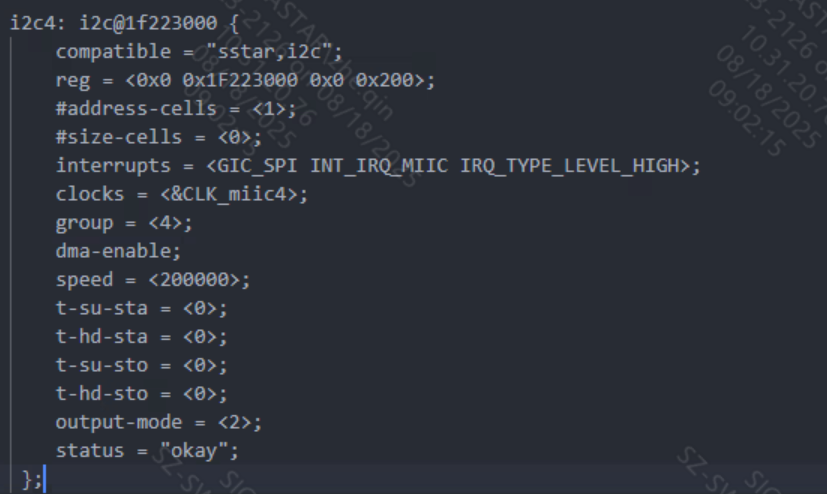
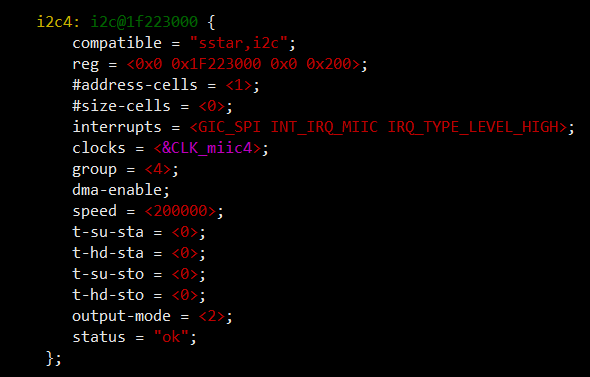
Generally speaking, the relevant configurations of the I2C adapter are configured by default in the platform's DTS, as follows:
At the same time, you need to pay attention to whether the SDA and SCL pins of I2C are configured as I2C mode in padmux. If they are not configured as I2C function pins, they need to be modified to the correct I2C pin mode. For reference, refer to the following:

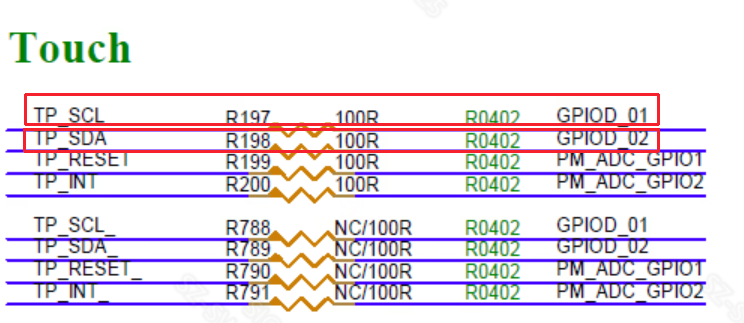
The pin names of PAD_GPIOD_01 and PAD_GPIOD_02 can be obtained from the schematic diagram:
Once you find the pin name, you can configure it in the pcupid-comake-pi-d1-dual-sensor-padmux.dtsi file.
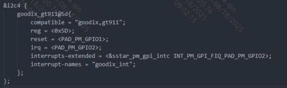
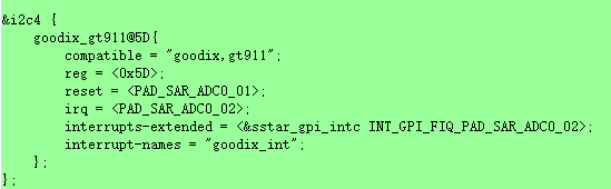
The interrupt pin and reset pin configuration of the touch screen can be referred to as follows. Because there is no GPIO controller, it is not configured in the form of standard GPIO pin configuration, but can be directly obtained as attribute value.
The GPIO values of the interrupt pin and reset pin are also obtained through the schematic diagram, as follows:
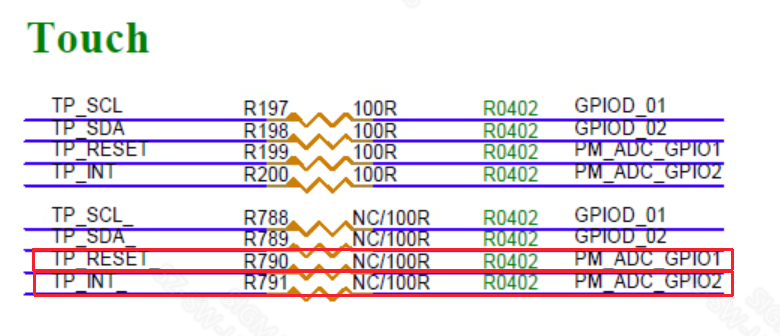
TP_RESET corresponds to reset PAD_PM_GPIO1
TP_INI corresponds to irq PAD_PM_GPIO2
The control of interrupts can be broken down into the following:
interrupts-extended = <&sstar_pm_gpi_intc INT_PM_GPI_FIQ_PAD_PM_GPIO2>;
sstar_pm_gpi_intc: corresponding interrupt controller
INT_PM_GPI_FIQ_PAD_PM_GPIO2: The corresponding ID of the interrupt controller, usually the INT_GPI_FIQ_ prefix plus the GPIO ID behind it
interrupt-names = "goodix_int" ;
goodix_int: interrupt name, you can choose any
3.1.2 ssm001a configuration
Generally speaking, the relevant configurations of the I2C adapter are configured by default in the platform's DTS, as follows:
At the same time, you need to pay attention to whether the SDA and SCL pins of I2C are configured as I2C mode in padmux. If they are not configured as I2C function pins, they need to be modified to the correct I2C pin mode. For reference, refer to the following:

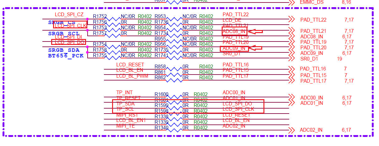
The pin names of PAD_SAR_ADC0_08 and PAD_SAR_ADC0_09 can be obtained from the schematic diagram:
Once you find the pin name, you can configure it in the pcupid-ssm001a-s01a-padmux file.
The interrupt pin and reset pin configuration of the touch screen can be referred to as follows. Because there is no GPIO controller, it is not configured in the form of standard GPIO pin configuration, but can be directly obtained as attribute value.
The GPIO values of the interrupt pin and reset pin are also obtained through the schematic diagram, as follows:
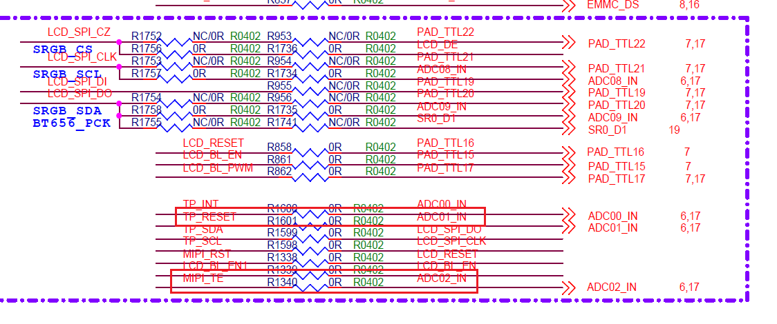
TP_RESET corresponds to reset PAD_SAR_ADC0_01
MIPI_TE corresponds to irq PAD_SAR_ADC0_02
The control of interrupts can be broken down into the following:
interrupts-extended = <&sstar_gpi_intc INT_GPI_FIQ_PAD_SAR_ADC0_02>;
sstar_gpi_intc: corresponding interrupt controller
INT_GPI_FIQ_PAD_SAR_ADC0_02: The corresponding ID of the interrupt controller, usually the INT_GPI_FIQ_ prefix plus the GPIO ID behind it
interrupt-names = "goodix_int" ;
goodix_int: interrupt name, you can choose any
3.3 Touch driver demo
The demo location path:
sdk/verify/sample_code/source/pcupid/tp/tp_demo
For usage and introduction, please refer to: sdk/verify/sample_code/source/pcupid/tp/tp_demo/Readme.md
4. Common problems with TP driver debugging
4.1 I2C communication abnormality when insmod goodix.ko
err: i2c-4 err dma write transform len:0 != para_len:2
err:i2c-4 xfer error: -7
Goodix-TS 4-005d: i2c test failed attempt 1: -1
err: i2c-4 err dma write transform len:0 != para_len:2
err:i2c-4 xfer error: -7
Goodix-TS 4-005d: i2c test failed attempt 2: -1
Goodix-TS 4-005d: I2C communication failure: -1
Check whether the slave device is connected and whether the hardware status of the board is correct.
4.1 Symbols are missing when insmod goodix.ko
insmod: can't insert 'goodix.ko': unknown symbol in module or invalid parameter
Check if you have not insmod firmware_class.ko first, then directly insmod goodix.ko