RISCV_IR USER GUIDE
REVISION HISTORY
| Revision No. | Description | Date |
|---|---|---|
| 1.0 | 04/18/2023 | |
| 1.1 | 04/08/2025 |
1. OVERVIEW
Infrared Receiver (IR) is mainly used to analyze the signal sent by the infrared remote control, which is a series of binary pulse codes. In order to prevent the infrared signal from being interfered by other signals during wireless transmission, it is usually modulated at a specific carrier frequency (38KHZ) and then transmitted through the infrared transmitting diode. The IR receives the signal of the specific frequency after filtering out other clutter and restores it to a binary pulse code, that is, demodulation. The decoding methods supported by SigmaStar IR are Full, Raw, SW and RC, and the protocols supported are NEC, RC5 and RC6.
2. Keyword
None.
3. FUNCTION DESCRIPTION
3.1. Basic Function
-
Support 5 groups of IR hardware.
-
Pulse signals less than 170us will be filtered.
-
The default clock frequency is 12MHZ, and the clock adjustment is not supported.
-
Supported decoding modes are Full, Raw, SW and RC5 (note that RC6 software is not supported yet).
3.2. IR Decoding Method
SigmaStar's IR_IN signal can be decoded in four decoding modes: Full mode, Raw mode, SW mode, and RC mode.
When the IR_IN signal is in NEC/NEC-like format, Full/Raw/SW mode can be used for decoding.
When the IR_IN signal is in RC format, it can be decoded in RC/SW mode (currently the driver only supports RC5 format).
When the IR_IN signal is in other format, it can only be decoded in SW mode (it needs to be used with a decoder).
-
Full mode
The hardware can decode IR_IN signals in NEC/NEC-like format and identify user codes and key codes.
-
Raw mode
The hardware can decode IR_IN signals in NEC/NEC-like format, but cannot identify which part is the user code or key code, which needs to be determined by software.
-
SW mode
The hardware cannot identify any format from the IR_IN signal, and software is required to decode the signal format, user code and key code.
-
RC mode
The hardware can decode IR_IN signals in RC format and identify user codes and key codes.
As can be seen from the block diagram below, there are two main paths for infrared decoding. The upper path is Full/Raw/SW mode, and the lower path is RC mode.

3.3. Each Protocol Level Standard
NEC format:
-
Logic0: 0.56ms high + 0.56ms low
-
Logic1: 0.56ms high + 1.68ms low
-
Header code: 9ms high pulse
-
Off code: 4.5ms low pulse:
-
Customer code: 8-bits customer code + 8-bits inverse or 16-bits customer code
-
Command code: 8-bits command code + 8-bits inverse
-
Total cycle time: 108ms
-
Repeat key: 9ms Header code and 2.5ms Off code

Figure 2-2: NEC Format Standard
NEC-like format:
-
Logic0: short high + short low (usually 1:1)
-
Logic1: short high + long low (usually 1:3)
-
Header code: ultra long high width
-
Off code: ultra long low width
RC5 format:
-
Logic0: 888us high + 888us low (Manchester code)
-
Logic1: 888us low + 888us high (Manchester code)
-
Start bits: 2-bits logic1
-
Toggle bit: Inverted every time when the key is released and pressed again
-
Customer code: 5-bits customer code
-
Command code: 6-bits command code
-
Total cycle time: 114ms
-
If a key is held over 114ms, it will repeat the signal every cycle time

Figure 2-3: RC5 Format Standard
RC5-Extend format:
-
Same as RC5 expect the second bit of SB is represented the 6th bit of address code

Figure 2-4: RC5-Extend Format Standard
RC6 mode 0 format:
-
Logic0: 444us low + 444us high (Manchester code)
-
Logic1: 444us high + 444us low (Manchester code)
(Note the logic length is half of RC5 format and the level order is opposite)
-
Header code: 2.666ms high pulse + 888us low pulse
-
Start bit: 1-bit logic1
-
Mode bits: 3-bit logic0 (in mode 0)
-
Toggle bit: Inverted every time when the key is released and pressed again
-
Customer code: 8-bits customer code
-
Command code: 8-bits key code
-
If a key is held over 114ms, it will repeat the signal every cycle time.

Figure 2-5: RC6 Mode 0 Format Standard
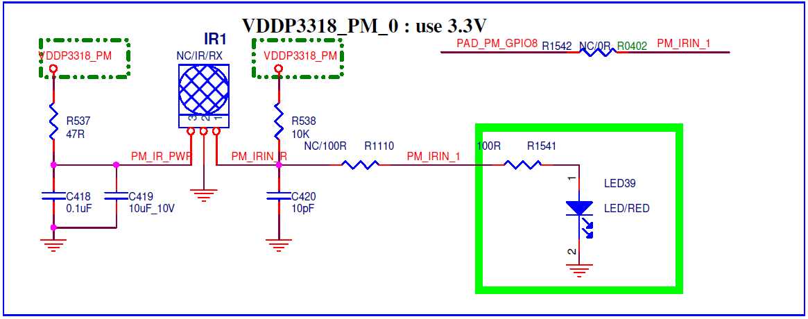
4. HARDWARE CONNECTION INTRODUCTION
Connect the infrared receiver to the development board according to the direction indicated in the schematic.
5. RISCV USAGE INTRODUCTION
5.1. Driver Path
sc/driver/sysdriver/ir/os/ir_os.h
sc/driver/sysdriver/ir/drv/pub/drv_ir.h
sc/driver/sysdriver/ir/drv/src/drv_ir.c
sc/driver/sysdriver/ir/drv/src/drv_ir_test.c
sc/driver/sysdriver/ir/hal/chipname/src/hal_ir.c
sc/driver/sysdriver/ir/hal/chipname/inc/hal_ir.h
sc/driver/sysdriver/ir/hal/chipname/inc/hal_ir_cfg.h
5.2. CONFIG Configuration
The config file is located at mak/options_chipname_riscv_isw.mak, enable CONFIG_IR_SUPPORT.
# Feature_Name = [DRV] IR driver support
# Description = IR driver support
# Option_Selection = TRUE, FALSE
CONFIG_IR_SUPPORT = TRUE
5.3. SYSDESC Configuration
The chipname_xxx.sys file is used to describe the hardware attributes of peripherals. The attribute values contained in the peripheral node can be used to configure the peripherals, similar to the Linux device tree. The file is located in sc/driver/sysdriver/sysdesc/hal/chipname/pub.
<ir0>
    [reg_u32_u16] 0x22CE200 0x200;
    [interrupts_u32_u32] INT_FIQ_IR_1 0xFFFF;
    [camclk_u32] CAMCLK_ir_nonpm0;
    [status_u8] 0;
| Attribute | Description | Setting value | Remark |
|---|---|---|---|
| reg_u32_u16 | Specify bank address | 0x22CE200 | Modification prohibited |
| interrupts_u32_u32 | Specify interrupt number | INT_FIQ_IR_1 | Modification prohibited |
| camclk_u32 | Specify clock source | CAMCLK_ir_nonpm0 | No modification required |
| status_u8 | Select whether to enable the driver | 1-enable; 0-disable | Can be modified as needed, the default is disable |
5.4. PADMUX Configuration
Method 1: CONFIG_PADMUX_SUPPORT=TRUE
If the chipname_xxx.sys file is configured with the attribute <padmux>, then the PADMUX setting is directly configured here:
    <padmux>
        [schematic_u32_u32_u32] PAD_GPIOC_00 PINMUX_FOR_IR0_IN_MODE_1 MDRV_PUSE_IR,
                                PAD_GPIOC_01 PINMUX_FOR_IR1_IN_MODE_1 MDRV_PUSE_IR1,
                                PAD_GPIOC_02 PINMUX_FOR_IR2_IN_MODE_1 MDRV_PUSE_IR2,
                                PAD_GPIOC_03 PINMUX_FOR_IR3_IN_MODE_1 MDRV_PUSE_IR3,
                                PAD_PM_GPIO2 PINMUX_FOR_PM_IR_IN_MODE_1 MDRV_PUSE_IR4;
        [status_u8] 1;
Otherwise, by enabling the PADMUX driver, configure the pin multiplexing function in the chipname-xxx-padmux.c file, which is located in sc/driver/sysdriver/padmux/hal/chipname/src. You only need to add the following content to the corresponding schematic attribute:
    pad_info_t schematic[] =
    {
        {PAD_GPIOC_00 PINMUX_FOR_IR0_IN_MODE_1 MDRV_PUSE_IR},
        {PAD_GPIOC_01 PINMUX_FOR_IR1_IN_MODE_1 MDRV_PUSE_IR1},
        {PAD_GPIOC_02 PINMUX_FOR_IR2_IN_MODE_1 MDRV_PUSE_IR2},
        {PAD_GPIOC_03 PINMUX_FOR_IR3_IN_MODE_1 MDRV_PUSE_IR3},
        {PAD_PM_GPIO2 PINMUX_FOR_PM_IR_IN_MODE_1 MDRV_PUSE_IR4},
    };
The first column is the pin index number, which can be queried in sc/drivers/sysdriver/gpio/hal/chipname/pub/gpio.h;
The second column is the mode definition, which can be queried in sc/drivers/sysdriver/gpio/hal/chipname/pub/padmux.h;
The third column is the index name of the pin and matching mode, which can be queried in sc/drivers/sysdriver/padmux/drv/pub/drv_puse.h.
5.5. Sample Code
The demo source code is located at sc/driver/sysdriver/ir/drv/src/drv_ir_test.c.
/* The callback function, which will be called when receiving IR signal */
u32 ir_get_value(u32 group)
{
    u64 data;
    u8  repeat;
    u32 addr;
    u32 cmd_code;
    u32 key_value;

    data = drv_ir_key_dequeue(group); //Get the IR signal analysis result
    if (data)
    {
        repeat    = data & 0x1;       //Repeat flag, 1: repeat occurs
        key_value = (u32)data >> 0x1;
        addr      = (key_value & 0xFFFF00) >> 8; // customer code
        cmd_code  = key_value & 0x00FF; // command code
        cliPrintf("ir%u addr: [0x%x] cmd_code: [0x%x], repeat [0x%x]\n", group, addr, cmd_code, repeat);
    }
    return data;
}

static int ir_ut_test(CLI_t *cli, char *p)
{
    u32 group;
    u32 decode_mode;
    u32 customer_code = 0x00FF;

    if ((CliTokenCount(cli) == 2) || (CliTokenCount(cli) == 3))
    {
        if (CliTokenPopNum(cli, &group, 0) != eCLI_PARSE_OK)
            goto ir_help_exit;

        if (CliTokenPopNum(cli, &decode_mode, 0) != eCLI_PARSE_OK)
            goto ir_help_exit;

        if (decode_mode == 1)
            if (CliTokenPopNum(cli, &customer_code, 0) != eCLI_PARSE_OK)
                goto ir_help_exit;

        /* Configure the decoding mode of the IR device, the customer code and the callback function for receiving the IR signal */
        if (drv_ir_config(group, decode_mode, customer_code, ir_get_value))
            return eCLI_PARSE_ERROR;
    }
    else
    {
    ir_help_exit:
        cliPrintf("command format : ir [group] [decode_mode:1] [customer code(16bit)]\n");
        cliPrintf("command format : ir [group] [decode_mode:2 or 3] \n");
        return -eCLI_PARSE_INVALID_PARAMETER;
    }

    return eCLI_PARSE_OK;
}
6. API Reference
The header file is located at sc/driver/sysdriver/ir/drv/pub/drv_ir.h.
| API Name | Function |
|---|---|
| drv_ir_config | Set the decoding mode of the IR device |
| drv_ir_key_dequeue | Get the customer code, command code, and repeat flag |
typedef u32 (*ir_decode)(u32);
extern u64 drv_ir_key_dequeue(u32 group);
extern int drv_ir_config(u32 group, u32 decode_mode, u32 customer_code, ir_decode ir_handle);
6.1 drv_ir_config
-
Purpose
Set the decoding mode of the IR device, the customer code and the callback function for receiving IR signals.
-
Syntax
int drv_ir_config(u32 group, u32 decode_mode, u32 customer_code, ir_decode ir_handle)
-
Parameter
Parameter name Value Description group 0 IR device number decode_mode 1: Full, 2: Raw, 3: RC5 Decoding mode customer_code 16-Bit customer code Only Full mode needs to be configured ir_handle Function pointer Used to respond to received IR signals -
Return value
Return value Description 0 Success -7 IR device not supported
6.2 drv_ir_key_dequeue
-
Purpose
Get the customer code, command code, and repeat flag after decoding the IR signal.
-
Syntax
u64 drv_ir_key_dequeue(u32 group)
-
Parameter
Parameter name Value Description group 0 IR device number -
Return value
Return value Description data BIT24-BIT9 is the customer code, BIT8-BIT1 is the command code, and BIT0 is the repeat flag
7. FAQ
7.1. IR Driver Cannot Receive IR Signal
-
Check whether padmux has been configured, see 5.4. PADMUX Configuration.
-
Check whether config is configured, see 5.2. CONFIG Configuration.
-
Check whether the
statusof the SYSDESC IR node isok. -
Check the remote control waveform to determine whether the IR_IN signal complies with the NEC and RC5 formats, and the current decoding mode matches the source signal.
-
Check whether there is a place in the IR Receiver in the hardware schematic that needs to be shorted or a resistor is added (such as R1110/R1542 in Figure 6-1).
Figure 6-1: IR Hardware Schematic