UART USER GUIDE
REVISION HISTORY
| Revision No. | Description |
Date |
|---|---|---|
| 1.0 | 04/18/2023 | |
| 1.1 | 04/08/2025 |
1. OVERVIEW
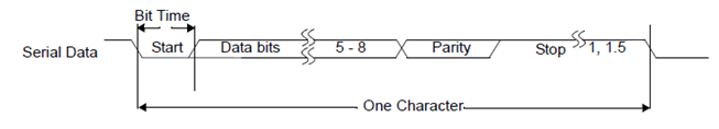
UART generally refers to a universal asynchronous communication transceiver, and its communication characteristics are asynchronous and serial. The UART bus has two data lines, TX and RX, to achieve full-duplex transmission and reception. The sender and receiver parse the received signal through their own set frame format and baud rate, so the sender and receiver are required to use the same frame format and baud rate during the communication process.
SigmaStar UART is a module that complies with the standard serial communication protocol. It contains multiple UARTs, among which there are different names of FUART and UART. The difference is that FUART has more CTS/RTS hardware flow control function than UART. All UARTs support DMA mode. UART0 is generally used as the console port by default.
2. Keyword Description
-
TX
Data transmission function/pin, sends UART signal according to the set frame format and baud rate.
-
RX
Data reception function/pin, the received signal will be parsed by UART according to the set frame format and baud rate, TX and RX share the same set of settings.
-
CTS
Flow control pin/signal, input signal, interpreted as "send permission". Used to determine whether data can be sent to the other party, low level is valid.
-
RTS
Flow control pin/signal, output signal, interpreted as "send request". Used to indicate that this device is ready to receive data, low level is valid.
-
FIFO mode
Each frame of data needs to be passed to the UART hardware send buffer register by the CPU, and then the UART takes it out of the send buffer and sends it out. The hardware send buffer is 32 bytes. Or when receiving, the CPU reads from the UART hardware receive buffer register, and the hardware receive buffer is 32 bytes.
-
DMA mode
Each frame of data no longer needs to be sent or read by the CPU one by one. It only needs to write the data to be sent to the storage location specified by DMA at one time before triggering communication, and then trigger communication; or take all the received data from the specified storage at one time; during the communication execution, the data interaction between UART is completed by URDMA itself, without the CPU participating. DMA mode can make the transmission more coherent, reduce the CPU loading, reduce the number of UART communication interrupts, and at the same time, the 4096-byte storage space provided for receiving and sending can greatly reduce the possibility of data loss.
-
URDMA
A module dedicated to providing data handling services for UART, which needs to be enabled in DMA mode. After enabling, UART will no longer be interrupted, and URDMA will be interrupted; and when DMA is enabled, the CPU can no longer access the UART register, otherwise it will cause a jam.
-
CONSOLE PORT
The console is a buffer concept, which is specially used for the kernel to print and busybox to receive shell commands. The PC is connected to the Console Port, and the terminal application of the PC is used to display print information or input operation instructions.
-
PADMUX
Pin multiplexing, connect UART PAD with actual pins, so that signals can be transmitted through pins.
-
DIGMUX
Used to connect UART TX/RX digital message with UART PAD. Different UART PADs can be connected to different UART modules. However, the PAD group PAD_PM_UART_TX and PAD_PM_UART_RX, which are used as CONSOLE PORT by default, cannot switch digmux.
For example: when the hardware layout is fixed, assuming that the function of UART1 is used originally, HW CTS/RTS support is needed, but FUART does not have the corresponding PADMUX to switch to this set of hardware pins. You can switch UART1 and FUART by switching DIGMUX. At this time, the TX/RX signal connection of FUART and the TX/RX signal connection of UART1 are interchanged, but CTS/RTS is still the pin set by FUART originally, which meets the use of HW CTS/RTS.
3. Functional Description
3.1. UART Resource
PCUPID provides 6 sets of standard UART, 4 sets of FUART (uart modules with hardware flow control, supporting CTS/RTS, namely fuart, uart1, uart2, uart3, flow control can be enabled by configuring sctp_enable in dts) and one set of PM_UART (DMA mode is not supported).
The correspondence between each UART/URDMA and bank address is as follows. UART is uniquely bound to URDMA, for example, FUART is bound to URDMA, and UART0 is bound to URDMA0:
| UART IP | FUART | UART0 | UART1 | UART2 | UART3 | UART4 | UART5 | UART6 | UART7 | UART8 | PM_UART |
|---|---|---|---|---|---|---|---|---|---|---|---|
| BANK ADDR | 1102 | 1108 | 1109 | 110A | 110B | 110C | 110D | 1140 | 1142 | 1144 | 0035 |
| URDMA IP | URDMA | URDMA0 | URDMA1 | URDMA2 | URDMA3 | URDMA4 | URDMA5 | URDMA6 | URDMA7 | URDMA8 |
|---|---|---|---|---|---|---|---|---|---|---|
| BANK ADDR | 1103 | 1107 | 110E | 110F | 1111 | 1112 | 1113 | 1141 | 1143 | 1145 |
3.2. Function Support
The following table provides the support status of each UART for each function.
| Function | FIFO mode | FIFO buffer size(byte) | DMA mode | DMA buffer size(byte) | HW CTS/RTS | baudrate | protocol |
|---|---|---|---|---|---|---|---|
| Support status | ✔ | 32 | ✔ (except for PM_UART) | 4096 | only fuart | ✔ | ✔ |
The baud rate support is as follows:
UART |
BAUDRATE(bps) |
|---|---|
| ALL UART | 1200 |
| ALL UART | 1800 |
| ALL UART | 2400 |
| ALL UART | 4800 |
| ALL UART | 9600 |
| ALL UART | 19200 |
| ALL UART | 38400 |
| ALL UART | 57600 |
| ALL UART | 115200 |
| ALL UART | 230400 |
| ALL UART | 460800 |
| ALL UART | 500000 |
| ALL UART | 576000 |
| ALL UART | 921600 |
| ALL UART | 1000000 |
| ALL UART | 1152000 |
| ALL UART | 1500000 |
| ALL UART | 2000000 |
| ALL UART | 2500000 |
| ALL UART | 3000000 |
| ALL UART | 3500000 |
The UART communication protocol support is as follows:
UART |
start bits | char bits | even parity | stop bits |
|---|---|---|---|---|
| ALL UART | 1 bit | 5 bits;6 bits; 7 bits; 8 bits | Y/N | 1 bit; 1.5 bits |
The communication sequence diagram is shown in Figure 3-1:
3.3. Notes
-
External pull-up
RX must be connected to an external pull-up, and TX is recommended to be connected to an external pull-up.
-
FIFO mode
When using FIFO mode, the HW buffer size is only 32 bytes. When UART cannot respond to the UART interrupt in time before the buffer is filled, and then read the data from the HW buffer, the received data will be lost.
3.4. Baud Rate Calculation
The baud rate refers to the modulation rate of the data signal on the carrier. It is expressed by the number of times the carrier modulation state changes per unit time and is an important indicator of UART. The actual baud rate output by the current hardware design UART is determined by the Clk source input to the UART and the set frequency division value. The relationship between the baud rate (BAUD), the frequency division value (DIV) and the input CLK frequency (CLK) is as follows:
DIV = CLK / (BAUD x 16)
Since the CLK rate given to the UART is not continuous, the baud rate (error 3%) that the UART can support is also not continuous according to the formula.
The modification of the baud rate.
It can be set in the user space application.
It can also be modified through the stty command. For example, to change the baud rate of UART1 to 115200:
stty -F /dev/sttyS1 ospeed 115200
4. Hardware Hookup
-
Standard UART refers to a UART communication method that does not contain any hardware flow control mechanism. It only relies on the start bit, data bit, parity bit (optional) and stop bit to define the data frame. Just use TX to connect to the other end RX, and RX to connect to the other end TX.
-
FUART refers to adding hardware or software flow control mechanism on the basis of standard UART to prevent data loss and improve communication reliability. On the basis of standard UART, add CTX to connect to the other end CTS, and CTS to connect to the other end RTS.
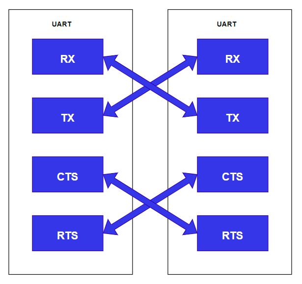
Figure 4-1: UART Connection
5. Uboot usage introduction
5.1. Uboot Config configuration
The configurations that need to be selected when compiling Uboot are as follows:
Device Drivers --->
    Serial drivers --->
        (1) UART used for console
        [*] Enable Driver Model for serial drivers
        [ ] Enable RX buffer for serial input
        [ ] Search for serial devices after default one failed
        [ ] Probe all available serial devices
5.2 Uboot DTS configuration
aliases {
    console = &uart0;
    serial0 = &uart0;
    serial1 = &uart1;
    serial2 = &fuart;
    serial3 = &uart2;
};

uart0: uart0@1F221000 {
    compatible = "sstar,uart";
    reg = <0x1F221000 0x100>;
    group = <0>;
    char-bits = <8>;
    stop-bits = <1>;
    parity-en = <0>; // 0-disable; 1-odd; 2-even.
    tolerance = <3>;
    status = "okay";
};

uart1: uart1@1F221200 {
    compatible = "sstar,uart";
    reg = <0x1F221200 0x200>;
    group = <1>;
    char-bits = <8>;
    stop-bits = <1>;
    parity-en = <0>; // 0-disable; 1-odd; 2-even.
    tolerance = <3>;
    status = "okay";
};
UART DTS configuration instructions:
Attribute DescriptionRemarks compatible Used to match the driver Modification prohibited reg IO_address Address_size Modification prohibited group UART group number No modification required rate Baud rate If you need to specify, you can add attributes to the node, or call the API to dynamically adjust during use char-bits Data bits If there is no such attribute, the default is 8 bits stop-bits Stop bits If there is no such attribute, the default is 1 bit parity-en Parity check If there is no such attribute, the default is no check 0: no parity 1: odd parity 2: even parity tolerance Baud rate tolerance percentage The number N represents N% If there is no such attribute, the default is 3% status Node enable, used to enable the UART "okay": enable "disabled": disable 5.3 Uboot cmd parameter description
Reference file:
cmd/sstar/uart.c
This provides uart test commands, which can be used to operate uart under the uboot command line. You must first init uart before you can use putchar to send data or getchar to receive data.
-
Initialize uart:
uart init [port] [baudrate]
Parameter name Description port uart serial number, corresponding to dts serial* serial number baudrate baud rate -
Send data:
uart putchar [char]
Parameter name Description char String to send -
Receive data:
uart getchars size
Parameter name Description size Get the number of data in Bytes
5.4 Uboot cmd usage example
SigmaStar # uart init 2 115200 // Get serial2, i.e. uart2 device
SigmaStar # uart putchar c // Send character 'c'
SigmaStar # uart getchar // Receive character
6. Kernel Usage Introduction
6.1. Kernel Config Configuration
To compile the SigmaStar UART driver into the kernel, you need to type make menuconfig in the command line to enter the kernel configuration interface, and then turn on the Serial / UART driver, which is turned on by default.
Device Drivers-->

    SStar SoC platform drivers-->

        [*] SSTAR UART driver
6.2 DTS definition
In pcupid.dtsi, the fuart0 and fuart node sections are as follows:
aliases {
    console = &fuart0;
    serial0 = &fuart0;
    serial1 = &fuart1;
    serial2 = &fuart2;
    serial3 = &uart3;
    serial4 = &uart4;
    serial5 = &uart5;
    serial6 = &uart6;
    serial7 = &uart7;
    serial8 = &uart8;
    serial9 = &fuart;
    serial10 = &pm_uart;
};

fuart0: fuart0@1F221000 {
        compatible = "sstar,uart";
        reg = <0x00 0x1F221000 0x00 0x100>, <0x00 0x1F220E00 0x00 0x100>;
        interrupts= <GIC_SPI INT_IRQ_FUART_0 IRQ_TYPE_LEVEL_HIGH>, <GIC_SPI INT_IRQ_UART0_MERGE IRQ_TYPE_LEVEL_HIGH>, <GIC_SPI INT_IRQ_UART0_MERGE IRQ_TYPE_LEVEL_HIGH>;
        //dma-enable;
        sctp_enable = <0>;
        rx_fifo_level = <0>;
        tx_fifo_level = <0>;
        digmux = <0>;
        clocks = <&CLK_fuart0>;
        status = "ok";
    };

fuart: fuart@1F220400 {
        compatible = "sstar,uart";
        reg = <0x00 0x1F220400 0x00 0x100>, <0x00 0x1F220600 0x00 0x100>;
        interrupts= <GIC_SPI INT_IRQ_FUART IRQ_TYPE_LEVEL_HIGH>, <GIC_SPI INT_IRQ_UART_MERGE IRQ_TYPE_LEVEL_HIGH>, <GIC_SPI INT_IRQ_UART_MERGE IRQ_TYPE_LEVEL_HIGH>;
        dma-enable;
        sctp_enable = <0>;
        rx_fifo_level = <0>;
        tx_fifo_level = <0>;
        digmux = <1>;
        clocks = <&CLK_fuart>;
        status = "ok";
    };
In the above paragraph, the uart alias defined by aliases, such as serial0, will eventually be registered as /dev/ttyS0, and bound one by one, such as /dev/ttyS9 is bound to FUART.
The description of the attributes in the node is as follows:
Attributes DescriptionRemarks compatible Used to match driver registration Modification prohibited reg IO_address Address_size No modification required interrupts UART interrupt number and interrupt type description A uart has 3 interrupts, in the following order: 1. UART TX/RX interrupt 2. URDMA TX/RX interrupt 3. UART shift register clear interrupt dma-enable Whether to use DMA mode Comments indicate not enabled sctp_enable HW CTS/RTS enable 1: enable 0: disable rx_fifo_level Receive interrupt water level setting FIFO mode takes effect; the level setting is as follows: 0: 1 character in FIFO 1: ¼ FIFO full 2: ½ FIFO full 3: FIFO 2 less than full tx_fifo_level Transmit interrupt level setting FIFO mode takes effect; the level setting is as follows: 0: FIFO empty 1: 2 characters in FIFO 2: ¼ FIFO full 3: ½ FIFO full digmux Used to swap pads between different uarts By default, no modification is required. If the pad of uart1 is used for uart2 and the pad of uart2 is used for uart1, you only need to swap the digmux values of uart1 and uart2. clocks Clock node Modification prohibited status Node enable, used to enable the UART "ok": enable "disabled": disable Note: pm_uart does not have digmux, and the digmux values of all uarts cannot be repeated.
6.3 PADMUX configuration
The padmux configuration method of UART/FUART in Uboot and Kernel environment is the same. You only need to configure the padmux.dtsi in the corresponding padmux according to the selected pin. The padmux of UART0 generally does not need to be configured. The following is an example of configuring FUART padmux.
<PAD_GPIOE_11 PINMUX_FOR_FUART_MODE_1 MDRV_PUSE_FUART_TX>,
<PAD_GPIOE_10 PINMUX_FOR_FUART_MODE_1 MDRV_PUSE_FUART_RX>,
<PAD_GPIOE_13 PINMUX_FOR_FUART_MODE_1 MDRV_PUSE_FUART_RTS>,
<PAD_GPIOE_12 PINMUX_FOR_FUART_MODE_1 MDRV_PUSE_FUART_CTS>,
The first column is the pin index number, which can be found in /drivers/sstar/inlcude/{chipname}/gpio.h;
The second column is the mode definition. In the m_hal_gpio_st_padmode_info_tbl array in /drivers/sstar/gpio/{chipname}/hal_pinmux.c, the multiplexing relationship of all pins is listed. To check which multiplexing functions the pin supports, you can query the array;
The third column is the index name of the pin and the matching mode, which can be found in /drivers/sstar/include/drv_puse.h.
6.4 Introduction to module usage
The basic process of using user space applications is as follows:
-
Open the device node
-
UART configuration
-
Read and write calls
For example: connect the serial port to the host PC and use the serial port tool to test sending and receiving data. Source code reference 6.5.Sample code chapter
/customer # echo 987654 > 1.txt
/customer # ./uart_ut -D /dev/ttyS1 -B 115200 -p 1.txt
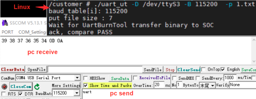
Figure 6-4 UART ut test6.5 Sample code
This demo provides reference for reading and writing UART operations, which can be changed according to needs. The configurable parameters are:
Attribute Description -D Used to specify the device node; such as "-D /dev/ttyS1" -B Used to specify the baud rate, such as "-B 9600" -C Used to enable flow control function -p Used to specify the data to be sent -g Used to specify that the received data is saved to a file #include <stdio.h> #include <stdlib.h> #include <unistd.h> #include <sys/types.h> #include <sys/stat.h> #include <fcntl.h> #include <errno.h> #include <sys/time.h> #include <time.h> #include <string.h> #include <sys/ioctl.h> #include <termios.h> #include <stdint.h> #include <assert.h> #include <netinet/in.h> #include <signal.h> #include <getopt.h> #define msleep(x) usleep(x * 1000) #define TX_SIZE 64 #define RX_SIZE 256 static char * device = "/dev/ttyS1"; static int options_flag; static speed_t speed; static char * put_file = NULL; static char * get_file = NULL; typedef unsigned int u32; #define TABLE_LEN 31 static const u32 baud_bits[TABLE_LEN] = {B4000000, B3500000, B3000000, B2500000, B2000000, B1500000, B1152000, B1000000, B921600, B576000, B500000, B460800, B230400, B115200, B57600, B38400, B19200, B9600, B4800, B2400, B1800, B1200, B600, B300, B200, B150, B134, B110, B75, B50, B0}; static const u32 baud_table[TABLE_LEN] = {4000000, 3500000, 3000000, 2500000, 2000000, 1500000, 1152000, 1000000, 921600, 576000, 500000, 460800, 230400, 115200, 57600, 38400, 19200, 9600, 4800, 2400, 1800, 1200, 600, 300, 200, 150, 134, 110, 75, 50, 0}; /* Print all baud rates */ void buad_help(void) { int i = 0; int j = 0; printf("support buad: \n"); for (i = 0; i < TABLE_LEN; i++) { j = (i + 1) % 8; if (j == 0) printf("\n"); printf(" %8d ", baud_table[i]); } printf("\n"); } /* ut supports commands */ static void print_usage(const char *prog) { printf("Usage: %s [-DBCpg]\n", prog); puts( " -D --device device to use (default /dev/ttyS1)\n" " -B --baud baud rate (bps)\n" " -C --flow flow Control\n" " -p --put_file put file \n" " -g --get_file get file\n"); exit(1); } /* Get the configured baud rate */ static int get_baud_rate(void) { int i = 0; for (i = 0; i < TABLE_LEN; i++) { if (speed == baud_table[i]) { printf("baud_table[i]: %d\n", baud_table[i]); return baud_bits[i]; } } buad_help(); return -1; } /* Open the uart node and configure uart */ int uart_open(char *name, int baud, int flag, int timeout_ms) { int fd; int ret; struct termios options; fd = open(name, flag); if (fd == -1) { printf("%s: open error\n", name); return -1; } ret = tcgetattr(fd, &options); if (-1 == ret) { return -1; } options.c_cflag &= ~CSIZE; options.c_cflag |= CS8; options.c_cflag |= CLOCAL | CREAD; options.c_cflag |= PARENB; options.c_iflag &= ~PARODD; options.c_iflag &= ~INPCK; options.c_cflag &= ~CSTOPB; options.c_lflag &= ~(ICANON | ECHO | ECHOE | ISIG); if (!timeout_ms) { options.c_cc[VMIN] = 1; options.c_cc[VTIME] = 0; } else { options.c_cc[VMIN] = 0; options.c_cc[VTIME] = timeout_ms / 100; } ret = cfsetispeed(&options, baud); if (ret) { printf("cfsetispeed err: %d\n", ret); } ret = cfsetospeed(&options, baud); if (ret) { printf("cfsetispeed err:%d \n", ret); } options.c_iflag &= ~(BRKINT | ICRNL | INPCK | ISTRIP | IXON); options.c_cflag |= options_flag; tcflush(fd, TCIFLUSH); ret = tcsetattr(fd, TCSANOW, &options); if (-1 == ret) { return -1; } return fd; } /* close */ static int uart_close(int fd) { return close(fd); } /* uart write */ static size_t uart_write(int fd, void *buf, size_t count) { size_t left_count = count; ssize_t real_count = 0; do { real_count = write(fd, buf, left_count); if (0 == real_count) { printf("write timeout !!!\n"); break; } if (0 > real_count) { printf("write fail !!!\n"); break; } buf += real_count; left_count -= real_count; } while (left_count); count -= left_count; return count; } /* uart read */ static size_t uart_read(int fd, void *buf, size_t count) { size_t left_count = count; ssize_t real_count = 0; do { real_count = read(fd, buf, left_count); if (0 == real_count) { break; } if (0 > real_count) { printf("read fail !!!\n"); break; } buf += real_count; left_count -= real_count; } while (left_count); count -= left_count; return count; } /* Parsing parameters */ static void parse_opts(int argc, char *argv[]) { int c; options_flag = 0; while (1) { static const struct option lopts[] = { {"device", 1, 0, 'D'}, {"baud", 1, 0, 'B'}, {"flow", 0, 0, 'C'}, {"put_file", 1, 0, 'p'}, {"get_file", 1, 0, 'g'}, {NULL, 0, 0, 0}, }; c = getopt_long(argc, argv, "D:B:Cp:g:", lopts, NULL); if (c == -1) break; switch (c) { case 'D': device = optarg; break; case 'B': speed = atoi(optarg); break; case 'C': options_flag |= CRTSCTS; break; case 'p': put_file = optarg; break; case 'g': get_file = optarg; break; default: print_usage(argv[0]); } } } int main(int argc, char **argv) { int fd = 0; int ret = 0; u32 baud = 0; long filesize = 0; FILE * stream = NULL; char * write_buffer = NULL; char * read_buffer = NULL; struct stat put_statbuf; char * ack_buf = "uart"; parse_opts(argc, argv); ret = get_baud_rate(); if (-1 == ret) { return -1; } else { baud = ret; } fd = uart_open(device, baud, O_RDWR | O_NOCTTY | O_SYNC, 3000); if (-1 == fd) { return -1; } if (put_file) { stat(put_file, &put_statbuf); filesize = put_statbuf.st_size; printf("put file size : %ld\n", filesize); write_buffer = malloc(filesize); if (!write_buffer) { printf("malloc write_buffer fail !!!\n"); goto out; } stream = fopen(put_file, "r"); if (!stream) { printf("fopen %s fail !!!\n", put_file); goto out; } fread(write_buffer, 1, filesize, stream); ret = uart_write(fd, write_buffer, filesize); if (filesize != ret) { printf("write %s fail !!!\n", put_file); goto out; } memset(write_buffer, 0, filesize); printf("Wait for UartBurnTool transfer binary to SOC\n"); uart_read(fd, write_buffer, strlen(ack_buf)); ret = strcmp(write_buffer, ack_buf); if (!ret) { printf("ack, compare PASS\n"); } else { printf("ng, compare FAIL\n"); } goto out; } if (get_file) { printf("get file test of 32KBytes ... \n"); read_buffer = malloc(0xA000); if (!read_buffer) { printf("malloc read_buffer fail !!!\n"); goto out; } stream = fopen(get_file, "w"); if (!stream) { printf("fopen %s fail !!!\n", get_file); goto out; } printf("Wait for UartBurnTool transfer binary to SOC\n"); filesize = uart_read(fd, read_buffer, 0x8000); while (0 != filesize) { fwrite(read_buffer, 1, filesize, stream); if (filesize == 0x8000) { break; } } printf("\r\n [fwrite done] \r\n"); // uart_write(tty_fd, read_buffer, 0x800); goto out; } out: if (write_buffer) { free(write_buffer); } if (read_buffer) { free(read_buffer); } if (stream) { fclose(stream); } if (fd) { uart_close(fd); } return 0; }7. FAQ
Q1: URDMA-Received data is segmented
-
To reproduce the uart2 tx and rx self-loop, execute the following command on the soc board:
stty -F /dev/ttyS2 speed 9600 -icanon -echo

cat /dev/ttyS2 &

echo "0123456789101112" > /dev/ttyS2
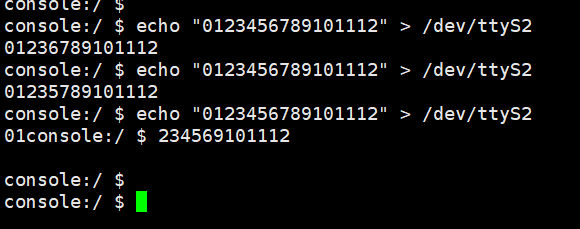
Figure 7-1 UART rx not continuousCause Analysis
DMA rx interrupt mechanism:
1 When the amount of data in the rx buff reaches the threshold setting, an interrupt is triggered and the data in the buff is moved away;
2 When the time for rx to wait for the amount of data to reach the threshold times out, an interrupt is also triggered to move the data in the buff away.
From the analysis experiment, we can see that the total amount of data sent is not large, far below the preset 0x500 threshold. In other words, the interrupt triggered in the second step is too fast, resulting in a batch of data being divided into two segments and sent to the tty layer.
Solution
The data is segmented because the rx timeout time is less than the baud rate code element transmission interval. Therefore, different rx timeout times should be set at different baud rates so that rx timeout value > symbol transmission interval
Formula:
cycle_time (clock unit) = 1/clk_mcu * 1000000000 ns
urdma timeout value: = N
Then:
t1 = cycle_time * 2 ^ N: rx wait timeout

t2 = 1000000000 / request_baud * 10(bits) Time to transmit a symbol
By adjusting the urdma rx timeout register (setting N), as long as t1 > t2 is satisfied, the segmentation problem can be solved.
Q2: Received data lost
-
The data received by UART is different from the data sent to UART. There are two cases: 1. The lost data is regular, only 0x11 and 0x13 are lost and 0x0A becomes 0x0D; 2. The lost data is irregular. In the first case, you only need to add options.c_iflag &= ~(ICRNL | IXON) when initializing the serial port;
-
The second case of UART RX received data loss is that the Received Data Available interrupt sent by UART is not processed by the CPU in time. There are two cases that will cause the UART interrupt not to be processed in time:
1 When UART interrupts, other interrupts are being processed. Because Linux does not have an interrupt preemption mechanism, the UART interrupt will be processed with a delay;
2 When UART interrupts, Linux interrupts are turned off (spin_lock_irqsave, etc.), so the UART interrupt will also be processed with a delay. Generally, the second case causes the loss of RX received data. Only when the baud rate is very high will the first case cause UART RX data loss. It can be determined by pulling the selected GPIO at the entrance of UART interrupt and Linux interrupt processing, and using LA to capture UARTRX and selected GPIO waveforms. The waveform of normal situation is shown in Figure 7-2. It can be seen that when the RX pin receives a Byte of data, it will wake up the RX interrupt once to take the data in the FIFO. The error situation is shown in Figure 7-3. At this time, the RX interrupt is woken up once after an interval of 16MS. The length of our hardware RX FIFO is 32Byte. Under the typical 115200 baud rate, data is continuously received. As long as the 2.78ms interrupt is not processed, data will be lost because the FIFO is full. Therefore, as long as there is a shutdown interrupt for more than 2.78ms in the system, it will theoretically cause UART reception to lose data.
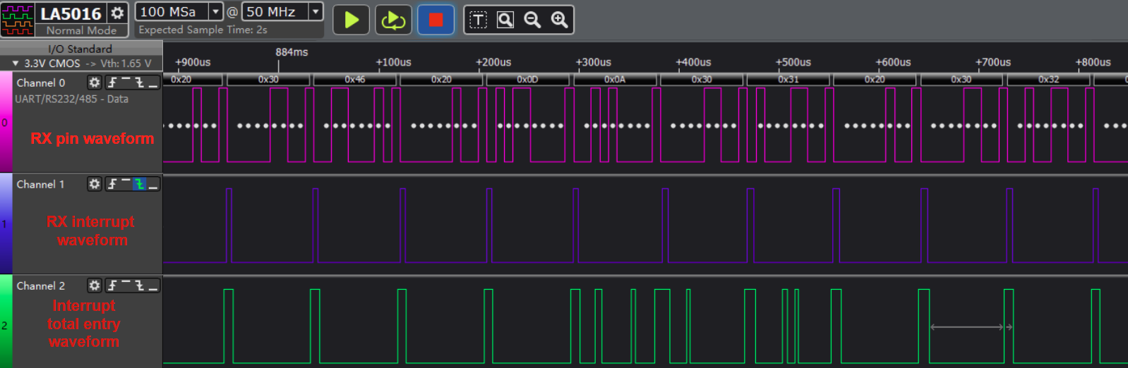
Figure 7-2 UART no data loss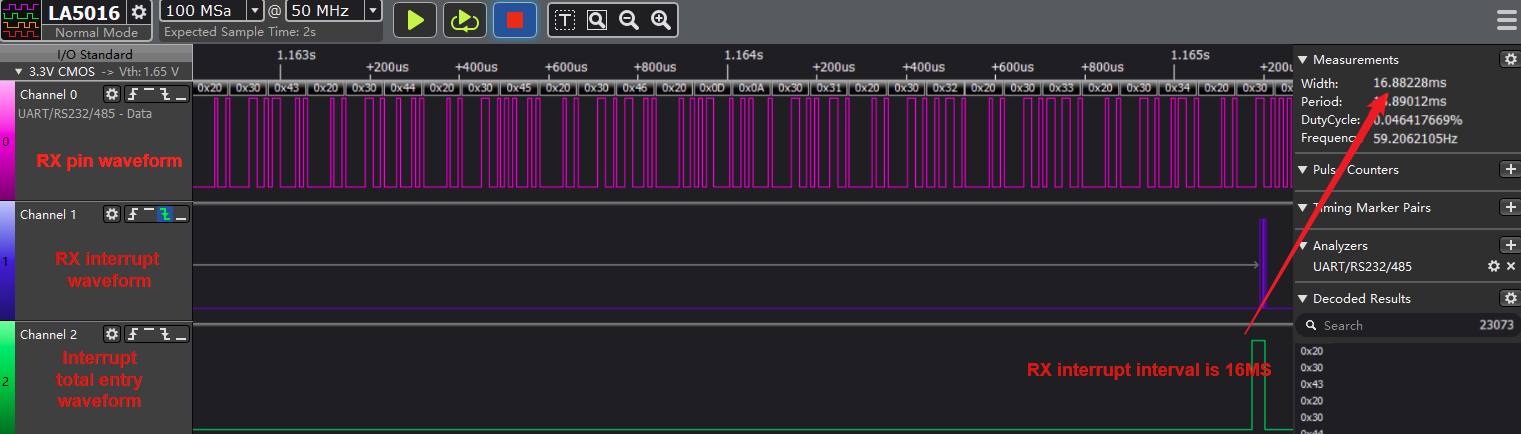
Figure 7-3 UART data lossCalculation method:
In the case of 8N1 protocol, 8 data bits, 1 stop bit, 1 start bit, no check bit, that is, 1 byte of communication data needs to occupy 10 bits of bit width.
Baud rate-concept: the rate of serial communication, unit bps (bits per second), that is, the number of binary bits that can be transmitted per second.
For example, 115200 means that 115200 binary bits can be transmitted per second, that is, 115200 bits
At a baud rate of 115200, the depth of 32-byte fifo, the calculation of waiting time:
time = (fifo depth * bit width occupied by each byte) / baud rate

= (32 * 10) / (115200) S

= 2.78ms
Solution
If the UART baud rate where data loss occurs is very high, processing other interrupts at this time may also cause the UART RX interrupt to be blocked for too long, resulting in data loss. At this time, turning on urdma can ensure that data will not be lost.
Q3: stty fails to set baud rate greater than 1M
-
Setting baud rate greater than 1M using stty command fails
/ # stty -F /dev/ttyS2 1000000

stty: invalid argument '1000000'
-
Description
Busybox issue. Baud rate greater than 1M can be set after busybox version 1.26.x.
-
Solution
If you need to set baud rate greater than 1M, you can use C PROGRAM to set it.
-