RISCV_UART USER GUIDE
REVISION HISTORY
| Revision No. | Description |
Date |
|---|---|---|
| 1.0 | 04/18/2023 | |
| 1.1 | 04/09/2025 |
1. OVERVIEW
UART generally refers to a universal asynchronous communication transceiver, and its communication characteristics are asynchronous and serial. The UART bus has two data lines, TX and RX, to achieve full-duplex transmission and reception. The sender and receiver parse the received signal through their own set frame format and baud rate, so the sender and receiver are required to use the same frame format and baud rate during the communication process.
SigmaStar UART is a module that complies with the standard serial communication protocol. It contains multiple UARTs, among which there are different names of FUART and UART. The difference is that FUART has more CTS/RTS hardware flow control function than UART. Generally, UART0 is used as the console port by default. This article describes how to use the Sigmastar UART driver under riscv.
2. Keyword Description
-
TX
Data transmission function/pin, sends UART signal according to the set frame format and baud rate.
-
RX
Data reception function/pin, the received signal will be parsed by UART according to the set frame format and baud rate, TX and RX share the same set of settings.
-
CTS
Flow control pin/signal, input signal, interpreted as "send permission". Used to determine whether data can be sent to the other party, low level is valid.
-
RTS
Flow control pin/signal, output signal, interpreted as "send request". Used to indicate that this device is ready to receive data, low level is valid.
-
FIFO mode
Each frame of data needs to be passed to the UART hardware send buffer register by the CPU, and then the UART takes it out of the send buffer and sends it out. The hardware send buffer is 32 bytes. Or when receiving, the CPU reads from the UART hardware receive buffer register, and the hardware receive buffer is 32 bytes.
-
DMA mode
Each frame of data no longer needs to be sent or read by the CPU one by one. It only needs to write the data to be sent to the storage location specified by DMA at one time before triggering communication, and then trigger communication; or take all the received data from the specified storage at one time; during the communication execution, the data interaction between UART is completed by URDMA itself, without the CPU participating. DMA mode can make the transmission more coherent, reduce the CPU loading, reduce the number of UART communication interrupts, and at the same time, the 4096-byte storage space provided for receiving and sending can greatly reduce the possibility of data loss.
-
URDMA
A module dedicated to providing data handling services for UART, which needs to be enabled in DMA mode. After enabling, UART will no longer be interrupted, and URDMA will be interrupted; and when DMA is enabled, the CPU can no longer access the UART register, otherwise it will cause a jam.
-
CONSOLE PORT
The console is a buffer concept, which is specially used for the kernel to print and busybox to receive shell commands. The PC is connected to the Console Port, and the terminal application of the PC is used to display print information or input operation instructions.
-
PADMUX
Pin multiplexing, connect UART PAD with actual pins, so that signals can be transmitted through pins.
-
DIGMUX
Used to connect UART TX/RX digital message with UART PAD. Different UART PADs can be connected to different UART modules. However, the PAD group PAD_PM_UART_TX and PAD_PM_UART_RX, which are used as CONSOLE PORT by default, cannot switch digmux.
For example, when the hardware layout is fixed, assuming that the function of UART1 is originally used, HW CTS/RTS support is required at this time, and fuart does not have the corresponding PADMUX to switch to this group of hardware pins. You can switch UART1 and FUART by switching DIGMUX. At this time, the TX/RX signal connection of FUART and the TX/RX signal connection of UART1 are interchanged, but CTS/RTS is still the pin originally set by FUART, which meets the use of HW CTS/RTS.
3. Functional Description
3.1. UART Resource
PCUPID provides 6 sets of standard UART, 4 sets of FUART (uart modules with hardware flow control, supporting CTS/RTS, namely fuart, uart1, uart2, uart3, flow control can be enabled by configuring sctpen_u8 in SYSDESC) and one set of PM_UART (DMA mode is not supported).
The correspondence between each UART/URDMA and bank address is as follows. UART is uniquely bound to URDMA, for example, FUART is bound to URDMA, and UART0 is bound to URDMA0:
| UART IP | FUART | UART0 | UART1 | UART2 | UART3 | UART4 | UART5 | UART6 | UART7 | UART8 | PM_UART |
|---|---|---|---|---|---|---|---|---|---|---|---|
| BANK ADDR | 1102 | 1108 | 1109 | 110A | 110B | 110C | 110D | 1140 | 1142 | 1144 | 0035 |
| URDMA IP | URDMA | URDMA0 | URDMA1 | URDMA2 | URDMA3 | URDMA4 | URDMA5 | URDMA6 | URDMA7 | URDMA8 |
|---|---|---|---|---|---|---|---|---|---|---|
| BANK ADDR | 1103 | 1107 | 110E | 110F | 1111 | 1112 | 1113 | 1141 | 1143 | 1145 |
3.2. Function Support
The following table provides the support status of each UART for each function.
| Function | FIFO mode | FIFO buffer size(byte) | DMA mode | DMA buffer size(byte) | HW CTS/RTS | baudrate | protocol |
|---|---|---|---|---|---|---|---|
| Support status | ✔ | 32 | ✔ (except for PM_UART) | 4096 | only fuart | ✔ | ✔ |
The baud rate support is as follows:
UART |
BAUDRATE(bps) |
|---|---|
| ALL UART | 1200 |
| ALL UART | 1800 |
| ALL UART | 2400 |
| ALL UART | 4800 |
| ALL UART | 9600 |
| ALL UART | 19200 |
| ALL UART | 38400 |
| ALL UART | 57600 |
| ALL UART | 115200 |
| ALL UART | 230400 |
| ALL UART | 460800 |
| ALL UART | 500000 |
| ALL UART | 576000 |
| ALL UART | 921600 |
| ALL UART | 1000000 |
| ALL UART | 1152000 |
| ALL UART | 1500000 |
| ALL UART | 2000000 |
| ALL UART | 2500000 |
| ALL UART | 3000000 |
| ALL UART | 3500000 |
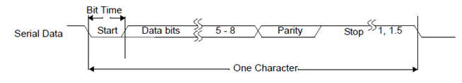
The UART communication protocol support is as follows:
UART |
start bits | char bits | even parity | stop bits |
|---|---|---|---|---|
| ALL UART | 1 bit | 5 bits;6 bits; 7 bits; 8 bits | Y/N | 1 bit; 1.5 bits |
The communication sequence diagram is shown in Figure 3-1:
3.3. Notes
-
External pull-up
RX must be connected to an external pull-up, and TX is recommended to be connected to an external pull-up.
-
FIFO mode
When using FIFO mode, the HW buffer size is only 32 bytes. When UART cannot respond to the UART interrupt in time before the buffer is filled, and then read the data from the HW buffer, the received data will be lost.
3.4. Baud Rate Calculation
The baud rate refers to the modulation rate of the data signal on the carrier. It is expressed by the number of times the carrier modulation state changes per unit time and is an important indicator of UART. The actual baud rate output by the current hardware design UART is determined by the Clk source input to the UART and the set frequency division value. The relationship between the baud rate (BAUD), the frequency division value (DIV) and the input CLK frequency (CLK) is as follows:
DIV = CLK / (BAUD x 16)
Since the CLK rate given to the UART is not continuous, the baud rate (error 3%) that the UART can support is also not continuous according to the formula.
The modification of the baud rate.
It can be set in the test program. The setting method refers to the test demo picture below.
4. HARDWARE CONNECTION INTRODUCTION
-
Standard UART refers to a UART communication method that does not contain any hardware flow control mechanism. It only relies on the start bit, data bit, parity bit (optional) and stop bit to define the data frame. Just use TX to connect to the other end RX, and RX to connect to the other end TX.
-
FUART (flow control UART) refers to adding hardware or software flow control mechanism on the basis of standard UART to prevent data loss and improve communication reliability. On the basis of standard UART, add CTX to connect to the other end CTS, and CTS to connect to the other end RTS.

Figure 4-1: UART Connection
5. RISCV USAGE INTRODUCTION
When testing UART communication, the following basic steps need to be ensured:
-
Hardware device connection, external pull-up resistor confirmation, a simple test method is to short-circuit tx and rx;
-
CONFIG supports UART driver, enabled by default;
-
SYSDESC file configures attributes required;
-
PADMUX settings;
-
API calls to execute communication.
5.1. DRIVER PATH
sc/driver/sysdriver/uart/drv/pub/drv_uart.h
sc/driver/sysdriver/uart/drv/src/drv_uart.c
sc/driver/sysdriver/uart/drv/src/drv_uart_test.c
sc/driver/sysdriver/uart/drv/src/drv_uart_lite.c
sc/driver/sysdriver/uart/hal/pcupid/src/hal_uart.c
sc/driver/sysdriver/uart/hal/pcupid/inc/hal_uart.h
sc/driver/sysdriver/uart/hal/pcupid/inc/hal_uart_cfg.h
5.2. CONFIG Configuration
The UART driver compilation option is enabled by default in RISCV. The config file is located at
mak/options_chipname_riscv_isw.mak, andCONFIG_UART_SUPPORTis enabled.CONFIG_UART_SUPPORT = TRUE
5.3. SYSDESC Configuration
The chipname-default.sys file is located in
sc/driver/sysdriver/sysdesc/hal/chipname/pub. Take fuart as an example, the node content is as follows:<fuart> [reg_u32] 0x2220400, 0x2220600; [interrupts_u32] INT_IRQ_FUART, INT_IRQ_UART_MERGE, INT_IRQ_UART_MERGE; [camclk_u16] CAMCLK_fuart; [rx_fifo_level_u8] 0; [tx_fifo_level_u8] 0; [sctpen_u8] 0; [dma_u8] 0; [digmux_u8] 1; [status_u8] 1;The description of the attributes in the node is as follows:
Attribute value Description Remark reg_u32 Used to specify the bank and range where UART (and URDMA) is located No modification required interrupts_u32 Specify the interrupt and trigger mode of UART (and URDMA) No modification required camclk_u16 Specify the clock source of UART No modification required dma_u8 Enable DMA function of FUART Write to 1 when needed sctpen_u8 HW CTS/RTS enable 1: enable 0: disable digmux_u8 Select which digmux the rx tx pin is connected to. Each uart will be connected to the corresponding digmux by default. If there is no special requirement, there is no need to set this attribute; 0xFF means that the driver will not modify the default digmux of the uart Modify as needed, if there is no special requirement, it is recommended to delete this attribute rx_fifo_level_u8 Select the level of uart rx fifo, which affects how many bytes are received to trigger an interrupt, and timeout will also trigger an interrupt. The current fifo depth is 32bytes;
"0" - 1 character in the FIFO;
"1" - FIFO ¼ full;
"2" - FIFO ½ full;
"3" - FIFO 2 less than fullModify as needed, if there is no special requirement, this attribute can be deleted. The default initial value of the driver is 0; it is only effective when the dma attribute is set to 0 tx_fifo_level_u8 Select the level of the uart tx fifo, which affects how many bytes are left in the txfifo to trigger an interrupt. Timeout will also trigger an interrupt. The current fifo depth is 32 bytes;
"0" - FIFO empty;
"1" - 2 characters in the FIFO;
"2" - FIFO ¼ full;
"3" - FIFO ½ full;Modify as needed, if there is no special requirement, this attribute can be deleted. The default initial value of the driver is 0; it is only effective when the dma attribute is set to 0 Status_u8 Select whether to enable the UART driver Modify as needed 5.4. PADMUX Setting
CONFIG configuration: CONFIG_PADMUX_SUPPORT=Y
If the
chipname-default.sysfile is configured with the attribute<padmux>, then the PADMUX setting is directly configured here, for example, fuart mode2:<padmux> [schematic_u32_u32_u32] PAD_GPIOC_02 PINMUX_FOR_FUART_MODE_2 MDRV_PUSE_FUART_RX, PAD_GPIOC_03 PINMUX_FOR_FUART_MODE_2 MDRV_PUSE_FUART_TX, PAD_GPIOC_04 PINMUX_FOR_FUART_MODE_2 MDRV_PUSE_FUART_CTS, PAD_GPIOC_05 PINMUX_FOR_FUART_MODE_2 MDRV_PUSE_FUART_RTS; [status_u8] 1;Otherwise, enable the PADMUX driver and configure the pin multiplexing function in the
chipname-xxx-padmux.cfile, which is located insc/driver/sysdriver/padmux/hal/chipname/src. You only need to add the following content to the correspondingschematicattribute:pad_info_t schematic[] = { {PAD_GPIOC_02 PINMUX_FOR_FUART_MODE_2 MDRV_PUSE_FUART_RX}, {PAD_GPIOC_03 PINMUX_FOR_FUART_MODE_2 MDRV_PUSE_FUART_TX}, {PAD_GPIOC_04 PINMUX_FOR_FUART_MODE_2 MDRV_PUSE_FUART_CTS}, {PAD_GPIOC_05 PINMUX_FOR_FUART_MODE_2 MDRV_PUSE_FUART_RTS}, };The first column is the pin index number, which can be queried in
sc/drivers/sysdriver/gpio/hal/chipname/pub/gpio.h;The second column is the mode definition, which can be queried in
sc/drivers/sysdriver/gpio/hal/chipname/pub/padmux.h;The third column is the index name of the pin and matching mode, which can be queried in
sc/drivers/sysdriver/padmux/drv/pub/drv_puse.h;5.5 Sample code
Demo source code reference: sc/driver/sysdriver/uart/drv/src/drv_uart_test.c
static int uart_ut_test(CLI_t * cli, char * p)
{
    uart_handle handle;
    uart_cfg cfg = {0};
    u8 *read_buf = NULL;
    u8 *write_buf = NULL;
    u32 read_len = 0;
    u32 read_len_left = 0;
    u32 i = 0;
    u8   argc;
    char *uart_name;

    argc = CliTokenCount(cli);

    if (argc < 1)
        return eCLI_PARSE_INPUT_ERROR;
    //uart test device
    uart_name = CliTokenPop(cli);

    cfg.rate = 115200;
    cfg.bit_length = 8;
    cfg.parity = UART_PARITY_NONE;
    cfg.stop = UART_STOP_1BIT;

    CamOsPrintf("start test %s...\n", uart_name);

    read_buf = CamOsMemAlloc(UART_BUF_SIZE);
    if (read_buf == NULL)
    {
        CamOsPrintf("alloc read buf fail.\n");
        return eCLI_PARSE_ERROR;
    }
    write_buf = CamOsMemAlloc(UART_BUF_SIZE);
    if (write_buf == NULL)
    {
        CamOsPrintf("alloc write buf fail.\n");
        return eCLI_PARSE_ERROR;
    }

    for (i = 0; i < UART_BUF_SIZE; i++)
    {
        *(write_buf + i) = i + 0x40;
        *(read_buf + i ) = 0;
    }
#if 1
    handle = drv_uart_open(uart_name);

    if (!handle)
        CamOsPrintf("drv_uart_open fail\n");
    //set attribute
    drv_uart_ioctrl(handle, UART_CMD_CONFIG, (void *)&cfg);
    //uart write
    drv_uart_write(handle, (u8 *)write_buf, UART_BUF_SIZE, -1);

    read_len_left = UART_BUF_SIZE;
    while (read_len < UART_BUF_SIZE)
    {
        read_len += drv_uart_read(handle, (read_buf + read_len), read_len_left, 0);
        read_len_left = UART_BUF_SIZE - read_len;
    }

    for (i = 0; i < UART_BUF_SIZE; i++)
    {
        if (*(write_buf + i) != *(read_buf + i))
        {
            CamOsPrintf("data check fail index %d.\n", i);
            break;
        }
    }
    drv_uart_close(handle);

#else

    handle = drv_uart_open(uart_name);

    if (!handle)
        CamOsPrintf("drv_uart_open fail\n");

    drv_uart_ioctrl(handle, UART_CMD_CONFIG, (void *)&cfg);

    drv_uart_write(handle, (u8 *)debug_char, 28, -1);

    do
    {
        read_len = drv_uart_read(handle, read_buf, 28, -1);

        if (read_len >= 0)
        {
            read_buf[read_len] = '\0';

            CamOsPrintf("%s", read_buf);

            if (read_buf[0] == 'q')
                break;
        }
        read_len_left += read_len;
    } while(1);

    drv_uart_close(handle);
#endif

    return eCLI_PARSE_OK;
}
6. API reference
-
The header file is located in
sc/driver/sysdriver/uart/drv/pub/drv_uart.htypedef struct { u8 bit_length; ///< length in number of bits u8 parity; ///< parity u8 stop; ///< stop bit u8 rtscts; u32 rate; ///< bit rate } uart_cfg; -
This function module provides the following interfaces:
API name Function drv_uart_open Used to open the uart device, which will perform initialization operations drv_uart_close Close the open uart. drv_uart_ioctrl Set the uart communication protocol. drv_uart_write Uart sends data to the obtained handle. drv_uart_read Uart receives data from the obtained handle.
6.1 drv_uart_open
-
Function
Used to open the uart device, which will perform initialization operations
-
Syntax
uart_handle drv_uart_open(char *name)
-
Parameters
Parameter name Description name uart device name
uart0: uart0
uart1: uart1
fuart: fuart -
Return Value
Result Description Non-NULL Successful NULL Failed
6.2 drv_uart_close
-
Function
Close the open uart
-
Syntax
void drv_uart_close(uart_handle handle)
-
Parameters
Parameter name Description handle Handle returned by open Successfully -
Return Value
none
6.3 drv_uart_ioctrl
-
Function
Set the uart communication protocol.
-
Syntax
s32 drv_uart_ioctrl(uart_handle handle, u32 cmd, void *arg)
-
Parameter
Parameter name Description handle uart handle, Successfully obtained by open cmd command, set protocol using UART_CMD_CONFIG arg protocol content -
Return Value
result Description 0 Successful -1 Failed
6.4 drv_uart_write
-
Function
Uart sends data to the obtained handle.
-
Syntax
s32 drv_uart_write(uart_handle handle, u8 *buf, u32 len, s32 timeout_ms)
-
Parameters
Parameter name Description handle uart handle, Successfully obtained by open buf send data buffer len send bytes timeout_ms blocking waiting time
= 0: non-blocking
< 0: blocking until completion
> 0: blocking set time -
Return Value
Result Description 0 uart is not enabled -1 error handle >0 completed bytes
6.5 drv_uart_read
-
Function
Uart receives data from the obtained handle.
-
Syntax
s32 drv_uart_read(uart_handle handle, u8 *buf, u32 len, s32 timeout_ms)
-
Parameters
Parameter name Description handle uart handle, Successfully obtained by open buf Receive data buffer len Number of received bytes timeout_ms Block waiting time
= 0: non-blocking
< 0: block until completion
> 0: block for a set time -
Return Value
Result Description 0 uart not enabled -1 error handle >0 Number of bytes completed
7. FAQ
When communication anomalies occur, you can refer to the following aspects for problem debugging. Several common troubleshooting directions are provided. In addition, it is recommended to capture waveforms for easy analysis during the debugging process. The debug method will be continuously updated later.
Troubleshooting direction Common problemsRemarks Padmux 1. Blocking mode, stuck in loop reading, console stuck and not moving; 2. No waveform, can't be triggered Refer to the PADMUX chapter, or padmux module description Communication baud rate UART is in busy state, baud rate cannot be set The client device keeps sending data to UART RX Clock source No waveform Refer to CLKGEN module description Interrupt RX data loss When UART interrupts, Linux interrupts are disabled (spin_lock_irqsave, etc.). You can use LA to capture the waveform for analysis -