RISCV_BSP_MOUNRIVER USER GUIDE
1. OVERVIEW
RISCV development environment is based on MounRiver Studio. Please refer to the RISCV development environment user guide to install the development environment and SDK template.
2. GPIO USAGE
2.1. Configuration
Sysdecs configuration:
Using gpio, you can configure gpio padmux through sysdecs. Configure PAD_PWM_OUT00-01 to gpio mode as follows.
sc\driver\sysdriver\sysdesc\hal\pcupid\pub\pcupid-default.sys:
<padmux>
    [schematic_u32_u32_u32]
        PAD_UART0_RX PINMUX_FOR_PM_FUART_MODE_3 MDRV_PUSE_PM_UART_RX,
        PAD_UART0_TX PINMUX_FOR_PM_FUART_MODE_3 MDRV_PUSE_PM_UART_TX,
        PAD_PWM_OUT00 PINMUX_FOR_GPIO_MODE MDRV_PUSE_NA,
        PAD_PWM_OUT01 PINMUX_FOR_GPIO_MODE MDRV_PUSE_NA;
    [status_u8] 1;
2.2. Test Demo Usage
1) Open the gpio test demo macro definition: __VER_GPIO__
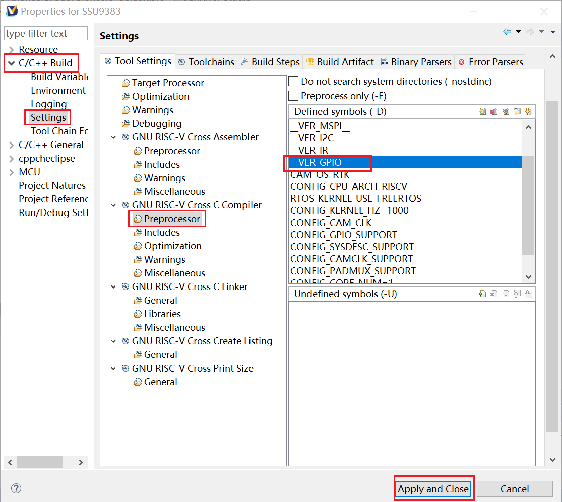
Figure 2-1: RISCV-1
2) Test demo path
sc/driver/sysdriver/gpio/drv/pub/drv_gpio.h

sc/driver/sysdriver/gpio/drv/src/gpio_test.c
3) Test command
Compile and burn riscv firmware according to the above configuration. Connect the riscv serial port and use the following command line for testing:
The pin name and the corresponding gpioNum can be viewed in sc/driver/sysdriver/gpio/hal/pcupid/pub/gpio.h.
gpio output [gpioNum] [level] //Set gpio output high and low levels
[gpioNum]: gpio number, 0-142
[level]: output level, 0: low level; 1: high level

gpio input/get [gpioNum] //Set gpio input, print level
[gpioNum]: gpio number, 0-142

gpio toggle [gpioNum] //Reverse gpio level
[gpioNum]: gpio number, 0-142

gpio state [gpioNum] //Get a single gpio input and output status
[gpioNum]: gpio number, 0-142

gpio list [num_of_pins] //Get a certain number of gpio input and output status
[num_of_pins]: gpio number, 0-142

gpio isr [gpioNum] [edge] //Enable gpio interrupt
[gpioNum]: gpio number, 0-142
[edge]: gpio interrupt type, 0: falling edge; 1: rising edge; 2: both edges; 3: low level; 4: high level;

gpio isrfree [gpioNum] //Disable gpio interrupt
[gpioNum]: gpio number, 0-142
2.3. GPIO Development
Refer to RISCV_GPIO USER GUIDE.
3. ADC USAGE
3.1. ADCLP (10bit)
3.1.1 Sysdecs Configuration
To use adclp, you need to open the adclp node through sysdecs configuration (no need to configure padmux). Taking adclp0 as an example, change status_u8 to 1.
sc\driver\sysdriver\sysdesc\hal\pcupid\pub\pcupid-default.sys:
<adclp0>
    [reg_u32] 0x2002800;
    [interrupts_u32] INT_PM_IRQ_SAR_KP;
    [camclk_u16] CAMCLK_sar;
    [interrupts_en_u8] 1;
    [ref_vol_u32] 1800;
    [upper_bound_u16] 0x3FF;
    [lower_bound_u16] 0;
    [status_u8] 1;
3.1.2 Test Demo Usage
1) Open the adclp test demo macro definition: __VER_ADCLP__
2) Test demo path
sc/driver/sysdriver/saradc/drv/pub/drv_adclp.h

sc/driver/sysdriver/saradc/drv/src/drv_adclp_test.c
3) Test command
Compile and burn the riscv firmware according to the above configuration. Connect the riscv serial port and use the following command line for testing:
adclp init [channel] //Initialize the specified adclp channel
[channel]: sampling channel, optional 0~4

adclp single [channel] //Get the sampling results of the specified channel
[channel]: sampling channel, optional 0~4

adclp scan //Get the sampling results of all channels
3.2. ADCMP (12bit)
3.2.1 Sysdecs Configuration
To use adcmp, you need to open the adcmp node through sysdecs configuration and configure padmux. Take adcmp0 as an example, change status_u8 to 1.
sc\driver\sysdriver\sysdesc\hal\pcupid\pub\pcupid-default.sys:
<adcmp0>
    [reg_u32] 0x200AC00, 0x200AE00, 0x2003C00, 0x2204600;
    [interrupts_u32] INT_PM_FIQ_ADCMP;
    [camclk_u16] CAMCLK_pm_pwm_adc;
    [dma_en_u8] 0;
    [dma_count_u32] 50;
    [clk_level_u8] 0;
    [ref_vol_u32] 1800;
    [regular_ch_u8] 0, 1, 2, 3, 4, 5, 6, 7, 8, 9, 10, 11;
    [inject_ch_u8] 12, 13, 14, 15, 16, 17, 18, 19, 20, 21;
    [external_res_u32] 0, 0, 0, 0, 0, 0, 0, 0, 0, 0, 0, 0, 0, 0, 0, 0, 0, 0, 0, 0, 0, 0;
    [upper_bound_u16] 0xFFFF, 0xFFFF, 0xFFFF, 0xFFFF, 0xFFFF, 0xFFFF, 0xFFFF, 0xFFFF, 0xFFFF, 0xFFFF, 0xFFFF,
                    0xFFFF, 0xFFFF, 0xFFFF, 0xFFFF, 0xFFFF, 0xFFFF, 0xFFFF, 0xFFFF, 0xFFFF, 0xFFFF, 0xFFFF;
    [lower_bound_u16] 0, 0, 0, 0, 0, 0, 0, 0, 0, 0, 0, 0, 0, 0, 0, 0, 0, 0, 0, 0, 0, 0;
    [status_u8] 1;

<padmux>
    [schematic_u32_u32_u32]
        PAD_SAR_ADC0_00  PINMUX_FOR_PMADC0_MODE_1 MDRV_PUSE_PWMADC0,
        PAD_SAR_ADC0_01 PINMUX_FOR_PMADC1_MODE_1 MDRV_PUSE_PWMADC1,
        PAD_SAR_ADC0_02 PINMUX_FOR_PMADC2_MODE_1 MDRV_PUSE_PWMADC2,
        PAD_SAR_ADC0_03  PINMUX_FOR_PMADC3_MODE_1 MDRV_PUSE_PWMADC3,
        PAD_SAR_ADC0_04 PINMUX_FOR_PMADC4_MODE_1 MDRV_PUSE_PWMADC4,
        PAD_SAR_ADC0_05  PINMUX_FOR_PMADC5_MODE_1 MDRV_PUSE_PWMADC5,
        PAD_SAR_ADC0_06  PINMUX_FOR_PMADC6_MODE_1 MDRV_PUSE_PWMADC6,
        PAD_SAR_ADC0_07  PINMUX_FOR_PMADC7_MODE_1 MDRV_PUSE_PWMADC7,
        PAD_SAR_ADC0_08 PINMUX_FOR_PMADC8_MODE_1 MDRV_PUSE_PWMADC8,
        PAD_SAR_ADC0_09  PINMUX_FOR_PMADC9_MODE_1 MDRV_PUSE_PWMADC9,
        PAD_SAR_ADC0_10 PINMUX_FOR_PMADC10_MODE_1 MDRV_PUSE_PWMADC10,
        PAD_SAR_ADC0_11  PINMUX_FOR_PMADC11_MODE_1 MDRV_PUSE_PWMADC11,
        PAD_SAR_ADC0_12 PINMUX_FOR_PMADC12_MODE_1 MDRV_PUSE_PWMADC12,
        PAD_SAR_ADC0_13  PINMUX_FOR_PMADC13_MODE_1 MDRV_PUSE_PWMADC13,
        PAD_SAR_ADC0_14  PINMUX_FOR_PMADC14_MODE_1 MDRV_PUSE_PWMADC14,
        PAD_PM_GPIO0   PINMUX_FOR_PMADC15_MODE_1 MDRV_PUSE_PWMADC15,
        PAD_PM_GPIO1     PINMUX_FOR_PMADC16_MODE_1 MDRV_PUSE_PWMADC16,
        PAD_PM_GPIO2     PINMUX_FOR_PMADC17_MODE_1 MDRV_PUSE_PWMADC17,
        PAD_PM_GPIO3     PINMUX_FOR_PMADC18_MODE_1 MDRV_PUSE_PWMADC18,
        PAD_PM_GPIO6      PINMUX_FOR_PMADC19_MODE_1 MDRV_PUSE_PWMADC19,
        PAD_PM_ADC00_IN PINMUX_FOR_PMADC20_MODE_1 MDRV_PUSE_PWMADC20,
        PAD_PM_GPIO7     PINMUX_FOR_PMADC21_MODE_1 MDRV_PUSE_PWMADC21,
        PAD_PM_PWM0_OUT    PINMUX_FOR_PM_ADC_INT_MODE_2 MDRV_PUSE_PMPWMADC_INT;
    [status_u8] 1;
3.2.2 Test Demo Usage
1) Open the adclp test demo macro definition: __VER_ADCMP__
2) Test demo path
sc/driver/sysdriver/saradc/drv/pub/drv_adcmp.h

sc/driver/sysdriver/saradc/drv/src/drv_adcmp_test.c
3) Test command
Compile and burn the riscv firmware according to the above configuration. Connect the riscv serial port and use the following command line for testing:
adcmp single [group] [channel] [regular mode] [inject mode] //Enable adcmp sampling
[group]: Specify group, optional 0~1
[channel]: Specify channel, channel can be selected from 0~22 when group=0, channel can be selected from 0~1 when group=1
[regular mode]: Specify the sampling mode of the regular channel sequence, 0-11: PWM_PN trigger, 12: SW trigger, 13: external trigger, 14: freerun
[inject mode]: Specify the sampling mode of the inject channel sequence, 0-11: PWM_PN trigger, 12: SW trigger, 13: external trigger

adcmp scan [group] [regular mode] [inject mode] //Get the sampling results of all channels of the corresponding group
[group]: Specify group, optional 0~1
[regular mode]: Specify the sampling mode of the regular channel sequence, 0-11: PWM_PN trigger, 12: SW trigger, 13: external trigger, 14: freerun
[inject mode]: Specify the sampling mode of the inject channel sequence, 0-11: PWM_PN trigger, 12: SW trigger, 13: external trigger
3.3. ADC Development
Refer to RISCV_ADCLP/RISCV_ADCMP USER GUIDE.
4. PWM USAGE
4.1. Sysdecs Configuration
To use the pwm function, you need to open the corresponding pwmX node through sysdecs configuration, and configure pwm-related padmux, taking pwm0 as an example.
To use the dead time function, you need to open the pwm12~17 nodes through sysdecs configuration, and configure deadtime-related padmux, taking pwm12 as an example.
sc\driver\sysdriver\sysdesc\hal\pcupid\pub\pcupid-default.sys:
<pwm0>
    [reg_u32_u16] 0x2203200 0x40;
    [interrupts_u32] INT_IRQ_PWM_GROUP0;
    [camclk_u16] CAMCLK_pwm;
    [group_u32] 0;
    [spwm_group_u32] 0xFFFF;
    [clk_level_u8] 0;
    [status_u8] 1;

......

<pwm12>
    [reg_u32_u16] 0x2205600 0x40;
    [interrupts_u32] INT_IRQ_PWM_GROUP3;
    [camclk_u16] CAMCLK_pwm;
    [group_u32] 3;
    [spwm_group_u32] 0xFFFF;
    [clk_level_u8] 0;
    [ddt_reg_u32] 0x2203600;
    [idle_status_u8] 0, 0;
    [status_u8] 1;

<padmux>
    [schematic_u32_u32_u32]
        //pwm padmux
        PAD_GPIOC_00   PINMUX_FOR_PWM0_MODE_1    MDRV_PUSE_PWM0,
        PAD_GPIOC_01   PINMUX_FOR_PWM1_MODE_1    MDRV_PUSE_PWM1,
        PAD_GPIOC_02   PINMUX_FOR_PWM2_MODE_1    MDRV_PUSE_PWM2,
        PAD_GPIOC_03   PINMUX_FOR_PWM3_MODE_1    MDRV_PUSE_PWM3,
        PAD_GPIOC_04   PINMUX_FOR_PWM4_MODE_1    MDRV_PUSE_PWM4,
        PAD_GPIOC_05   PINMUX_FOR_PWM5_MODE_1    MDRV_PUSE_PWM5,
        PAD_GPIOC_06   PINMUX_FOR_PWM6_MODE_1    MDRV_PUSE_PWM6,
        PAD_GPIOC_07   PINMUX_FOR_PWM7_MODE_1    MDRV_PUSE_PWM7,
        PAD_GPIOC_08   PINMUX_FOR_PWM8_MODE_1    MDRV_PUSE_PWM8,
        PAD_OUTP_CH0   PINMUX_FOR_PWM9_MODE_1    MDRV_PUSE_PWM9,
        PAD_GPIOA_00   PINMUX_FOR_PWM10_MODE_2   MDRV_PUSE_PWM10,
        PAD_GPIOA_01   PINMUX_FOR_PWM11_MODE_2   MDRV_PUSE_PWM11,
        PAD_GPIOA_02   PINMUX_FOR_PWM12_MODE_2   MDRV_PUSE_PWM12,
        PAD_GPIOA_03   PINMUX_FOR_PWM13_MODE_2   MDRV_PUSE_PWM13,
        PAD_GPIOA_04   PINMUX_FOR_PWM14_MODE_2   MDRV_PUSE_PWM14,
        PAD_GPIOA_05   PINMUX_FOR_PWM15_MODE_2   MDRV_PUSE_PWM15,
        PAD_GPIOA_06   PINMUX_FOR_PWM16_MODE_2   MDRV_PUSE_PWM16,
        PAD_GPIOA_07   PINMUX_FOR_PWM17_MODE_2   MDRV_PUSE_PWM17,
        PAD_PM_I2C_SDA PINMUX_FOR_PM_PWM0_MODE_2 MDRV_PUSE_PWM18,
        PAD_PM_I2C_SCL PINMUX_FOR_PM_PWM1_MODE_2 MDRV_PUSE_PWM19,

        //dead time padmux
        PAD_GPIOE_17 PINMUX_FOR_PWM_COMP0_MODE_1 MDRV_PUSE_PWMOUT0_P,
        PAD_GPIOE_18 PINMUX_FOR_PWM_COMP0_MODE_1 MDRV_PUSE_PWMOUT0_N,
        PAD_GPIOE_23 PINMUX_FOR_PWM_COMP1_MODE_1 MDRV_PUSE_PWMOUT1_P,
        PAD_GPIOE_24 PINMUX_FOR_PWM_COMP1_MODE_1 MDRV_PUSE_PWMOUT1_N,
        PAD_GPIOA_00 PINMUX_FOR_PWM_COMP2_MODE_1 MDRV_PUSE_PWMOUT2_P,
        PAD_GPIOA_01 PINMUX_FOR_PWM_COMP2_MODE_1 MDRV_PUSE_PWMOUT2_N,
        PAD_GPIOA_08 PINMUX_FOR_PWM_COMP3_MODE_2 MDRV_PUSE_PWMOUT3_P,
        PAD_GPIOA_09 PINMUX_FOR_PWM_COMP3_MODE_2 MDRV_PUSE_PWMOUT3_N,
        PAD_EMMC_RST PINMUX_FOR_PWM_COMP4_MODE_1 MDRV_PUSE_PWMOUT4_P,
        PAD_EMMC_CLK PINMUX_FOR_PWM_COMP4_MODE_1 MDRV_PUSE_PWMOUT4_N,
        PAD_EMMC_D0  PINMUX_FOR_PWM_COMP5_MODE_1 MDRV_PUSE_PWMOUT5_P,
        PAD_EMMC_D5  PINMUX_FOR_PWM_COMP5_MODE_1 MDRV_PUSE_PWMOUT5_N;
    [status_u8] 1;
4.2. Test Demo Usage
1) Open the pwm test demo macro definition: __VER_PWM__
2) Test demo path
sc/driver/sysdriver/pwm/drv/pub/drv_pwm.h

sc/driver/sysdriver/pwm/drv/src/drv_pwm_test.c
3) Test command
Compile and burn the riscv firmware according to the above configuration. Connect the riscv serial port and use the following command line for testing:
//pwm channel configuration
pwm <channel> [channel_id] [period] [shift] [duty] [polarity] //Set the period, duty cycle and polarity of the pwm specified channel
[channel_id]: Specify the pwm channel, optional 0~19
[period]: Set the pwm period, in ns in high-precision mode and in hz in low-precision mode
[shift]: Set the pwm phase offset, in ns in high-precision mode and in hz in low-precision mode
[duty]: Set the pwm duty cycle, the actual duty cycle = duty-shift, in ns in high-precision mode and in hz in low-precision mode
[polarity]: Set the pwm polarity, 0: normal, 1: invert

pwm <channel> [channel_id] [enable] //Enable pwm
[channel_id]: Specify the pwm channel, optional 0~19
[enable]: 1: enable, 0: disable

//pwm group configuration
pwm <group> [group_id] [period] [shift] [duty] [polarity] //Set the period, duty cycle and polarity of all pwm channels in the group
[group_id]: Specify the group, optional 0~3
[period]: Set the period of all pwm channels in the group, in ns in high-precision mode and in hz in low-precision mode
[shift]: Set the phase offset of all pwm channels in the group, in ns in high-precision mode and in hz in low-precision mode
[duty]: Set the duty cycle of all pwm channels in the group, the actual duty cycle = duty-shift, in ns in high-precision mode and in hz in low-precision mode
[polarity]: Set the polarity of all pwm channels in the group, 0: normal, 1: invert

pwm <update> [group_id] //Update the group configuration to the register
[group_id]: Specify the group, optional 0~3

pwm <group> [group_id] [enable] //Enable all pwm in the group
[group_id]: Specify the group, optional 0~3
[enable]: 1: enable, 0: disable

//stop, round function of pwm group
pwm <stop> [group_id] [stop_en] //Emergency stop function
[group_id]: Specify the group, optional 0~3
[enable]: 1: enable, waveform stops; 0: disable, waveform resumes

pwm <round> [group_id] [round_num] //Specify the number of pulses of output pwm
[group_id]: Specify the group, optional 0~3
[round_num]: Number of pulses

//dead time
pwm <ddt> [channel_id] [p_ddt] [n_ddt] //Set dead time
[channel_id]: Specify the pwm channel, optional 12~17
[p_ddt]: Set the dead time of the pwm channel to separate the positive waveform, in ns
[n_ddt]: Set the dead time of the pwm channel to separate the negative waveform, in ns

pwm <ddt> [channel_id] [enable]
[channel_id]: Specify the pwm channel, optional 12~17
[enable]: 1: enable, 0: disable
4.3. PWM Development
Refer to RISCV_PWM USER GUIDE.
5. I2C USAGE
5.1. Sysdecs Configuration
To use i2c, you need to open the corresponding i2cX node through sysdecs configuration and configure padmux. The following configuration is an example for i2c0:
sc\driver\sysdriver\sysdesc\hal\pcupid\pub\pocupid-default.sys:
<i2c0>
    [reg_u32_u16] 0x2222800 0x200;
    [interrupts_u8] INT_IRQ_MIIC;
    [camclk_u16] CAMCLK_miic0;
    [dma_u8] 1;
    [output_mode_u8] 2;
    [speed_u32] 200000;
    [t_hd_sto_u16] 0;
    [t_su_sta_u16] 0;
    [t_hd_sta_u16] 0;
    [t_su_sto_u16] 0;
    [status_u8] 1;

<padmux>
    [schematic_u32_u32_u32]
        PAD_GPIOE_00 PINMUX_FOR_I2C0_MODE_1 MDRV_PUSE_I2C0_SCL,
        PAD_GPIOE_01 PINMUX_FOR_I2C0_MODE_1 MDRV_PUSE_I2C0_SDA;
    [status_u8] 1;
5.2. Test Demo Usage
1) Open the i2c test demo macro definition __VER_I2C__
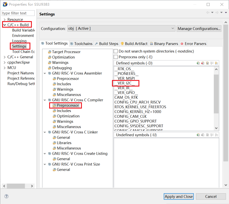
Figure 5-1: RISCV-2
2) Test demo path
sc/driver/sysdriver/i2c/drv/pub/drv_iic.h

sc/driver/sysdriver/i2c/drv/src/drv_iic_test.c
3) Test command
Compile and burn the riscv firmware according to the above configuration. Connect the riscv serial port and use the following command line for testing:
i2c [r/w] [port] [slave] [format] <data...> <speed> //i2c read and write
[r/w]: read or write
[port]: i2c channel
[slave]: slave address
[format]: i2c data format
<data...>: i2c data
<speed>: i2c read and write speed
5.3. I2C Development
Refer to RISCV_I2C USER GUIDE.
6. IR USAGE
6.1. Sysdecs Configuration
To use ir, you need to open the corresponding irX node through sysdecs configuration and configure padmux. Take ir0 as an example:
sc\driver\sysdriver\sysdesc\hal\pcupid\pub\pcupid-default.sys:
<ir0>
    [reg_u32_u16] 0x22CE200 0x200;
    [interrupts_u32_u32] INT_FIQ_IR_1 0xFFFF;
    [camclk_u32] CAMCLK_ir_nonpm0;
    [status_u8] 1;

<padmux>
    [schematic_u32_u32_u32]
        PAD_GPIOC_00 PINMUX_FOR_IR0_IN_MODE_1 MDRV_PUSE_IR,
        PAD_GPIOC_01 PINMUX_FOR_IR1_IN_MODE_1 MDRV_PUSE_IR1,
        PAD_GPIOC_02 PINMUX_FOR_IR2_IN_MODE_1 MDRV_PUSE_IR2,
        PAD_GPIOC_03 PINMUX_FOR_IR3_IN_MODE_1 MDRV_PUSE_IR3,
        PAD_PM_GPIO2 PINMUX_FOR_PM_IR_IN_MODE_1 MDRV_PUSE_IR4;
    [status_u8] 1;
6.2. Test Demo Usage
1) Open the ir test demo macro definition __VER_IR__
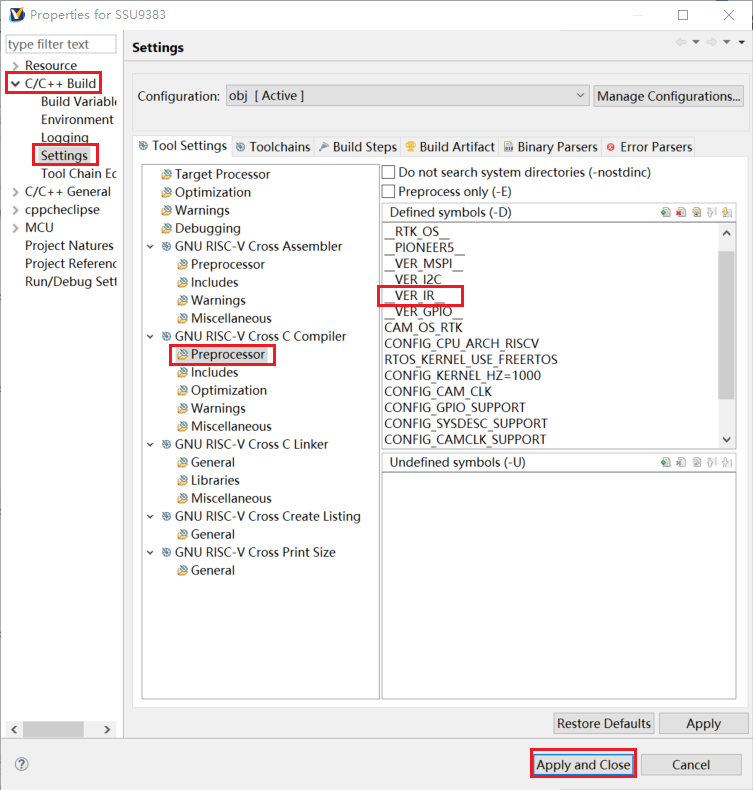
Figure 6-1: RISCV-3
2) Test demo path
sc/driver/sysdriver/ir/drv/pub/drv_ir.h

sc/driver/sysdriver/ir/drv/src/drv_ir_test.c
3) Test command
Compile and burn the riscv firmware according to the above configuration. Connect the riscv serial port and use the following command line for testing:
ir [group] [decode_mode] [customer code(16bit)] //Enable IR to receive signals and decode
[group]: Specify the group, optional 0~4
[decode_mode]: Decoding mode, 1: full, 2: raw, 3: rc5
[customer code(16bit)]: Custom 16bits decoding
6.3. IR Development
Refer to RISCV_IR USER GUIDE.
7. MSPI USAGE
7.1. Configuration
Sysdecs configuration:
To use mspi, you need to open the mspiX node through sysdecs configuration and configure padmux. Take mspi0 mode1 as an example:
sc\driver\sysdriver\sysdesc\hal\pcupid\pub\pcupid-default.sys:
<mspi0>
    [reg_u32_u16] 0x2222000 0x200;
    [interrupts_u8] INT_IRQ_MSPI_1;
    [camclk_u16] CAMCLK_mspi1;
    [dma_u8] 0;
    [cs_num_u8] 2;
    [cs_ext_u32] PAD_UNKNOWN;
    [pad_mux_u16] 0;
    [4to3_mode_u8] 0;
    [clk_out_mode_u32] 0;
    [status_u8] 1;

<padmux>
    [schematic_u32_u32_u32]
        PAD_GPIOE_14   PINMUX_FOR_MSPI0_MODE_1    MDRV_PUSE_SPI0_CK,
        PAD_GPIOE_15   PINMUX_FOR_MSPI0_MODE_1    MDRV_PUSE_SPI0_CZ,
        PAD_GPIOE_16   PINMUX_FOR_MSPI0_MODE_1    MDRV_PUSE_SPI0_DI,
        PAD_GPIOE_17   PINMUX_FOR_MSPI0_MODE_1    MDRV_PUSE_SPI0_DO,
    [status_u8] 1;
7.2. Test Demo Usage
1) Open the mspi test demo macro definition __VER_MSPI__
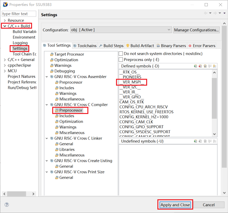
Figure 7-1: RISCV-4
2) Test demo path
sc/driver/sysdriver/mspi/drv/pub/drv_mspi.h

sc/driver/sysdriver/mspi/drv/src/drv_mspi_test.c
3) Test command
Compile and burn the riscv firmware according to the above configuration. Connect the riscv serial port and use the following command line for testing:
spi [r/e/w] [port] [cs] [speed] //spi read/write/erase
[r/e/w]: read/write/erase
[port]: mspi channel
[cs]: chip select
[speed]: communication speed
7.3. SPI Development
Refer to RISCV_SPI USER GUIDE.
8. UART USAGE
8.1. Configuration
Sysdecs configuration:
To use uart, you need to open the uartX node through sysdecs configuration and configure padmux. Take fuart mode2 as an example:
sc\driver\sysdriver\sysdesc\hal\pcupid\pub\pcupid-default.sys:
<fuart>
    [reg_u32] 0x2220400, 0x2220600;
    [interrupts_u32] INT_IRQ_FUART,
                    INT_IRQ_UART_MERGE,
                    INT_IRQ_UART_MERGE;
    [camclk_u16] CAMCLK_fuart;
    [pad_u16] 2;
    [sctpen_u8] 0;
    [dma_u8] 0;
    [digmux_u8] 1;
    [status_u8] 1;

<padmux>
    [schematic_u32_u32_u32]
        PAD_GPIOC_02    PINMUX_FOR_FUART_MODE_2    MDRV_PUSE_FUART_RX,
        PAD_GPIOC_03    PINMUX_FOR_FUART_MODE_2    MDRV_PUSE_FUART_TX,
        PAD_GPIOC_04    PINMUX_FOR_FUART_MODE_2    MDRV_PUSE_FUART_CTS,
        PAD_GPIOC_05    PINMUX_FOR_FUART_MODE_2    MDRV_PUSE_FUART_RTS;
    [status_u8] 1;
8.2. Test Demo Usage
1) The uart test demo is enabled by default, no macro configuration is required.
2) Test demo path
sc/driver/sysdriver/uart/drv/pub/drv_uart.h

sc/driver/sysdriver/uart/drv/src/drv_uart_test.c
3) Test command
Compile and burn the riscv firmware according to the above configuration. Connect the riscv serial port and use the following command line for testing:
uart [uartID] //uart read and write
[uartID]: uart channel, uart0~uart8 plus fuart and pm_uart
8.3. UART Development
Refer to RISCV_UART USER GUIDE.
9. Capture USAGE
9.1. Sysdecs Configuration
To use the capture function, you need to open the corresponding captureX node through sysdecs configuration and configure the capture-related padmux. Take capture0 as an example.
sc\driver\sysdriver\sysdesc\hal\pcupid\pub\pcupid-default.sys:
<capture0>
    [reg_u32] 0x22CE000;
    [interrupts_u32] INT_IRQ_CAPTURE;
    [camclk_u16] CAMCLK_pwm_capture;
    [channel_u8] 0, 1;
    [pulse_cal_mode_u8] 0;
    [pulse_cal_chan_u8] 0;
    [deglitch_u32] 0;
    [status_u8] 1;

<padmux>
    [schematic_u32_u32_u32]
        PAD_OUTP_CH0   PINMUX_FOR_PWMIN0_MODE_1 MDRV_PUSE_PWMIN0,
        PAD_OUTN_CH0   PINMUX_FOR_PWMIN1_MODE_1 MDRV_PUSE_PWMIN1,
        PAD_OUTP_CH1   PINMUX_FOR_PWMIN2_MODE_1 MDRV_PUSE_PWMIN2,
        PAD_OUTN_CH1   PINMUX_FOR_PWMIN3_MODE_1 MDRV_PUSE_PWMIN3,
        PAD_OUTP_CH2   PINMUX_FOR_PWMIN4_MODE_1 MDRV_PUSE_PWMIN4,
        PAD_OUTN_CH2   PINMUX_FOR_PWMIN5_MODE_1 MDRV_PUSE_PWMIN5,
        PAD_OUTP_CH3   PINMUX_FOR_PWMIN6_MODE_1 MDRV_PUSE_PWMIN6,
        PAD_OUTN_CH3   PINMUX_FOR_PWMIN7_MODE_1 MDRV_PUSE_PWMIN7,
        PAD_GPIOE_10   PINMUX_FOR_PWMIN8_MODE_3 MDRV_PUSE_PWMIN8,
        PAD_GPIOD_00   PINMUX_FOR_PWMIN9_MODE_2 MDRV_PUSE_PWMIN9,
        PAD_GPIOE_14   PINMUX_FOR_PWMIN10_MODE_3 MDRV_PUSE_PWMIN10,
        PAD_GPIOE_16   PINMUX_FOR_PWMIN11_MODE_3 MDRV_PUSE_PWMIN11;
    [status_u8] 1;
9.2. Test Demo Usage
1) Open the pwm test demo macro definition: __VER_CAPTURE__
2) Test demo path
sc/driver/sysdriver/capture/drv/pub/drv_capture.h

sc/driver/sysdriver/capture/drv/src/drv_capture_test.c
3) Test command
Compile and burn the riscv firmware according to the above configuration. Connect the riscv serial port and use the following command line for testing:
capture <config> [group] [channel] [edge] [enable] //Set the edge capture mode of the group and channel specified by capture, and enable it
[group] Specify the capture group, optional 0~7
[channel]: Specify the capture channel, group0 can be 0~1, group1 can be 2~3, group2 can be 4~5, group3 can be 6~7, group4 can be 8, group5 can be 9, group6 can be 10, group7 can be 11

capture <period> [group] [channel] //Capture the frequency and duty cycle of the pwm period
[group] Specify the capture group, optional 0~7
[channel]: Specify the capture channel, group0 can be 0~1, group1 can be 2~3, group2 can be 4~5, group3 can be 6~7, group4 can be 8, group5 can be 9, group6 can be 10, group7 can be 11

capture <pulse> [group] [channel] //Capture the number of pulses
[group] Specify the capture group, optional 0~7
[channel]: Specify the capture channel, group0 can be 0~1, group1 can be 2~3, group2 can be 4~5, group3 can be 6~7, group4 can be 8, group5 can be 9, group6 can be 10, group7 can be 11
9.3. Capture Development
Refer to RISCV_Capture USER GUIDE.