CAPTURE USER GUIDE
REVISION HISTORY
| Revision No. | Description |
Date |
|---|---|---|
| 1.0 | 04/09/2025 |
1. OVERVIEW
1.1. Capture
Capture can capture PWM waveform information, including period, duty cycle and number of pulses. The principle of Capture is to obtain the PWM waveform information by capturing the rising and falling edges of the PWM waveform and their time intervals. It should be noted that the captured waveform duty cycle range should be 0% < duty < 100%, because when the duty cycle is 0% or 100%, there is no rising and falling edge, and the jump cannot be captured to obtain the input PWM waveform information.
The clock frequency of Capture is 24Mhz, and switching is not supported.
1.2. channel
Capture has 8 groups, of which the first 4 groups have 2 channels each, and the last 4 groups have 1 channel each, there are 12 channels to support capture in total.
Capture supports up to 12 channels to capture PWM period and duty cycle at the same time, but each group has only 1 channel to capture the number of pulses, so it supports up to 8 channels to capture the number of pulses at the same time.
2. Key Words
dts/dtsi:
Linux Device Tree File, commonly used to describe the peripherals supported by the CPU. The attribute values contained in the peripheral nodes can be used for the configuration of the peripherals.
padmux:
Pin Multiplexing, used to connect the functional pins of a module to specific external pins, thereby establishing signal connections.
deglitch:
Glitch filtering: waveforms shorter than the deglitch value (in ns) will be ignored. The setting of deglitch affects the upper limit of the captured PWM frequency
3. Function Description
Support three modes of pulse number capture: normal mode, direction mode, quad mode.the captured frequency range is 1Hz ~ 6MHz.
3.1. Pulse Counting Mode--Normal Mode
All 8 capture groups support normal mode. After capturing two rising edges, the count increases by 1. The maximum value is 0xFFFF, and overflow is cleared to 0.
3.2. Pulse Counting Mode--Direction Mode
Only the first 4 groups Capture0-Capture3 support direction mode. Each group has two channels, one for pulse counting and the other for direction judgment.
When the channel as the direction captures a high level, the pulse count starts to increase, the maximum value is 0xFFFF, and overflow is cleared to 0.
When the channel as the direction captures a low level, the pulse count starts to decrease, the maximum value is 0xFFFF, gradually decreases to 0 and then jumps to 0xFFFF, repeating the cycle.
3.3. Pulse Counting Mode--Quad Mode
The quad mode is also called orthogonal encoding counting mode. It is only supported by the first 4 groups Capture0-Capture3, with two channels in each group.
By capturing PWM signals with the same signal and a phase difference of 90 degrees (i.e. orthogonal signals), the number and direction of pulses are calculated.
As shown in the figure, quad mode means 4 times counting. The number of pulses will be increased by 1 only when the counting at the 4 moments in the figure is met, so it has a higher counting accuracy.
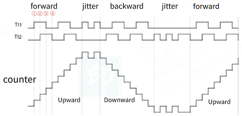
As shown in the figure, pulses count on both edges of TI1 and TI2, among which,
Moment 1: TI2 is at a low level, TI1 has an upward edge transition, the counter counts up
Moment 2: TI1 is at a high level, TI2 has an upward edge transition, the counter continues to count up
Moment 3: TI2 is at a high level, TI1 has a downward edge transition, the counter continues to count up
Moment 4: TI1 is at a low level, TI2 has a downward edge transition, the counter continues to count up
4. KERNEL USAGE INTRODUCTION
Driver Path: kernel/drivers/sstar/capture
4.1. Kernel Config Configuration
The configurations you need to select when compiling the kernel are as follows:
Device Drivers-->
    [*] SStar SoC platform drivers-->
        [*] Sigmastar Capture driver
4.2. Configure DTS
The DTS configuration of Capture only needs to configure the following information in the corresponding chipname.dtsi:
capture0: capture@1f2ce000 {
    compatible = "sstar,capture";
    reg = <0x0 0x1F2CE000 0x0 0x80>;
    interrupts=<GIC_SPI INT_IRQ_CAPTURE IRQ_TYPE_LEVEL_HIGH>;
    group = <0>;
    channel = <0 1>;
    //0: normal mode,  1: quad mode, 2: dir mode
    pulse-cal-mode = <0>;
    pulse-cal-chan = <0>;
    deglitch = <0>;
    clocks = <&CLK_pwm_capture>;
    status = "ok";
};

.......

capture4: capture@1f2cf800 {
    compatible = "sstar,capture";
    reg = <0x0 0x1F2CF800 0x0 0x80>;
    interrupts=<GIC_SPI INT_IRQ_CAPTURE IRQ_TYPE_LEVEL_HIGH>;
    group = <4>;
    channel = <8>;
    //only support 0: normal mode
    pulse-cal-mode = <0>;
    pulse-cal-chan = <8>;
    deglitch = <0>;
    clocks = <&CLK_pwm_capture>;
    status = "ok";
};
Capture DTS configuration description:
| Attribute | Description | Setting Value | Remark |
|---|---|---|---|
| compatible | Match the driver for registration, which must be consistent with the code | "sstar,capture" | Modification prohibited |
| reg | Set the address of the register bank | / | Modification prohibited |
| interrupts | Specify the hardware interrupt number and attributes to be used | INT_IRQ_CAPTURE | Modification prohibited |
| group | The group ID to which each channel belongs | / | Modification prohibited |
| channel | The channel ID under each group | / | Modification prohibited |
| pulse-cal-mode | Select different pulse counting modes, please refer to Pulse Counting Mode Description | Capture0~3 supports 0~2, Capture4~7 only supports 0 | Can be modified as needed |
| pulse-cal-chan | Select the channel for capturing the number of pulses | Capture0~3 supports 2-choose-1, Capture4~7 only supports 1 channel | Can be modified as needed |
| deglitch | Set the pulse to be filtered | In ns, for example, if the setting value is 7, then pulses with a high level duration shorter than 24M * 7 = 291.67ns cannot be captured | Can be modified as needed |
| clocks | Specify the clock source to be used | CLK_pwm_capture | Modification prohibited |
| status | Select whether to enable the Capture driver | "ok" or "disable" | Can be modified as needed |
4.3. PADMUX CONFIGURATION
The padmux configuration of Capture needs to add the following code to the corresponding arch/arm64/boot/dts/sstar/chipname-xxx-padmux.dtsi according to the selected pin:
<PAD_OUTP_CH0   PINMUX_FOR_PWMIN0_MODE_1 MDRV_PUSE_PWMIN0>,
<PAD_OUTN_CH0   PINMUX_FOR_PWMIN1_MODE_1 MDRV_PUSE_PWMIN1>,
<PAD_OUTP_CH1   PINMUX_FOR_PWMIN2_MODE_1 MDRV_PUSE_PWMIN2>,
<PAD_OUTN_CH1   PINMUX_FOR_PWMIN3_MODE_1 MDRV_PUSE_PWMIN3>,
<PAD_OUTP_CH2   PINMUX_FOR_PWMIN4_MODE_1 MDRV_PUSE_PWMIN4>,
<PAD_OUTN_CH2   PINMUX_FOR_PWMIN5_MODE_1 MDRV_PUSE_PWMIN5>,
<PAD_OUTP_CH3   PINMUX_FOR_PWMIN6_MODE_1 MDRV_PUSE_PWMIN6>,
<PAD_OUTN_CH3   PINMUX_FOR_PWMIN7_MODE_1 MDRV_PUSE_PWMIN7>,
<PAD_GPIOE_10   PINMUX_FOR_PWMIN8_MODE_3 MDRV_PUSE_PWMIN8>,
<PAD_GPIOD_00   PINMUX_FOR_PWMIN9_MODE_2 MDRV_PUSE_PWMIN9>,
<PAD_GPIOE_14   PINMUX_FOR_PWMIN10_MODE_3 MDRV_PUSE_PWMIN10>,
<PAD_GPIOE_16   PINMUX_FOR_PWMIN11_MODE_3 MDRV_PUSE_PWMIN11>,
The first column is the pin index number, which can be found in /drivers/sstar/inlcude/{chipname}/gpio.h;
The second column is the mode definition. The hal_gpio_st_padmux_info array in /drivers/sstar/gpio/{chipname}/hal_pinmux.c lists the multiplexing relationship of all pins, which can be used to query which multiplexing functions the pin supports;
The third column is the index name of the pin and the matching mode, which can be found in /drivers/sstar/include/drv_puse.h.
4.4. Module Usage Introduction
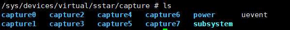
4.4.1 sys/class/sstar/capture
The directory structure of sys/class/sstar/capture is as follows:
-
First-level directory
Create different groups according to the status of DTS Capture.
-
Second-level directory
Each group of Capture attribute settings.

Each File Interface Usage Introduction:
| Name | Description | Parameter | Remark |
|---|---|---|---|
| capture | Get the captured frequency and duty cycle | echo [channel id] > capture;cat capture | |
| cap_edge | Set the edge sampling mode when capturing period and duty cycle | echo [channel id] [edge mode] > cap_edge | edge mode: 0 -> rising edge, 1 -> falling edge, 2 -> dual edges |
| cap_enable | Enable capture | echo [enable] > cap_enable | 0->disable 1->enable |
| pulse | Get the number of captured pulses | cat pulse | The channel to be captured is determined by DTS |
| pulse_edge | Set the edge sampling mode when capturing the number of pulses | echo [edge mode] > pulse_edge | edge mode: 0 -> rising edge, 1 -> falling edge, 2 -> dual edges, note that the number of pulses captured by a single edge is a multiple of that by a double edge. |
| pulse_enable | Enable capture | echo [enable] > pulse_enable | 0->disable 1->enable |
| pulse_bound | Set the upper and lower limits of capture in quad mode | echo [max] [min]> pulse_bound | Only supports quad mode. When the direction is positive, reaching max will trigger an interrupt and clear the captured pulse value to 0. When the direction is negative, reaching min will trigger an interrupt and clear the captured pulse value to 0. |
| direction | Get the direction of the captured pulse | cat direction | 0->negative 1->positive |
| timeout | Set the capture timeout | echo [channel id] [time ns] > time_out | If the capture result does not change within the specified time, the software determines that the input source has been disconnected and the capture fails. It can be used for capturing at a lower frequency. |
For example: Use channel0 of Capture0 to capture frequency, duty cycle and number of pulses.
1.    #Jump to Capture0 path
2.    cd sys/class/sstar/capture0/
3.
4.     #Set Capture related attributes
5.     echo 0 2 > cap_edge
6.     echo 1   > cap_enable
7.     echo 1   > pulse_edge
8.     echo 1   > pulse_enable
9.
10.    #Get capture results
11.    echo 0 > capture;
12.    cat capture;
13.    cat pulse;
14.    cat direction;
4.5 Demo code
Besides sysfs, capture also provides an ioctl interface
#include <stdio.h>
#include <errno.h>
#include <fcntl.h>
#include <stdlib.h>
#include <unistd.h>
#include <signal.h>
#include <string.h>
#include <sys/stat.h>
#include <sys/types.h>
#include <sys/ioctl.h>
#include <drv_capture.h>

void capture_warn(int num)
{
    printf("capture pulse exceeding the threshold\n");
}

int main(int argc, char **argv)
{
    u8                    id;
    char                  cmd;
    int                   flags;
    int                   fd = -1;
    char                  path_name[24];
    struct capture_info   info;
    struct capture_config cap_cfg;

    if (argc != 5)
    {
        printf("format: ut_capture [channel] [cap_edge] [pul_edge] [enable]\n");
        return -1;
    }

    info.channel        = atoi(argv[1]);
    cap_cfg.channel     = atoi(argv[1]);
    cap_cfg.cap_edge    = atoi(argv[2]);
    cap_cfg.pul_edge    = atoi(argv[3]);
    cap_cfg.cap_enable  = atoi(argv[4]);
    cap_cfg.pul_enable  = atoi(argv[4]);
    cap_cfg.quad_pul_up = 20000;
    cap_cfg.quad_pul_dn = 20000;
    cap_cfg.timeout     = 10000000000;

    if (cap_cfg.channel >= 0 && cap_cfg.channel <= 1)
    {
        id = 0;
    }
    else if (cap_cfg.channel >= 2 && cap_cfg.channel <= 3)
    {
        id = 1;
    }
    else if (cap_cfg.channel >= 4 && cap_cfg.channel <= 5)
    {
        id = 2;
    }
    else if (cap_cfg.channel >= 6 && cap_cfg.channel <= 7)
    {
        id = 3;
    }
    else if (cap_cfg.channel == 8)
    {
        id = 4;
    }
    else if (cap_cfg.channel == 9)
    {
        id = 5;
    }
    else if (cap_cfg.channel == 10)
    {
        id = 6;
    }
    else if (cap_cfg.channel == 11)
    {
        id = 7;
    }
    else
    {
        printf("unsupport channel\n");
        return -1;
    }

    snprintf(path_name, sizeof(path_name), "/dev/capture%hhu", id);
    fd = open((const char *)(char *)path_name, O_RDWR);
    if (fd < 0)
    {
        printf("open /dev/capture%hhu fail errno:[%d]\n", id, fd);
        return -1;
    }

    if (ioctl(fd, IOCTL_CAPTURE_SET_CONFIG, &cap_cfg))
    {
        printf("capture[%hhu] config fail\n", cap_cfg.channel);
        close(fd);
        return -1;
    }

    signal(SIGIO, capture_warn); //Trigger when quad mode reaches the upper and lower limits

    fcntl(fd, F_SETOWN, getpid());
    flags = fcntl(fd, F_GETFL);
    fcntl(fd, F_SETFL, flags | FASYNC);

    while (1)
    {
        cmd = getchar();
        if (cmd == 'q' || cmd == 'Q')
        {
            break;
        }

        if (ioctl(fd, IOCTL_CAPTURE_RD_PERIOD, &info))
        {
            printf("capture[%hhu] read period fail\n", info.channel);
            close(fd);
            return -1;
        }
        printf("capture period [%llu]ns , duty [%llu.%02llu]%% \n", info.period, info.duty_i, info.duty_d);

        if (ioctl(fd, IOCTL_CAPTURE_RD_PULSE, &info))
        {
            printf("capture[%hhu] read pulse fail\n", info.channel);
        }
        else
        {
            printf("capture pulse [%u] dir[%hhu]\n", info.pulse, info.dir);
        }
    }

    close(fd);

    return 0;
}
5. API Reference
| Cmd | Function |
|---|---|
| IOCTL_CAPTURE_SET_CONFIG | Set the capture attributes for the specified channel |
| IOCTL_CAPTURE_GET_CONFIG | Get the current capture attributes for the channel |
| IOCTL_CAPTURE_RD_PERIOD | Get the current period |
| IOCTL_CAPTURE_RD_PULSE | Get the current pulse count |
Before using, include the header file /driver/sstar/capture/drv_capture.h, where the data structures are defined as follows:
struct capture_config
{
    u8  channel;     // Specify the capture channel
    u64 timeout;     // Set the timeout period in nanoseconds (ns)
    u8  cap_edge;    // Set the edge mode for capturing period and duty cycle
    u8  pul_edge;    // Set the edge mode for capturing pulse count
    u8  cap_enable;
    u8  pul_enable;
    u16 quad_pul_up;     // Set the upper limit for pulse capture in quad mode
    u16 quad_pul_dn;     // Set the lower limit for pulse capture in quad mode
};

struct capture_info
{
    u8  dir;      // Direction during pulse capture
    u32 pulse;    // Number of captured pulses
    u64 period;   // Captured period
    u64 duty_i;   // Integer part of the captured duty cycle
    u64 duty_d;   // Decimal part of the captured duty cycle
    u8  channel;
};
5.1. IOCTL_CAPTURE_SET_CONFIG
-
Function
Set the capture attributes for the corresponding device from the cfg file。
-
Declaration
ioctl(struct file *file, IOCTL_CAPTURE_SET_CONFIG,struct capture_config *cfg);
-
Parameters
Parameter Name Description file Device node IOCTL_CAPTURE_SET_CONFIG Command cfg Structure for storing configurations -
Return Value
Return Value Description 0 Success other Failure
5.2. IOCTL_CAPTURE_GET_CONFIG
-
Function
Get the capture attributes for the device corresponding to the file and return them to cfg.
-
Declaration
ioctl(struct file *file, IOCTL_CAPTURE_GET_CONFIG,struct capture_config *cfg);
-
Parameters
Parameter Name Description file Device node IOCTL_CAPTURE_GET_CONFIG Command cfg Structure for storing configurations -
Return Value
Return Value Description 0 Success other Failure
5.3. IOCTL_CAPTURE_RD_PERIOD
-
Function
Get the current period for the device corresponding to the file and return it to info.
-
Declaration
ioctl(struct file *file, IOCTL_CAPTURE_RD_PERIOD,struct capture_info *info);
-
Parameters
Parameter Name Description file Device node IOCTL_CAPTURE_RD_PERIOD Command info Structure for storing capture information -
Return Value
Return Value Description 0 Success other Failure
5.4. IOCTL_CAPTURE_RD_PULSE
-
Function
Get the current pulse count for the device corresponding to the file and return it to info.
-
Declaration
ioctl(struct file *file, IOCTL_CAPTURE_RD_PULSE, struct capture_info *info);
-
Parameters
Parameter Name Description file Device node IOCTL_CAPTURE_RD_PULSE Command info Structure for storing capture information -
Return Value
Return Value Description 0 Success other Failure
6. FAQ
6.1. Each Capture Interface Does Not Exist
-
Check whether the
statusof the DTS Capture node isok. -
Check whether the kernel config is configured, see Kernel Config Configuration.
6.2. Capture Results Are Abnormal or Timed out After Configuration
Step 1: First confirm whether the measured pin is correct: open the corresponding schematic to confirm, if there is no error, proceed to the next step.
Step 2: Confirm whether the corresponding Capture pad mode is effective. There are two main reasons for pin multiplexing failure:
Reason 1: The pin is not set to Capture mode. For details on the setting method, see PADMUX Configuration.
Reason 2: A padmux mode with a higher priority than Capture mode is enabled. You can turn on the padmux readback mechanism CONFIG: CONFIG_MSYS_PADMUX during compilation. Its function is to confirm whether the padmux used has been successfully set. After turning it on, enter the following command in user space to check:
echo [pad index] [pinmux index] > /sys/class/sstar/msys/mux_verify

cat /sys/class/sstar/msys/mux_verify
Step 3: Check whether the relevant parameters are set successfully.
Please refer to Sysfs Interface Usage Instructions for standard usage.