MI PSPI API
REVISION HISTORY
| Revision No. | Description |
Date |
|---|---|---|
| 1.00 | 25/09/2020 | |
| 2.00 | 18/04/2025 |
1. Overview
1.1. Module Description
PSPI is based on the SPI communication protocol and is designed to achieve communication between Sensor and Panel.
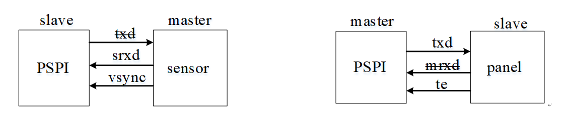
When PSPI is used as a Slave, it can communicate with the Sensor. Vsync is the indication signal from the Sensor to PSPI, indicating that the Sensor is ready to send a frame of image, and its valid signal is high level.
When PSPI is used as a Master, it can communicate with the Panel. Te is the indication signal from the Panel to PSPI, indicating that the Panel has started to refresh all internal buffers to the display, and its valid signal is high level.
1.2. Basic structure
PSPI is not currently connected to other MI modules, and its functions are mainly implemented through the development of the application layer.
When the hardware is connected to the Pannel, the initialization of the Pannel is implemented by the application layer calling the function MI_PSPI_Transfer() to pass in the screen parameters, and then the application layer continuously passes the image data to the PSPI Master;
When the hardware is connected to the Sensor, the initialization of the Sensor is implemented by the application layer calling the function MI_PSPI_Enable(), which will trigger the init flow that has been set for the sensor, and then obtain the sensor data through the PSPI Slave.

1.3. Functional introduction
-
Support polarity and phase configuration of SPI clock (SCLK)
-
Support polarity switching of chip select (SS) signal
-
Single transmission word length can be selected from 3 to 32 bits
-
Allow chip select (SS) signal to remain valid between word transmissions
-
Support FIFO mode and DMA mode
-
Support dual-channel/quad-channel mode reading and writing in DMA mode through BDMA
-
Support single-channel/dual-channel writing of RGB565 and BRG565 in DMA mode
-
Support reception of TE signal and VSYNC signal
-
Support skipping TE signal times, the times can be selected from 0 to 15
-
Support polarity switching of TE signal
1.4. Application scenarios
PSPI can be applied to the following scenarios:
- Pure Linux scenario
Develop based on the API interface provided by PSPI in the Linux environment
1.5. Chip differences
The differences between PSPI on different chips are mainly reflected in the different PAD MODE settings affecting different communication functions. In the following list, 1 indicates support, and 0 indicates unsupport.
The chip described in this document is pcupid.
1.5.1. Ikayaki
| CHIP | PAD MODE | MODE INDEX | 3wire mode | 4wire mode | dual mod | equal mod | master tx | master rx | slave tx | slave rx |
|---|---|---|---|---|---|---|---|---|---|---|
| Ikayaki | reg_pspi0_g_mode | mode 1 | 1 | 0 | 0 | 0 | 1 | 1 | 1 | 1 |
| mode 2 | 1 | 0 | 1 | 1 | 1 | 1 | 1 | 1 | ||
| reg_pspi0_sr_mode | mode 1 | 1 | 0 | 1 | 1 | 1 | 0 | 0 | 1 | |
| mode 2 | 1 | 0 | 1 | 1 | 1 | 0 | 0 | 1 | ||
| mode 3 | 1 | 0 | 1 | 0 | 1 | 0 | 0 | 1 | ||
| mode 4 | 1 | 0 | 1 | 0 | 1 | 0 | 0 | 1 | ||
| mode 5 | 1 | 0 | 0 | 0 | 1 | 0 | 0 | 1 | ||
| mode 6 | 1 | 0 | 0 | 0 | 1 | 0 | 0 | 1 | ||
| reg_pspi1_g_mode | mode 1 | 1 | 0 | 0 | 0 | 1 | 1 | 1 | 1 | |
| mode 2 | 1 | 0 | 1 | 1 | 1 | 1 | 1 | 1 | ||
| reg_pspi1_pl_mode | mode 1 | 1 | 0 | 1 | 0 | 1 | 0 | 0 | 1 | |
| mode 2 | 1 | 0 | 1 | 0 | 1 | 0 | 0 | 1 | ||
| mode 3 | 1 | 0 | 1 | 0 | 1 | 0 | 0 | 1 | ||
| mode 4 | 1 | 0 | 1 | 0 | 1 | 0 | 0 | 1 | ||
| mode 5 | 1 | 0 | 1 | 0 | 1 | 0 | 0 | 1 | ||
| mode 6 | 1 | 0 | 0 | 0 | 1 | 0 | 0 | 1 |
1.5.2. Opera
| CHIP | PAD MODE | MODE INDEX | 3wire mode | 4wire mode | dual mod | equal mod | master tx | master rx | slave tx | slave rx |
|---|---|---|---|---|---|---|---|---|---|---|
| Opera | reg_pspi0_g_mode | mode 1 | 1 | 0 | 1 | 1 | 1 | 1 | 1 | 1 |
| reg_pspi0_sensor_mode | mode 1 | 1 | 0 | 1 | 0 | 1 | 0 | 0 | 1 | |
| mode 2 | 1 | 0 | 1 | 1 | 1 | 0 | 0 | 1 | ||
| mode 3 | 1 | 0 | 0 | 0 | 1 | 0 | 0 | 1 | ||
| reg_pspi1_g_mode | mode 1 | 1 | 0 | 1 | 1 | 1 | 1 | 1 | 1 | |
| reg_pspi0_pannel_mode | mode 1 | 1 | 0 | 1 | 0 | 1 | 0 | 0 | 1 | |
| mode 2 | 1 | 0 | 1 | 0 | 1 | 0 | 0 | 1 |
1.5.3. Pcupid
| CHIP | PAD MODE | MODE INDEX | 3wire mode | 4wire mode | dual mod | equal mod | master tx | master rx | slave tx | slave rx |
|---|---|---|---|---|---|---|---|---|---|---|
| Pcupid | reg_pspi0_g_mode | mode 1 | 1 | 1 | 1 | 1 | 1 | 1 | 1 | 1 |
| reg_pspi0_mode | mode 1 | 1 | 0 | 1 | 1 | 1 | 0 | 1 | 1 | |
| mode 2 | 1 | 0 | 1 | 1 | 1 | 0 | 1 | 1 | ||
| mode 3 | 1 | 0 | 1 | 0 | 1 | 0 | 1 | 1 | ||
| mode 4 | 1 | 0 | 1 | 0 | 1 | 0 | 1 | 1 | ||
| mode 5 | 1 | 0 | 0 | 0 | 1 | 0 | 1 | 1 | ||
| reg_pspi1_g_mode | mode 1 | 1 | 1 | 1 | 1 | 1 | 1 | 1 | 1 | |
| reg_pspi1_mode | mode 1 | 1 | 0 | 1 | 0 | 1 | 0 | 1 | 1 | |
| mode 2 | 1 | 0 | 1 | 0 | 1 | 0 | 1 | 1 | ||
| mode 3 | 1 | 1 | 0 | 0 | 1 | 1 | 1 | 1 | ||
| mode 4 | 1 | 0 | 1 | 1 | 1 | 0 | 1 | 1 | ||
| mode 5 | 1 | 0 | 1 | 1 | 1 | 1 | 1 | 0 |
1.6. Working Principle
PSPI is based on the SPI communication protocol, so it has all the SPI communication features. It is essentially data transmission and reception, so only the special communication mode of PSPI is described.
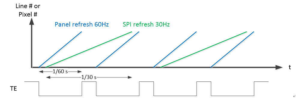
1.6.1. TE Mode
Generally, Pannel can dynamically start and stop the synchronization signal by operating the TE Line On/Off command. PSPI can receive TE signals for signal synchronization to prevent screen tearing.
In addition, PSPI supports skipping 0~15 TE signals so that PSPI can be delayed when the TE signal is triggered.
For example: if the number of skips is set to 2, each time PSPI receives a TE signal, the following two TE signals will be skipped.
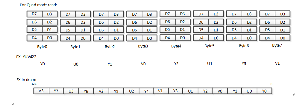
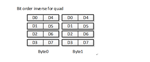
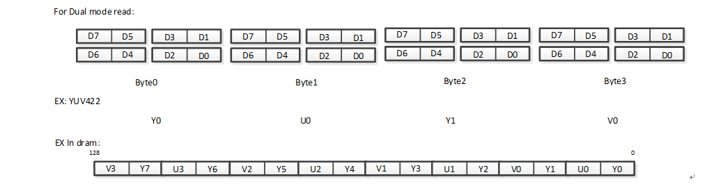
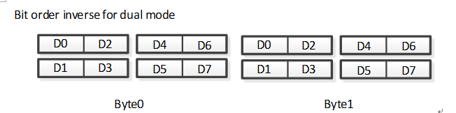
1.6.2. Quad/Dual Mode Read Data Format
PSPI supports bit order reversal in Quad Mode/Dual Mode
Quad Mode regular read is as follows:
Quad Mode bit order reversal read is as follows:
Dual Mode regular read is as follows:
Dual Mode bit order reversal read is as follows:
1.7. Development Process
1.7.1. Compile Configuration
Compile KO
Select defconfig, enter the project directory, make menuconfig and open MI_PSPI
Sdk Config-->
    [*] Interface Compile Config -->
        [*] pspi -->
            [*] nhal_pspi
            [*] mi_pspi
            (bf3901.ko gc032a.ko) PSPIDEV List
            (bf3901.ko) PSPIDEV0
            (pspi_id=1 pspi_slave=0x6e) PSPIDEV0 Opt
After compiling and successfully burning, the module mi_pspi.ko and pspi device will be automatically loaded at booting.
PSPIDEV List: Select pspi device, the source code is located in the sdk/driver/PspiDriver/drv directory, for example, the bf301 sensor. The source code is named drv_pspi_bf3901.c, after adding to the List, it will compile and generate bf3901.ko.
PSPIDEV0: Select the pspi device module that will be automatically insmoded after successful burning and startup. According to the above content, after startup, the program will first insmod mi_pspi.ko and then insmod drv_pspi_bf3901.ko.
PSPIDEV0 Opt: Select the input parameters when insmod device ko, pspi_id=1 means to bind bf3901 to pspi bus1, pspi_slave=0x6e means to fill in the slave address of this sensor = 0x6e.
Custom KO
Add files to the directory sdk/driver/PspiDriver/drv, and the naming method is fixed to drv_pspi_xxx.ko, where xxx is the device model. You can refer to drv_pspi_bf3901.c and complete the two parts of the structure information xxx_liner and PSPI_SENSOR_InitTable.
bf3901_linear describes pixel array and fps of sensor
static struct {
    struct _senout{
        s32 width, height, min_fps, max_fps;
    }senout;

    struct _senstr{
        const char* strResDesc;
    }senstr;

}bf3901_linear[] = {
    { {240, 320, 0, 30}, {"240x320@30fps"}},
};
PSPI_SENSOR_InitTable fills in the sensor initialization command in the format of registers and values. If a delay is required after setting a register, the value can be filled in as 0xffff
const static IIC_ARRAY_t PSPI_SENSOR_InitTable[] =
{
    {0x12, 0x80},
    {0x11, 0xb0},
    {0x1b, 0x80},
    {0x6b, 0x01},
    {0x12, 0x20},
    {0x3a, 0x00},
    ......
    {0x13, 0x05},
    {0x6a, 0x81},
    {0x23, 0x00},
    {0x01, 0x08},
    {0x02, 0x08},
};
1.7.2. PADMUX Configuration
Take PSPI0 connecting to Sensor as an example:
Enter directorykernel/driver/arch/arm64/boot/dts/sstar/chipname-xxx-padmux.dtsi,Configured PSPI0 as MODE1
<PAD_OUTP_RX0_CH0        PINMUX_FOR_PSPI0_MODE_1          MDRV_PUSE_PSPI1_CS>,
<PAD_OUTN_RX0_CH0        PINMUX_FOR_PSPI0_MODE_1          MDRV_PUSE_PSPI1_VSYNC>,
<PAD_OUTP_RX0_CH1        PINMUX_FOR_PSPI0_MODE_1          MDRV_PUSE_PSPI1_CLK>,
<PAD_OUTN_RX0_CH1        PINMUX_FOR_PSPI0_MODE_1          MDRV_PUSE_PSPI1_MISO0>,
<PAD_OUTP_RX0_CH2        PINMUX_FOR_PSPI0_MODE_1          MDRV_PUSE_PSPI1_MISO1>,
<PAD_OUTN_RX0_CH2        PINMUX_FOR_PSPI0_MODE_1          MDRV_PUSE_PSPI1_MISO2>,
<PAD_OUTP_RX0_CH3        PINMUX_FOR_PSPI0_MODE_1          MDRV_PUSE_PSPI1_MISO3>,
<PAD_GPIOB_02            PINMUX_FOR_SR00_MCLK_MODE_2      MDRV_PUSE_SR00_MCLK>,
Take PSPI1 connecting to Pannel as an example:
Enter directorykernel/driver/arch/arm64/boot/dts/sstar/chipname-xxx-padmux.dtsi,Configured PSPI1 as MODE1
<PAD_GPIOA_12                PINMUX_FOR_PSPI1_MODE_1      MDRV_PUSE_PSPI1_CS>,
<PAD_GPIOA_13                PINMUX_FOR_PSPI1_MODE_1      MDRV_PUSE_PSPI1_CLK>,
<PAD_GPIOA_14                PINMUX_FOR_PSPI1_MODE_1      MDRV_PUSE_PSPI1_MOSI0>,
<PAD_GPIOA_15                PINMUX_FOR_PSPI1_MODE_1      MDRV_PUSE_PSPI1_MOSI1>,
<PAD_GPIOA_16                PINMUX_FOR_PSPI1_TE_MODE_1   MDRV_PUSE_PSPI1_TE>,
1.7.3. Running Environment Description
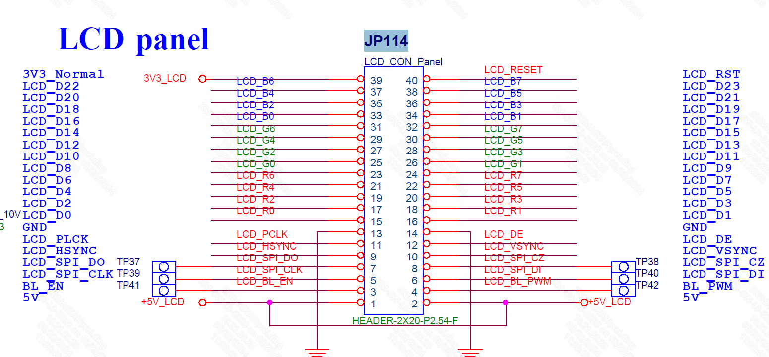
Hardware Connection Notes
The PIN pins of PSPI1 MODE1 are all concentrated in JP114. Please make sure the wiring is correct.
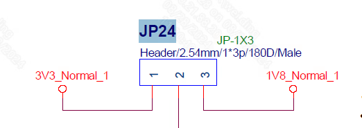
Switch JP24 to 3.3V
UT Program Running Instructions
Ensure that mi_pspi.ko file is loaded when the board starts, transplant the prog_pspi, reset.sh and dev0_sensor_datalane2_auto.json files to the board, and enter the command to run the UT program:
prog_pspi -i dev0_sensor_datalane2_auto.json -t 50000
-i specifies the json file; -t specifies the program running time in milliseconds
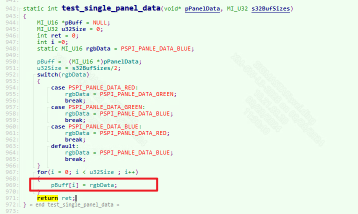
The image data passed into the panel uses red, green and blue by default. If you want to change it, you can modify it in sdk/verify/mi_demo/source/pspi/ut_pspi_main.c:
1.8. Example introduction
1.8.1. Sensor routine
int main(int argc, char *argv[])
{
    int fd = 0
    MI_PSPI_DEV   pspi_dev = 0;
    MI_PSPI_Param_t  pspi_para;
    MI_PSPI_OutputAttr_t stOutputAttr;
    MI_SYS_ChnPort_t stChnPort;
    MI_SYS_BufInfo_t stBufInfo;
    MI_SYS_BUF_HANDLE hSysBuf;
    memset(&stChnPort, 0x0, sizeof(MI_SYS_ChnPort_t));
    memset(&stBufInfo, 0x0, sizeof(MI_SYS_BufInfo_t));
    memset(&hSysBuf, 0x0, sizeof(MI_SYS_BUF_HANDLE));
    memset(&pspi_para, 0x0, sizeof(MI_PSPI_SpiParam_t));
    stChnPort.eModId    = E_MI_MODULE_ID_PSPI;
    stChnPort.u32DevId  = 0;
    stChnPort.u32ChnId  = 0;
    stChnPort.u32PortId = 0;
    stOutputAttr.u16Width   = 1920;
    stOutputAttr.u16Width   = 1080;
    stOutputAttr.ePixelFormat = E_MI_SYS_PIXEL_FRAME_YUV_SEMIPLANAR_420;
    pspi_para.u8BitsPerWord   = 8;
    pspi_para.u8DataLane      = DATA_DUAL;
    pspi_para.u16DelayCycle   = 0;
    pspi_para.u16WaitCycle    = 0;
    pspi_para.u8RgbSwap       = 0;
    pspi_para.u32MaxSpeedHz   = 1000000;
    pspi_para.u16PspiMode     = SPI_SLAVE;
    pspi_para.u8ChipSelect    = MI_PSPI_SELECT_0;
    pspi_para.ePspiType       =  E_MI_PSPI_TYPE_RX;
    pspi_para.eTriggerMode    = E_MI_PSPI_TRIGGER_MODE_AUTO;
    /***
    Send commands to sensor by IIC
    ***/
    MI_SYS_Init();
    MI_PSPI_CreateDevice(pspi_dev, &pspi_para);
    MI_PSPI_SetOutputAttr(&stOutputAttr);
    MI_PSPI_Enable(pspi_dev);
    MI_SYS_SetChnOutputPortDepth(&stChnPort,3,4);
GET_OUT_BUF:
    if (MI_SUCCESS != MI_SYS_ChnOutputPortGetBuf(&stChnPort, &stBufInfo, &hSysBuf))
    {
        goto GET_OUT_BUF;
    }
    fd = open(“picture”, O_RDWR|O_CREAT|O_TRUNC, 0777);
    write(fd, tBufInfo.stFrameData.pVirAddr[0], stBufInfo.stFrameData.u32BufSize));
    sync();
    close(fd);
PUT_OUT_BUF:
    if (MI_SUCCESS != MI_SYS_ChnOutputPortPutBuf(hSysBuf))
    {
        goto PUT_OUT_BUF;
    }
    MI_SYS_SetChnOutputPortDepth(&stChnPort,0,3);
    MI_PSPI_Disable(pspi_dev);
    MI_PSPI_DestroyDevice(pspi_dev);
    MI_SYS_Exit();
    Return 0;
}
1.8.2. Panel routine
int main(int argc, char *argv[])
{
    MI_S32 s32Ret = 0;
    MI_U16 * buff = NULL;
    MI_U32 size = 0;
    MI_PSPI_Msg_t  pspi_msg;
    MI_PSPI_Param_t  pspi_para;
    MI_PSPI_DEV   pspi_dev = 1;
    MI_SYS_ChnPort_t  stChnPort;
    MI_SYS_BUF_HANDLE  stHandle;
    MI_SYS_BufInfo_t   stBufInfo;s
    MI_SYS_BufConf_t  stBufConf;
    pspi_para.u8BitsPerWord    = 9;
    pspi_para.u8DataLane       = DATA_SINGLE;
    pspi_para.u16DelayCycle    = 2;
    pspi_para.u16WaitCycle     = 2;
    pspi_para.u8RgbSwap        = 0;
    pspi_para.u32MaxSpeedHz    = 1000000;
    pspi_para.u16PspiMode      = 0;
    pspi_para.u8ChipSelect     = MI_PSPI_SELECT_0;
    pspi_para.u8TeMode         = 0;
    MI_PSPI_CreateDevice(pspi_dev, &pspi_para);
    memset(&pspi_msg, 0 ,sizeof(MI_PSPI_Msg_t));
    pspi_msg.u8TxBitCount = 9;
    pspi_msg.u8RxBitCount = 8;
    pspi_msg.u8TxSize = 1;
    //0xDA
    pspi_msg.au16TxBuf[0] = 0xDA;
    MI_PSPI_Transfer(pspi_dev,  & pspi_msg);
    /****    Send commands to the panel   *****/
    memset(&stChnPort, 0, sizeof(MI_SYS_ChnPort_t));
    memset(&stBufConf, 0, sizeof(MI_SYS_BufConf_t));
    memset(&stBufInfo, 0, sizeof(MI_SYS_BufInfo_t));
    memset(&stHandle, 0, sizeof(MI_SYS_BUF_HANDLE));
    stChnPort.eModId = E_MI_MODULE_ID_PSPI;
    stChnPort.u32DevId = 1;
    stChnPort.u32ChnId = 0;
    stChnPort.u32PortId = 0;
    stBufConf.eBufType = E_MI_SYS_BUFDATA_FRAME;
    stBufConf.stFrameCfg.u16Height = 240;
    stBufConf.stFrameCfg.u16Width  = 320;
    stBufConf.stFrameCfg.eFrameScanMode = E_MI_SYS_FRAME_SCAN_MODE_PROGRESSIVE;
    stBufConf.stFrameCfg.eFormat    = E_MI_SYS_PIXEL_FRAME_RGB565;
    MI_PSPI_Enable(pspi_dev);
    while(1)
    {
        getBuff1:
        if (MI_SYS_ChnInputPortGetBuf(&stChnPort,&stBufConf,&stBufInfo,&stHandle,4000)!= MI_SUCCESS)
        {
            printf("get input port buf red failed\n");
            goto getBuff1;
        }
        else
        {
            printf("MI_SYS_ChnInputPortGetBuf success 1\n");
            buff =  (MI_U16 *)stBufInfo.stFrameData.pVirAddr[0];
            size = stBufInfo.stFrameData.u32BufSize/2;
            for(i = 0; i < size ; i++)
            {
                buff[i] = 0xf800;
            }
        putbuff1:
            if(MI_SYS_ChnInputPortPutBuf(stHandle, &stBufInfo, FALSE) != MI_SUCCESS)
            {
                printf("writter frame err 1\n");
                goto putbuff1;
            }
            else
                printf("written a frame red to screen success\n");
        }
    }
}
2. API Reference
2.1. API List
| API name | Features |
|---|---|
| MI_PSPI_CreateDevice | Create PSPI and configure PSPI properties |
| MI_PSPI_DestroyDevice | Destroy PSPI |
| MI_PSPI_Transfer | Send parameter information to PSPI, and configure the parameters of externally connected devices |
| MI_PSPI_SetDevAttr | Set PSPI properties |
| MI_PSPI_SetOutputAttr | Set PSPI output port properties |
| MI_PSPI_Enable | Enable PSPI |
| MI_PSPI_Disable | Disable PSPI |
2.2. MI_PSPI_CreateDevice
-
Features
Create PSPI and configure PSPI properties.
-
Syntax
MI_S32 MI_PSPI_CreateDevice (MI_PSPI_DEV PspiDev, MI_PSPI_Param_t *pstPspiParam);
-
Parameter
Parameter Name Description Input/Output PspiDev PSPI specific devices Input pstPspiParam Specific properties of PSPI devices Input -
Return value
-
MI_PSPI_SUCCESS: Successful.
-
Not MI_PSPI_SUCCESS: Failed, refer to Error code.
-
-
Requirement
-
Header: mi_pspi.h, mi_pspi_datatype.h
-
Library: libmi_pspi.a / libmi_pspi.so
-
-
Note
The same PSPI device can’t be created twice in a row. If necessary, you can modify the properties of PSPI through MI_PSPI_SetDevAttr.
2.3. MI_PSPI_DestroyDevice
-
Features
Destroy PSPI.
-
Syntax
MI_S32 MI_PSPI_DestroyDevice(MI_PSPI_DEV PspiDev);
-
Parameter
Parameter Name Description Input/Output PspiDev PSPI device that needs to be destroyed. Input -
Return value
-
MI_PSPI_SUCCESS: Successful.
-
Not MI_PSPI_SUCCESS: Failed, refer to Error code.
-
-
Requirement
-
Header: mi_pspi.h, mi_pspi_datatype.h
-
Library: libmi_pspi.a / libmi_pspi.so
-
2.4. MI_PSPI_Transfer
-
Features
Send parameter information to PSPI, and configure the parameters of externally connected devices.
-
Syntax
MI_S32 MI_PSPI_Transfer(MI_PSPI_DEV PspiDev, MI_PSPI_Msg_t *pstMsg);
-
Parameter
Parameter Name Description Input/Output PspiDev PSPI specific devices Input pstMsg Specific parameters sent to the slave device Input -
Return value
-
MI_PSPI_SUCCESS: Successful.
-
Not MI_PSPI_SUCCESS: Failed, refer to Error code.
-
-
Requirement
-
Header: mi_pspi.h, mi_pspi_datatype.h
-
Library: libmi_pspi.a / libmi_pspi.so
-
-
Note
- The function sends data to the slave through PSPI to control the slave, For example, when using PSPI to light up the panel, you need to send some control parameters to the panel before sending specific image data, and these control parameters can be sent through this function. The number of parameters sent at one time can be controlled by the PSPI_PARAM_BUFF_SIZE macro in mi_pspi_datatype.h.
2.5. MI_PSPI_SetDevAttr
-
Features
Set PSPI properties.
-
Syntax
MI_S32 MI_PSPI_SetDevAttr(MI_PSPI_DEV PspiDev, MI_PSPI_Param_t * pstPspiParam);
-
Parameter
Parameter Name Description Input/Output PspiDev PSPI specific devices Input pstPspiParam Specific properties to be configured Input -
Return value
-
MI_PSPI_SUCCESS: Successful.
-
Not MI_PSPI_SUCCESS: Failed, refer to Error code.
-
-
Requirement
-
Header: mi_pspi.h, mi_pspi_datatype.h
-
Library: libmi_pspi.a / libmi_pspi.so
-
-
Note
- It is used to modify the properties of PSPI. Ignore it if not used.
2.6. MI_PSPI_SetOutputAttr
-
Features
Set PSPI output port properties.
-
Syntax
MI_S32 MI_PSPI_SetOutputAttr(MI_PSPI_OutputAttr_t * pstOutputAttr);
-
Parameter
Parameter Name Description Input/Output pstOutputAttr Properties to be configured Input -
Return value
-
MI_PSPI_SUCCESS: Successful.
-
Not MI_PSPI_SUCCESS: Failed, refer to Error code.
-
-
Requirement
-
Header: mi_pspi.h, mi_pspi_datatype.h
-
Library: libmi_pspi.a / libmi_pspi.so
-
-
Note
- It is used to set the buffer attribute for storing sensor data. The function is useless when connecting to the panel. The default attribute of the sensor output channel is 640 * 480, YUV 422 format.
2.7. MI_PSPI_Enable
-
Features
Enable PSPI device.
-
Syntax
MI_S32 MI_PSPI_Enable(MI_PSPI_DEV PspiDev);
-
Parameter
Parameter Name Description Input/Output PspiDev PSPI device to be enabled Input -
Return value
-
MI_PSPI_SUCCESS: Successful.
-
Not MI_PSPI_SUCCESS: Failed, refer to Error code.
-
-
Requirement
-
Header: mi_pspi.h, mi_pspi_datatype.h
-
Library: libmi_pspi.a / libmi_pspi.so
-
-
Note
- Before using the mi_sys related interface to operate PSPI, you must call this function to enable.
2.8. MI_PSPI_Disable
-
Features
Disable PSPI.
-
Syntax
MI_S32 MI_PSPI_Disable(MI_PSPI_DEV PspiDev);
-
Parameter
Parameter Name Description Input/Output PspiDev PSPI device to be disabled Input -
Return value
-
MI_PSPI_SUCCESS: Successful.
-
Not MI_PSPI_SUCCESS: Failed, refer to Error code.
-
-
Requirement
-
Header: mi_pspi.h, mi_pspi_datatype.h
-
Library: libmi_pspi.a / libmi_pspi.so
-
-
Note
- When PSPI is not used, this function must be called to disenable it.
3. PSPI Data Type
3.1. PSPI data type list
The PSPI module related data types are defined as follows:
| DATA TYPE | Description |
|---|---|
| MI_PSPI_Msg_t | Define the data frame of the PSPI device parameters transmitted to the external connection. |
| MI_PSPI_OutputAttr_t | Define PSPI output port properties. |
| MI_PSPI_Param_t | Define PSPI properties. |
| MI_PSPI_TriggerMode_e | Define PSPI Trigger mode. |
| MI_PSPI_Type_e | Define PSPI device type. |
| MI_PSPI_DEV | Define PSPI device number. |
3.2. MI_PSPI_Msg_t
-
Description
Define the data frame of the PSPI device parameters transmitted to the external connection.
-
Definition
typedef struct MI_PSPI_Msg_s { MI_U16 u16TxSize; MI_U16 u16RxSize; MI_U8 u8TxBitCount; MI_U8 u8RxBitCount; MI_U16 au16TxBuf[PSPI_PARAM_BUFF_SIZE]; MI_U16 au16RxBuf[PSPI_PARAM_BUFF_SIZE]; } MI_PSPI_Msg_t; -
Note
- The maximum number of data transmitted each time is controlled by the macro PSPI_PARAM_BUFF_SIZE.
-
Member
Member name Description u16TxSize Number of sent data (MI_U16typesize) u16RxSize Number of received data (MI_U16 type size) u8TxBitCount The number of bits transmitted at one time when sending u8RxBitCount The number of bits transmitted at one time when receiving au16TxBuf[PSPI_PARAM_BUFF_SIZE] Send data buffer au16RxBuf[PSPI_PARAM_BUFF_SIZE] Receive data buffer -
Related data types and interfaces
3.3. MI_PSPI_OutputAttr_t
-
Description
Define PSPI output port properties. It is used to describe the properties of the connected sensor, because PSPI has an output port only when it is connected to sensor.
-
Definition
typedef struct MI_PSPI_OutputAttr_s { MI_SYS_PixelFormat_e ePixelFormat; MI_U16 u16Width; MI_U16 u16Height; } MI_PSPI_OutputAttr_t; -
Member
Member name Description ePixelFormat Define the format of sensor input data u16Width Define the width of the sensor input image data u16Height Define the height of sensor input image data -
Related data types and interfaces
3.4. MI_PSPI_Param_t
-
Description
Define PSPI properties.
-
Definition
typedef struct MI_PSPI_Param_s { MI_U32 u32MaxSpeedHz; MI_U16 u16DelayCycle; // cs is inactive MI_U16 u16WaitCycle; // cs is active MI_U16 u16PspiMode; MI_U8 u8DataLane; // cs count MI_U8 u8BitsPerWord; // The number of bitsin an SPI transmission MI_U8 u8RgbSwap; // for panel MI_U8 u8TeMode; // for panel MI_U8 u8ChipSelect; MI_PSPI_Type_e ePspiType; MI_PSPI_TriggerMode_e eTriggerMode; // select trigger mode } MI_PSPI_Param_t; -
Member
Member name Description Optional value u32MaxSpeedHz Max clock frequency 1000000~54000000 u16DelayCycle When SPI_SSCTL is not set, the delay between two data transmissions 0x0000~0xFFFF, the unit is clock cycle u16WaitCycle When SPI_SSCTL is set, the delay between two data transmissions 0x0000~0xFFFF, the unit is clock cycle u16PspiMode PSPI mode configuration 0: Host mode, MSB, receiving on rising edge, sending on falling edge. The chip select signal is active at low level, and the chip select signal is active during two data transfers.
SPI_CPHA: sending on rising edge, receiving on falling edge.
SPI_CPOL: sending on rising edge, receiving on falling edge.
SPI_CPHA|SPI_CPOL: receiving on rising edge, sending on falling edge.
SPI_SLAVE: PSPI as a slave.
SPI_LSB: PSPI LSB first.
SPI_SSPOL: Chip select signal polarity control, high level is effective when set.
SPI_SSCTL: Controls whether the chip select signal remains valid between two data transmissions by PSPI. If set, the chip select signal is invalid during two data transfers.u8DataLane Number of data lines when sending DATA_SINGLE: Single line
DATA_DUAL: Double line
DATA_QUAD: Quadra lineu8BitsPerWord Number of bits sent each time Can be configured from 3 to 32 u8RgbSwap The format and the number of data lines when sending data to the panel RGB_SINGLE: RGB format, single line
RGB_DUAL: RGB format, double line
BGR_SINGLE:BGR format, single line
BGR_DUAL: BGR format, double line
Note: Need to configure data_lane synchronouslyu8TeMode Whether to use TE mode 1: Y; 0: N u8ChipSelect PSPI chip select signal MI_PSPI_SELECT_0; MI_PSPI_SELECT_1 ePspiType PSPI device type TX or RX eTriggerMode PSPI trigger mode Auto trigger or Auto+Vsync trigger -
Related data types and interfaces
3.5. MI_PSPI_TriggerMode_e
-
Description
Define PSPI trigger mode.
-
Definition
typedef enum { E_MI_PSPI_TRIGGER_MODE_NA = 0, E_MI_PSPI_TRIGGER_MODE_AUTO, E_MI_PSPI_TRIGGER_MODE_AUTO_VSYNC, E_MI_PSPI_TRIGGER_MODE_MAX, } MI_PSPI_TriggerMode_e; -
Note
- If user selects Auto+Vsync trigger mode, the pspi sensor dev must have Vsync trigger bus.
- If user selects Auto trigger mode, the first two frames of data will be lost.
- Select Auto trigger mode by default.
-
Related data types and interfaces
3.6. MI_PSPI_Type_e
-
Description
Define PSPI dev type. exp:Uesr should use RX to receive data from sensor; use TX to transfor data to panel.
-
Definition
typedef enum { E_MI_PSPI_INVALID_TYPE = 0, E_MI_PSPI_TYPE_RX = 1, E_MI_PSPI_TYPE_TX = 2, E_MI_PSPI_TYPE_MAX, } MI_PSPI_Type_e; -
Note
Select RX by defualt.
-
Related data types and interfaces
3.7. MI_PSPI_DEV
-
Description
Define the PSPI number inside the chip.
-
Definition
typedef MI_S32 MI_PSPI_DEV;
-
Note
The parameter value can be set to 0 or 1, respectively representing PSPI0 and PSPI1 inside the chip. PSPI0 is used to represent receiving (RX), and PSPI1 represents sending (RX).
-
Related data types and interfaces
4. Error code
PSPI API error codes are shown as follow:
| Error Code | Definition | Description |
|---|---|---|
| 0xA02B201F | MI_PSPI_FAIL | Function run failed |
| 0xA02B2003 | MI_ERR_PSPI_ILLEGAL_PARAM | Illegal parameter passed in |
| 0xA02B2006 | MI_ERR_PSPI_NULL_PTR | Incoming null pointer |
| 0xA02B200C | MI_ERR_PSPI_NO_MEM | Failed to request memory |
| 0xA02B2010 | MI_ERR_PSPI_SYS_NOTREADY | SYS is not ready |
| 0xA02B2015 | MI_ERR_PSPI_DEV_NOT_INIT | Device is not initialized |
| 0xA02B2016 | MI_ERR_PSPI_DEV_HAVE_INITED | Device has been initialized |
| 0xA02B2017 | MI_ERR_PSPI_NOT_ENABLE | Device is not enabled |
5. PROCFS介绍
5.1. Pspi cat
-
Debugging Information
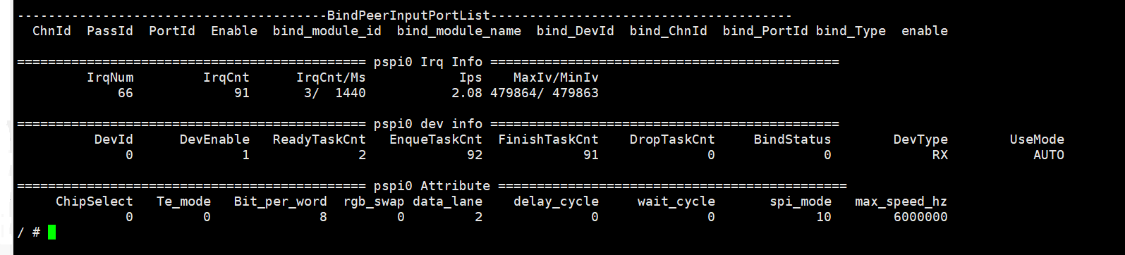
# cat /proc/mi_modules/mi_pspi/mi_pspi0
-
Debugging Information Analysis
Record the current device usage, including interrupt information, device information, and device attributes. It is convenient for users to obtain such information dynamically.
-
Parameter Description
Parameter Describe Irq Info IrqNum interrupt number IrqCnt Count of interrupts generated IrqCnt/Ms Interrupt count within a certain period of time, unit: ms Ips Interrupt count per second MasIv/MinIv The maximum and minimum intervals for completing a task within a certain period of time, unit: ms. Dev Info DevId Device number DevEnable Device enabled status ReadyTaskCnt counts of Ready Task EnqueTaskCnt counts of Enqueue Task FinishTaskCnt counts of Finish Task DropTaskCnt counts of Drop Task BindStatus Bind Status DevType Device Type UseMode Trigger mode Attrbute ChipSelect pspi cs signal Te_mode Enable Te mode or not Bit_per_word Number of bits sent each time rgb_swap Format and datalanes when sending data to the panel data_lane The datalanes for sending data to the panel delay_cycle If SPI_SSCTL has been not setted,it's Delay of two data transfers wait_cycle If SPI_SSCTL has been setted,it's Delay of two data transfers spi_mode device mode Max_speed_hz Maximum clock frequency
5.2. Pspi echo
| Function | Get currently pspi device supported commands |
|---|---|
| Command | echo help > /proc/mi_modules/mi_pspi/mi_pspi0 |
| Parameter Description | NA |
| Example | echo help > /proc/mi_modules/mi_pspi/mi_pspi0 |
| Function | dump frame data |
|---|---|
| Command | echo dumpframe [path] > /proc/mi_modules/mi_pspi/mi_pspi0 |
| Parameter Description | [path] dump data storage path |
| Example | echo dumpframe /mnt/pspiSensorData > /proc/mi_modules/mi_pspi/mi_pspi0 |
6. MODPARAM.json Introduce
Enter the directory sdk/verify/mi_demo/source/pspi/case_json, modify the file reset.sh and adapt the json file:
reset.sh needs to fill in the GPIO INDEX ID of the reset pin.
./gpio.sh -i 67 -w 0
sleep 1
./gpio.sh -i 67 -w 1
ID 67 is PAD_GPIOA_17 which is connected to the panel as the reset pin.
The adaptation of the json file takes dev0_sensor_datalane2_auto.json as an example:
{
    "pspi":[
        {
            "enable":0,   //disable
            "devid" : 0,  //pspi0
            "devtype": "sensor"
        },
        {
            "enable":1,  //enable the panel connected to pspi1
            "devid" : 1, //pspi1
            "devtype": "panel"
        }

    ],

    ......

    "panel":[
        {
            "devId" : 1,
            "autoTrig":1, //Enable auto trig, refresh the screen in real time
            "temode":1, //Enable TE mode, ensure that the screen is not torn
            "datalane":2 //Single-line, dual-line, or quad-line transmission is optional depending on the panel
        },
        {
            "devId" : 0,
            "autoTrig":1,
            "temode":1,
            "datalane":2
        }
    ]

}