Panel Click Program Description
1. Touch Screen Function Scenario Introduction
-
Scenario 1: GUI rotate function demonstration
file -> gfx -> fb -> disp
gfx reads a 480x800 BGRA8888 format file, rotates the image sequentially by 0/90/180/270 degrees and displays it on the GOP via FB, with options for single/double buffer mode.
-
Scenario 2: GUI pattern function demonstration
gfx -> fb -> disp
gfx draws a gradient in green, blue, and red and displays it on the GOP via FB, with options for single/double buffer mode.
2. Compilation Environment Instructions
This is exemplified using the Comake PI D1 development board with the dispcam_pcupid.emmc.glibc-12.4.0-arm-squashfs.comake.pi.d1.1024.dual_sensor.bga_ddr4_riscv_defconfig.
Note
Generally, the corresponding programs have already been packaged on the board by default, so program compilation is not mandatory. You can directly find prog_gfx_gfx_demo in the /customer/sample_code/gfx_gfx_demo folder on the board. If you cannot find the file or have a need to modify the program, you can refer to the following steps.
-
In
project/board/pcupid/COMAKE-PI-D1/config/config_fb.json, change the disp_path parameter to use screen parameters, for example with 720*1280: (The explanation of the following parameters can refer to MI FB API)"fb_device_disp_path": [ { ... "fb_hwlayer_outputcolor": 0, "fb_width": 720, "fb_height": 1280, "fb_timing_width": 720, "fb_timing_height": 1280, "fb_mmap_name": "E_MMAP_ID_FB", "fb_buffer_len": 28800 } ], -
Configure screen dts
Taking the defconfig + mipi screen of Comake PI D1 as an example, add the following content to
kernel/arch/arm/boot/dts/pcupid-comake-pi-d1-dual-sensor-padmux.dtsi:#if 1 // MIPIDSI 4 LANE <PAD_OUTP_CH0 PINMUX_FOR_MIPI_TX_MODE_1 MDRV_PUSE_TX_MIPI_P_CH0>, <PAD_OUTN_CH0 PINMUX_FOR_MIPI_TX_MODE_1 MDRV_PUSE_TX_MIPI_N_CH0>, <PAD_OUTP_CH1 PINMUX_FOR_MIPI_TX_MODE_1 MDRV_PUSE_TX_MIPI_P_CH1>, <PAD_OUTN_CH1 PINMUX_FOR_MIPI_TX_MODE_1 MDRV_PUSE_TX_MIPI_N_CH1>, <PAD_OUTP_CH2 PINMUX_FOR_MIPI_TX_MODE_1 MDRV_PUSE_TX_MIPI_P_CH2>, <PAD_OUTN_CH2 PINMUX_FOR_MIPI_TX_MODE_1 MDRV_PUSE_TX_MIPI_N_CH2>, <PAD_OUTP_CH3 PINMUX_FOR_MIPI_TX_MODE_1 MDRV_PUSE_TX_MIPI_P_CH3>, <PAD_OUTN_CH3 PINMUX_FOR_MIPI_TX_MODE_1 MDRV_PUSE_TX_MIPI_N_CH3>, <PAD_OUTP_CH4 PINMUX_FOR_MIPI_TX_MODE_1 MDRV_PUSE_TX_MIPI_P_CH4>, <PAD_OUTN_CH4 PINMUX_FOR_MIPI_TX_MODE_1 MDRV_PUSE_TX_MIPI_N_CH4>, <PAD_GPIOD_01 PINMUX_FOR_I2C4_MODE_1 MDRV_PUSE_I2C4_SCL>, <PAD_GPIOD_02 PINMUX_FOR_I2C4_MODE_1 MDRV_PUSE_I2C4_SDA>, #endif -
Perform a full package compilation based on the selected defconfig and flash it to the Comake PI D1 board;
-
Navigate to
sdk/verify/sample_codedirectory and executemake clean && make source/pcupid/gfx/gfx_demoto compile; -
Go to
sample_code/out/arm/app/prog_gfx_gfx_demoto obtain the executable file, and place the executable file in the /customer directory on the board;
6.Place the executable file prog_gfx_gfx_demo on the board at the path /customer/sample_code/gfx_gfx_demo and change the permissions to 777.
3. Running Environment Instructions
-
Board-side Environment
COMAKE-PI-D1:
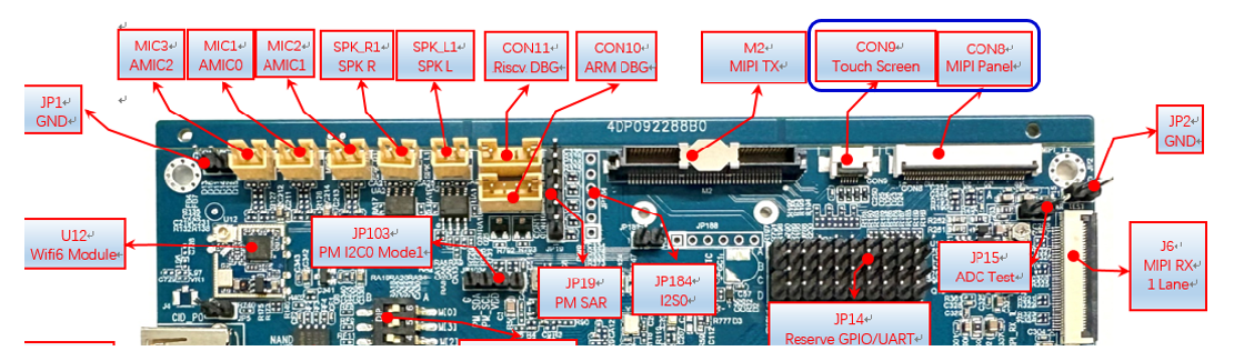
Connecting MIPI screen and touchscreen: Insert the touchscreen and MIPI screen FPC cables into the CON9 and CON8 interfaces on the board.
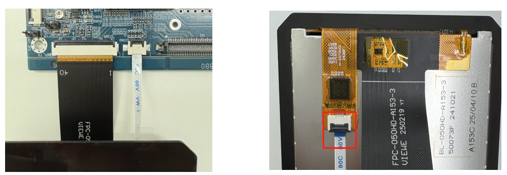
CON8 MIPI screen is connected from above with FPC; ensure not to connect it the wrong way, as shown in the left image below.
For CON9, the FPC is connected from below near the screen side, and from above near the mainboard side; ensure not to connect it incorrectly, as illustrated in the right image below.
Note
If you are using the code package we provided and compiled using the defconfig in this example, then the following bootargs configuration and input files do not need to be executed.
-
bootargs Configuration
Allocate memory separately for the fb from the memory pool, and configure the environment variables in uboot:
setenv bootargs ${bootargs} mma_heap=mma_heap_fb,miu=0,sz=0x1D00000; saveenv;
-
Input Files
Require files under the
source/pcupid/gfx/gfx_demo/resource/input/path;Place the
resourcedirectory alongside the executable file prog_gfx_gfx_demo on the board; the demo will read the following files:./resource/input/480x800.rgb ./resource/input/YUV420SP_320_240.yuv
4. Running Instructions
Execute cd /customer/sample_code/gfx_gfx_demo to navigate to the corresponding file path.
- Command
./prog_gfx_gfx_demo 0 0/1(ttl/mipi) 0/1(single/double buffer)runs scenario 1 gfx rotate function demonstration; -
Command
./prog_gfx_gfx_demo 1 0/1(ttl/mipi) 0/1(single/double buffer)runs scenario 2 gfx pattern function demonstration;Where parameter 1 represents the demo scenario to run, parameter 2 represents the screen type, and parameter 3 represents whether the fb operates in double buffer mode.
To run the rotate scenario, mipi screen, single buffer mode, execute: ./prog_gfx_gfx_demo 0 1 0
5. Running Result Instructions
-
Effect Viewing
After successful execution, both demos will display results on the screen.
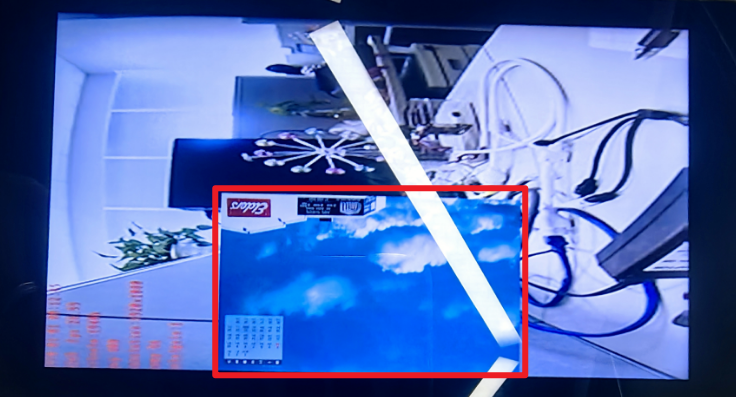
Rotate scenario:
-
Board-side test command
cd /customer/sample_code/gfx_gfx_demo/./prog_gfx_gfx_demo 0 1 0 -
Test Result
The program starts normally. If the platform connects to a screen, you will see the image in the red box spinning in the middle, as shown in the figure below:
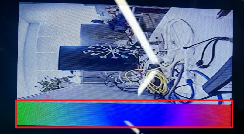
Pattern scenario:
-
Board-side test command
cd /customer/sample_code/gfx_gfx_demo/./prog_gfx_gfx_demo 1 1 0 -
Test Result
The program starts normally. If the platform connects to a screen, you will see the image in the red box moving up from the bottom, as shown in the figure below:
-
-
Exit Command
Enter
qto exit the demo.