KEYPAD USER GUIDE
REVISION HISTORY
| Revision No. | Description |
Date |
|---|---|---|
| 1.0 | 04/18/2024 | |
| 1.1 | 04/11/2025 |
1. Overview
The keypad controller is specially designed to provide flexible and general functions of scanning matrix addressing keyboard. Assuming the keypad is an 8x8 matrix, the principle is that the keypad controller alternately sends scan codes to the 1st to 8th columns of the keypad, and then reads the values from the 1st to 8th rows. Scan one column at a time, and keep scanning the columns. When the keyboard controller detects each key state changed by the row code, there will be a register to maintain the pressed and released state and send an interrupt signal.
2. Functional description
Basic functions:
After pressing a key on the keyboard, the keyboard status can be identified and saved and event events can be reported. When running the user space APP, the corresponding key value will be reported on the serial port, that is, the key being pressed will be identified. Currently, the keyboard supports 3x3, 4x4 or 7x7 keys, but their wiring methods are slightly different. For details, please see 3. Introduction to hardware connection section.
Advanced functions:
Multi-key: The keypad supports multiple keys being pressed and identified at the same time. Currently, up to four keys are supported to be pressed at the same time.
De-jitter: The voltage instability within a certain period of time can be filtered out by filtering.
Mode: You can freely choose the timing of triggering the interrupt, triggering when pressing, triggering when releasing, or triggering when pressing and releasing.
-
Mode 0 generates corresponding interrupts when pressing and releasing.
-
Mode 1 generates a press interrupt when pressing, and no interrupt when releasing.
-
Mode 2 generates a release interrupt when releasing the key, and no interrupt when pressing the key.
-
Mode 3 has three sub-modes, corresponding to the interrupt triggering methods of the first three modes, with only slightly different values stored in the flag bits.
Row and column selection: You can freely select the row and column combination, provided that the number of rows and columns should be less than or equal to the number of padmuxes set, that is, in the case of 3*3, the row and column selection can only be 0/½/3.
3. Introduction to hardware connection
Keypad standard represents the specifications of the keypad, which corresponds to the number of keyboard rows and columns, padmux configuration, and matching gpio status.
| standard | padmux | Specifications (rows * columns) |
|---|---|---|
| 7 | reg_key7x7_mode_1 | 7*7 |
| 72 | reg_key7x7_mode_2 | 7*7 |
| 6 | reg_key6x6_mode_1 | 6*6 |
| 5 | reg_key5x5_mode_1 | 5*5 |
| 52 | reg_key5x5_mode_2 | 5*5 |
| 4 | reg_key4x4_mode_1 | 4*4 |
| 3 | reg_key3x3_mode_1 | 3*3 |
The hardware connection relationship between keypad standard and padmux is as follows:
| standard | padmux | Hardware connection diagram (rows * columns) |
|---|---|---|
| 7|72|6|5 | reg_key7x7_mode_1|reg_key7x7_mode_2| reg_key6x6_mode_1|reg_key5x5_mode_1 |
 |
| 52 | reg_key5x5_mode_2 | 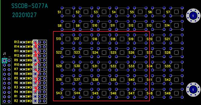 |
| 4 | reg_key4x4_mode_1 | 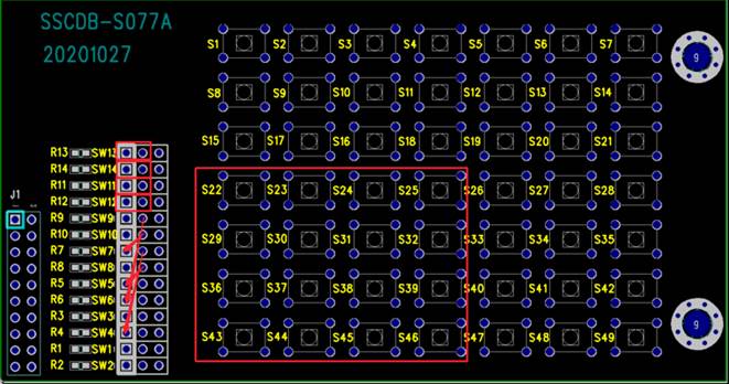 |
| 3 | reg_key3x3_mode_1 | 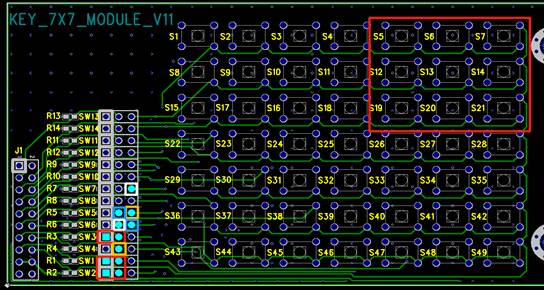 |
4. Introduction to kernel usage
4.1 Kernel config
When compiling the kernel, the configurations that need to be selected are as follows:
    Device Driver-->
        [*] SStar SoC platform drivers-->
            [*] Sstar Keypad driver
    Device Driver-->
        [*] Input device support-->
            [*] Event interface
4.2. Keypad dts configuration
You can set the basic parameters of the driver by configuring the keypad item in dtsi. The parameters of dtsi are shown below:
1.      keypad {
2.          compatible = "sstar,keypad";
3.          reg = <0x0 0x1F201E00 0x0 0x100>;
4.          keypadmode = <0>;
5.          clocks = <&CLK_keypad>;
6.          interrupts=<GIC_SPI INT_IRQ_KEYPAD IRQ_TYPE_LEVEL_HIGH>;
7.          keypad-row1 = <KEY_ESC KEY_8         KEY_W KEY_P          KEY_F           KEY_GRAVE     KEY_N          KEY_SPACE>;
8.          keypad-row2 = <KEY_1   KEY_9         KEY_E KEY_LEFTBRACE  KEY_G           KEY_LEFTSHIFT KEY_M          KEY_CAPSLOCK>;
9.          keypad-row3 = <KEY_2   KEY_0         KEY_R KEY_RIGHTBRACE KEY_H           KEY_BACKSLASH KEY_COMMA      KEY_F1>;
10.         keypad-row4 = <KEY_3   KEY_MINUS     KEY_T KEY_ENTER      KEY_J           KEY_Z         KEY_DOT        KEY_F2>;
11.         keypad-row5 = <KEY_4   KEY_EQUAL     KEY_Y KEY_LEFTCTRL   KEY_K           KEY_X         KEY_SLASH      KEY_F3>;
12.         keypad-row6 = <KEY_5   KEY_BACKSPACE KEY_U KEY_A          KEY_L           KEY_C         KEY_RIGHTSHIFT KEY_F4>;
13.         keypad-row7 = <KEY_6   KEY_TAB       KEY_I KEY_S          KEY_SEMICOLON   KEY_V         KEY_KPASTERISK KEY_F5>;
14.         keypad-row8 = <KEY_7   KEY_Q         KEY_O KEY_D          KEY_APOSTROPHE  KEY_B         KEY_LEFTALT    KEY_F6>;
15.         status = "okay";
16.     };
KEYPAD DTS Description:
| Parameter | Definition | Remark |
|---|---|---|
| reg | Set register bank address | Modification prohibited |
| clocks | Set clk source | Modification prohibited |
| interrupts | Set the irq interrupt number | Modification prohibited |
| keypadmode | Keypad working mode | Mode 0 generates corresponding interrupts when pressing and releasing. Mode 1 generates a press interrupt when pressing, and no interrupt when releasing. Mode 2 generates a release interrupt when releasing the key, and no interrupt when pressing the key. Mode 3 has three sub-modes, corresponding to the interrupt triggering methods of the first three modes, with only slightly different values stored in the flag bits. |
| Keypad-rowX | User-defined key value | The key values corresponding to each row and column of the keypad can be customized according to needs |
4.3. Padmux configuration
Take ssm001a-s01a as an example, open arch/arm64/boot/dts/sstar/pcupid-ssm001a-s01a-padmux.dtsi
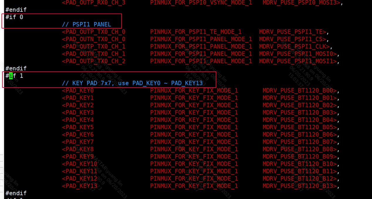
Find the keypad padmux that needs to be configured, and change #if 0 to #if 1, as shown below:
#if 0
                // KEY PAD 7x7 MODE 1
                <PAD_GPIOE_05               PINMUX_FOR_KEY7X7_MODE_1       MDRV_PUSE_KEYPAD77_MODE1_R6>,
                <PAD_GPIOE_06               PINMUX_FOR_KEY7X7_MODE_1       MDRV_PUSE_KEYPAD77_MODE1_R5>,
                <PAD_GPIOE_07               PINMUX_FOR_KEY7X7_MODE_1       MDRV_PUSE_KEYPAD77_MODE1_R4>,
                <PAD_GPIOE_09               PINMUX_FOR_KEY7X7_MODE_1       MDRV_PUSE_KEYPAD77_MODE1_R3>,
                <PAD_GPIOE_10               PINMUX_FOR_KEY7X7_MODE_1       MDRV_PUSE_KEYPAD77_MODE1_R2>,
                <PAD_GPIOE_11               PINMUX_FOR_KEY7X7_MODE_1       MDRV_PUSE_KEYPAD77_MODE1_R1>,
                <PAD_GPIOE_12               PINMUX_FOR_KEY7X7_MODE_1       MDRV_PUSE_KEYPAD77_MODE1_R0>,
                <PAD_GPIOE_13               PINMUX_FOR_KEY7X7_MODE_1       MDRV_PUSE_KEYPAD77_MODE1_S0>,
                <PAD_GPIOE_14               PINMUX_FOR_KEY7X7_MODE_1       MDRV_PUSE_KEYPAD77_MODE1_S1>,
                <PAD_GPIOE_15               PINMUX_FOR_KEY7X7_MODE_1       MDRV_PUSE_KEYPAD77_MODE1_S2>,
                <PAD_GPIOE_16               PINMUX_FOR_KEY7X7_MODE_1       MDRV_PUSE_KEYPAD77_MODE1_S3>,
                <PAD_GPIOE_17               PINMUX_FOR_KEY7X7_MODE_1       MDRV_PUSE_KEYPAD77_MODE1_S4>,
                <PAD_GPIOE_18               PINMUX_FOR_KEY7X7_MODE_1       MDRV_PUSE_KEYPAD77_MODE1_S5>,
                <PAD_GPIOE_19               PINMUX_FOR_KEY7X7_MODE_1       MDRV_PUSE_KEYPAD77_MODE1_S6>,
#endif
#if 0
                // KEY PAD 7x7 MODE 2
                <PAD_GPIOA_12               PINMUX_FOR_KEY7X7_MODE_2       MDRV_PUSE_KEYPAD77_MODE2_R6>,
                <PAD_GPIOA_13               PINMUX_FOR_KEY7X7_MODE_2       MDRV_PUSE_KEYPAD77_MODE2_R5>,
                <PAD_GPIOA_14               PINMUX_FOR_KEY7X7_MODE_2       MDRV_PUSE_KEYPAD77_MODE2_R4>,
                <PAD_GPIOA_15               PINMUX_FOR_KEY7X7_MODE_2       MDRV_PUSE_KEYPAD77_MODE2_R3>,
                <PAD_GPIOA_16               PINMUX_FOR_KEY7X7_MODE_2       MDRV_PUSE_KEYPAD77_MODE2_R2>,
                <PAD_GPIOA_17               PINMUX_FOR_KEY7X7_MODE_2       MDRV_PUSE_KEYPAD77_MODE2_R1>,
                <PAD_GPIOA_18               PINMUX_FOR_KEY7X7_MODE_2       MDRV_PUSE_KEYPAD77_MODE2_R0>,
                <PAD_GPIOA_19               PINMUX_FOR_KEY7X7_MODE_2       MDRV_PUSE_KEYPAD77_MODE2_S0>,
                <PAD_GPIOB_00               PINMUX_FOR_KEY7X7_MODE_2       MDRV_PUSE_KEYPAD77_MODE2_S1>,
                <PAD_GPIOB_01               PINMUX_FOR_KEY7X7_MODE_2       MDRV_PUSE_KEYPAD77_MODE2_S2>,
                <PAD_GPIOB_02               PINMUX_FOR_KEY7X7_MODE_2       MDRV_PUSE_KEYPAD77_MODE2_S3>,
                <PAD_GPIOB_03               PINMUX_FOR_KEY7X7_MODE_2       MDRV_PUSE_KEYPAD77_MODE2_S4>,
                <PAD_GPIOB_04               PINMUX_FOR_KEY7X7_MODE_2       MDRV_PUSE_KEYPAD77_MODE2_S5>,
                <PAD_GPIOB_05               PINMUX_FOR_KEY7X7_MODE_2       MDRV_PUSE_KEYPAD77_MODE2_S6>,
#endif
#if 0
                // KEY PAD 6x6 MODE 1
                <PAD_GPIOE_06               PINMUX_FOR_KEY6X6_MODE_1       MDRV_PUSE_KEYPAD66_MODE1_R5>,
                <PAD_GPIOE_07               PINMUX_FOR_KEY6X6_MODE_1       MDRV_PUSE_KEYPAD66_MODE1_R4>,
                <PAD_GPIOE_09               PINMUX_FOR_KEY6X6_MODE_1       MDRV_PUSE_KEYPAD66_MODE1_R3>,
                <PAD_GPIOE_10               PINMUX_FOR_KEY6X6_MODE_1       MDRV_PUSE_KEYPAD66_MODE1_R2>,
                <PAD_GPIOE_11               PINMUX_FOR_KEY6X6_MODE_1       MDRV_PUSE_KEYPAD66_MODE1_R1>,
                <PAD_GPIOE_12               PINMUX_FOR_KEY6X6_MODE_1       MDRV_PUSE_KEYPAD66_MODE1_R0>,
                <PAD_GPIOE_13               PINMUX_FOR_KEY6X6_MODE_1       MDRV_PUSE_KEYPAD66_MODE1_S0>,
                <PAD_GPIOE_14               PINMUX_FOR_KEY6X6_MODE_1       MDRV_PUSE_KEYPAD66_MODE1_S1>,
                <PAD_GPIOE_15               PINMUX_FOR_KEY6X6_MODE_1       MDRV_PUSE_KEYPAD66_MODE1_S2>,
                <PAD_GPIOE_16               PINMUX_FOR_KEY6X6_MODE_1       MDRV_PUSE_KEYPAD66_MODE1_S3>,
                <PAD_GPIOE_17               PINMUX_FOR_KEY6X6_MODE_1       MDRV_PUSE_KEYPAD66_MODE1_S4>,
                <PAD_GPIOE_18               PINMUX_FOR_KEY6X6_MODE_1       MDRV_PUSE_KEYPAD66_MODE1_S5>,
#endif
#if 0
                // KEY PAD 5x5 MODE 1
                <PAD_GPIOE_07               PINMUX_FOR_KEY5X5_MODE_1       MDRV_PUSE_KEYPAD55_MODE1_R4>,
                <PAD_GPIOE_09               PINMUX_FOR_KEY5X5_MODE_1       MDRV_PUSE_KEYPAD55_MODE1_R3>,
                <PAD_GPIOE_10               PINMUX_FOR_KEY5X5_MODE_1       MDRV_PUSE_KEYPAD55_MODE1_R2>,
                <PAD_GPIOE_11               PINMUX_FOR_KEY5X5_MODE_1       MDRV_PUSE_KEYPAD55_MODE1_R1>,
                <PAD_GPIOE_12               PINMUX_FOR_KEY5X5_MODE_1       MDRV_PUSE_KEYPAD55_MODE1_R0>,
                <PAD_GPIOE_13               PINMUX_FOR_KEY5X5_MODE_1       MDRV_PUSE_KEYPAD55_MODE1_S0>,
                <PAD_GPIOE_14               PINMUX_FOR_KEY5X5_MODE_1       MDRV_PUSE_KEYPAD55_MODE1_S1>,
                <PAD_GPIOE_15               PINMUX_FOR_KEY5X5_MODE_1       MDRV_PUSE_KEYPAD55_MODE1_S2>,
                <PAD_GPIOE_16               PINMUX_FOR_KEY5X5_MODE_1       MDRV_PUSE_KEYPAD55_MODE1_S3>,
                <PAD_GPIOE_17               PINMUX_FOR_KEY5X5_MODE_1       MDRV_PUSE_KEYPAD55_MODE1_S4>,
#endif
#if 0
                // KEY PAD 5x5 MODE 2
                <PAD_GPIOE_09               PINMUX_FOR_KEY5X5_MODE_2       MDRV_PUSE_KEYPAD55_MODE2_R4>,
                <PAD_GPIOE_10               PINMUX_FOR_KEY5X5_MODE_2       MDRV_PUSE_KEYPAD55_MODE2_R3>,
                <PAD_GPIOE_11               PINMUX_FOR_KEY5X5_MODE_2       MDRV_PUSE_KEYPAD55_MODE2_R2>,
                <PAD_GPIOE_12               PINMUX_FOR_KEY5X5_MODE_2       MDRV_PUSE_KEYPAD55_MODE2_R1>,
                <PAD_GPIOE_13               PINMUX_FOR_KEY5X5_MODE_2       MDRV_PUSE_KEYPAD55_MODE2_R0>,
                <PAD_GPIOE_14               PINMUX_FOR_KEY5X5_MODE_2       MDRV_PUSE_KEYPAD55_MODE2_S0>,
                <PAD_GPIOE_15               PINMUX_FOR_KEY5X5_MODE_2       MDRV_PUSE_KEYPAD55_MODE2_S1>,
                <PAD_GPIOE_16               PINMUX_FOR_KEY5X5_MODE_2       MDRV_PUSE_KEYPAD55_MODE2_S2>,
                <PAD_GPIOE_17               PINMUX_FOR_KEY5X5_MODE_2       MDRV_PUSE_KEYPAD55_MODE2_S3>,
                <PAD_GPIOE_18               PINMUX_FOR_KEY5X5_MODE_2       MDRV_PUSE_KEYPAD55_MODE2_S4>,
#endif
#if 0
                // KEY PAD 4x4 MODE 1
                <PAD_GPIOA_18               PINMUX_FOR_KEY4X4_MODE_1      MDRV_PUSE_KEYPAD44_MODE1_R3>,
                <PAD_GPIOA_19               PINMUX_FOR_KEY4X4_MODE_1      MDRV_PUSE_KEYPAD44_MODE1_R2>,
                <PAD_GPIOB_00               PINMUX_FOR_KEY4X4_MODE_1      MDRV_PUSE_KEYPAD44_MODE1_R1>,
                <PAD_GPIOB_01               PINMUX_FOR_KEY4X4_MODE_1      MDRV_PUSE_KEYPAD44_MODE1_R0>,
                <PAD_GPIOB_02               PINMUX_FOR_KEY4X4_MODE_1      MDRV_PUSE_KEYPAD44_MODE1_S0>,
                <PAD_GPIOB_03               PINMUX_FOR_KEY4X4_MODE_1      MDRV_PUSE_KEYPAD44_MODE1_S1>,
                <PAD_GPIOB_04               PINMUX_FOR_KEY4X4_MODE_1      MDRV_PUSE_KEYPAD44_MODE1_S2>,
                <PAD_GPIOB_05               PINMUX_FOR_KEY4X4_MODE_1      MDRV_PUSE_KEYPAD44_MODE1_S3>,
#endif
#if 0
                // KEY PAD 3x3 MODE 1
                <PAD_GPIOA_12                PINMUX_FOR_KEY3X3_MODE_1      MDRV_PUSE_KEYPAD33_MODE1_R2>,
                <PAD_GPIOA_13                PINMUX_FOR_KEY3X3_MODE_1      MDRV_PUSE_KEYPAD33_MODE1_R1>,
                <PAD_GPIOA_14                PINMUX_FOR_KEY3X3_MODE_1      MDRV_PUSE_KEYPAD33_MODE1_R0>,
                <PAD_GPIOA_15                PINMUX_FOR_KEY3X3_MODE_1      MDRV_PUSE_KEYPAD33_MODE1_S0>,
                <PAD_GPIOA_16                PINMUX_FOR_KEY3X3_MODE_1      MDRV_PUSE_KEYPAD33_MODE1_S1>,
                <PAD_GPIOA_17                PINMUX_FOR_KEY3X3_MODE_1      MDRV_PUSE_KEYPAD33_MODE1_S2>,
#endif
The first column is the pin index number, which can be found in drivers/sstar/inlcude/{chipname}/gpio.h;
The second column is the mode definition. In the hal_gpio_st_padmux_info array in drivers/sstar/gpio/{chipname}/hal_pinmux.c, the multiplexing relationship of all pins is listed. You can query the array to check which multiplexing functions the pin supports;
The third column is the index name of the pin and the matching mode, which can be found in drivers/sstar/include/drv_puse.h.
4.4. Introduction to module usage
4.4.1. Sample code
Demo location: kernel/drivers/sstar/keypad/verify/key.c
-
cat /proc/bus/input/devices to get which input node the keypad is mounted on
-
Capture event information by polling the dev/input/event node
1.  int main(int argc, char *argv[])
2.  {
3.      int                fd;
4.      struct input_event ev_key;
5.      if (argc != 3 && argc != 2)
6.      {
7.          printf("Usage:\n");
8.          printf("%s /dev/input/event0 or /dev/input/event1 + enable\n", argv[0]);
9.          return 0;
10.     }
11.     fd = open(argv[1], O_RDWR);
12.     if (fd < 0)
13.     {
14.         perror("open device buttons");
16.         exit(1);
17.     }
18.     if (argc == 3)
19.     {
20.         if (strcmp("enable", argv[2]) == 0)
21.         {
22.             test_key1(fd, &ev_key);
23.             test_key2(fd, &ev_key);
24.             test_key3(fd, &ev_key);
25.         }
26.         else
27.         {
28.             printf("%s /dev/input/event0 or /dev/input/event1 + enable\n", argv[0]);
29.             return 0;
30.         }
31.     }
32.     else if (argc == 2)
33.     {
34.         printf("enter normal mode\n");
35.         while (1)
36.         {
37.             read(fd, &ev_key, sizeof(struct input_event));
38.             printf("type:%d,code:%d,value:%d\n", ev_key.type, ev_key.code, ev_key.value);
39.         }
40.     }
41.     close(fd);
42.     return 0;
43. }
Compile method:
arm-linux-gnueabihf-gcc -o key key.c; //Compile application
Usage method:
./key /dev/input/event0 or /dev/input/event1 + enable
Parameter 1: Select keypad input event node
Parameter 2 (optional): enable means to enter test mode
eg1.
./key /dev/input/event0
Key events will be captured and output in the terminal.
eg2.
./key /dev/input/event0 enable
Test whether the functions of pressing a single button, pressing two buttons at the same time, and pressing three buttons at the same time are normal.
Need to be repeated in the following order
-
Press all 49 single buttons
-
Press 8 groups of double buttons
-
Press 4 groups of three buttons
After the above three tasks are completed, the test program will exit normally
4.4.2. Cmd method to change parameters
The keypad debug method mainly uses the registered node to change the parameters to achieve the purpose of testing different functions.
pcupid: /sys/bus/platform/devices/1f201e00.keypad/
Echo the corresponding parameters to the node named keypad in the corresponding path to change the corresponding parameters and complete the parameters.
4.4.2.1
Command: echo mode=X > keypad
X: 0 or 1 or 2 or 3
This command is used to control the mode of the keypad. For details of the specific mode, see 4.2. Keypad dts configuration. In short, it can control the interrupt triggering mode of the keypad.
4.4.2.2 clk
Command: echo clk=X > keypad
X: 0 or 1
This command is used to control the switch of the keypad clock, and its clock frequency is fixed at 12M. When clk=1, the keypad clock is enabled; when clk=0, the keypad clock is turned off.
4.4.2.3 debounce
Command: echo debounce=X > keypad
X: Any integer value greater than 0, the default value is 14, and the maximum value does not exceed 255.
This command is used to control the duration of the keypad's de-jitter filter. The principle is to set the number of cycles of the filter to determine its duration, and the shortest is not less than one cycle.
4.4.2.4 glhrmclk
Command: echo glhrmclk=X > keypad
X: Any integer value greater than 0, the maximum value does not exceed 12000000, the default value is 32000, and it is recommended to set the adjacent order of magnitude.
This command is used to control the frequency of the keypad de-jitter filter, the maximum is the keypad clock frequency 12M. Together with the number of cycles, it determines the length of the debounce time.
4.4.2.5 scanclk
Command: echo scanclk=X > keypad
X: Any integer value greater than 0, the maximum value does not exceed 12000000, the default value is 32000, and it is recommended to set the adjacent order of magnitude.
This command is used to control the scan rate of the keypad, the maximum is its clock frequency 12M. The scan frequency divided by the number of scan pins used is the low level duration of each pin, and the key recognition is triggered by the low level.
4.4.2.6 force
Command: echo force=X > keypad
X: 0 or 1
This command is used to control the keypad's force interrupt switch. During testing, you can use this method to force the IP to trigger an interrupt when the key is not pressed. Force trigger when set to 1; turn it off when set to 0.
4.4.2.7 dbg
Command: echo dbg=X > keypad
X: 0 or 1
This command is used to control the keypad's debug message printing. Set it to 1 to turn it on, and set it to 0 to turn it off.
4.4.2.8 submode
Command: echo submode=X > keypad
X: 0 or 1 or 2
This command is used to control the three sub-modes of mode3 of the keypad. For specific mode information, see 4.2. Keypad dts configuration.
4.4.2.9 row
Command: echo row=X > keypad
X: 0 or 1 or 2 or 3 or 4 or 5 or 6 or 7
This command is used to control the number of rows of the keypad. It can control the number of rows that the keypad responds to. The maximum value depends on the padmux mode. For example, if padmux is 3*3, it is meaningless to set the number of rows to 4. The maximum value can only be set to 3.
4.4.2.10 col
Command: echo col=X > keypad
X: 0 or 1 or 2 or 3 or 4 or 5 or 6 or 7
This command is used to control the number of columns of the keypad, which can control the number of columns and rows that the keypad responds to. The maximum value depends on the padmux mode. For example, if padmux is 3*3, it is meaningless to set the number of columns to 4, and the maximum value can only be set to 3.
4.4.2.11 align
Command: echo align=X > keypad
X: Any integer value greater than 0, generally set in the range of 42ms~170ms
This command is used to control the synchronization time of the keypad, and is used to control the recognition time of multiple keys pressed simultaneously.
4.4.2.12 standard
Command: echo standard=X > keypad
X: See the Standard table in Chapter 2
This command is used to control the keypad Standard, and can also control the number of rows and columns and gpio status and other matrix keyboard properties (excluding padmux).
5. FAQ
Decide according to the actual module situation:
Q1: How to eliminate the repeated triggering of KEYPAD keys
Due to differences in hardware environments, the debounce capability of keypad on some hardware platforms is insufficient, which is specifically manifested as multiple feedbacks after pressing once. This problem can be solved by configuring the debounce circuit parameters inside the keypad to reduce the probability of jitter.
-
Use the command to increase the debounce coefficient of the keypad:
echo debounce=X > keypad
X: Any integer value greater than 0, the default value is 14, and the maximum value does not exceed 255.
This command is used to control the duration of the keypad's debounce filter. The principle is to set the number of cycles of the filter to determine its duration, and the shortest is not less than one cycle.
-
If the effect is not obvious after setting 1 to the highest value, you can further use the following command:
echo glhrmclk=X > keypad
Reduce the frequency of the keypad debounce filter.
X: Any integer value greater than 0, the default value is 32000, the maximum value does not exceed 12000000, and it is recommended to set adjacent orders of magnitude.
This command is used to control the frequency of the keypad debounce filter, the maximum is the keypad clock frequency 12M. Together with the number of cycles, it determines the length of the debounce time.
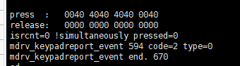
Q2: The keypad has an interrupt but no event and there is an abnormal value in the reg_key_final_status register
Observe the initialization log and find that there is an abnormal value in the reg_key_final_status register after initialization. This abnormality may be caused by unstable level.
Observe the schematic diagram. The key0 network and the KEY0_USB3 network are connected by a 0 ohm resistor, and KEY0_USB3 is pulled down to the ground, which affects the normal waveform of read and causes abnormal data in the keypad's reg_key_final_status register.
The key events press and release exist in pairs. The abnormal waveform causes the key event to not be reset normally, so no new event is generated.
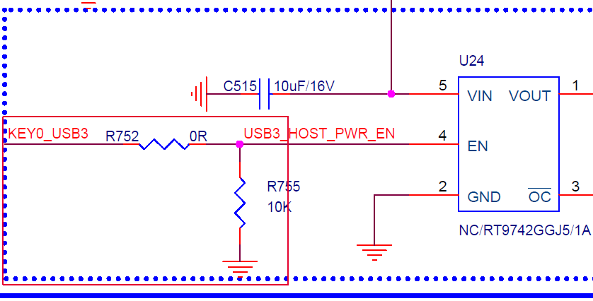
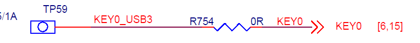
The pull-down resistor affects the waveform of KEY0, causing the event to fail to be reported normally.
Remove R754 to eliminate the pull-down effect.
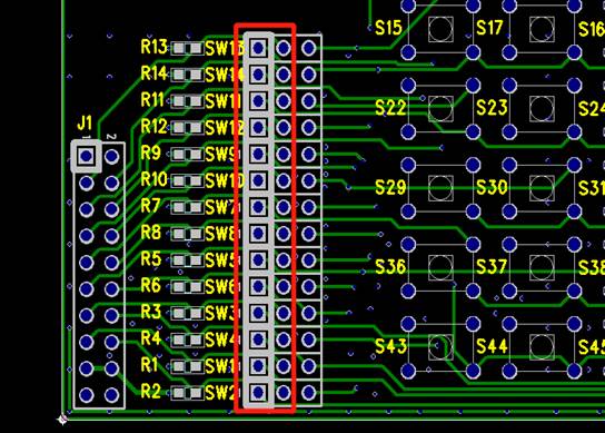
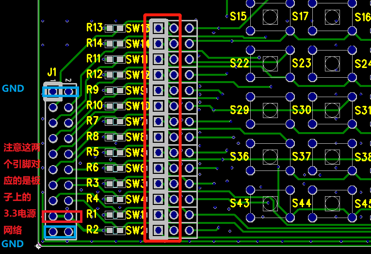
Q3: Determine the line sequence of the keypad board
Hardware board making may not consider the insertion direction of the keypad. If the wrong direction is inserted, some rows and columns of keys may not respond, and the growth order of the key code will change from left to right to top to bottom.
Method to determine the direction
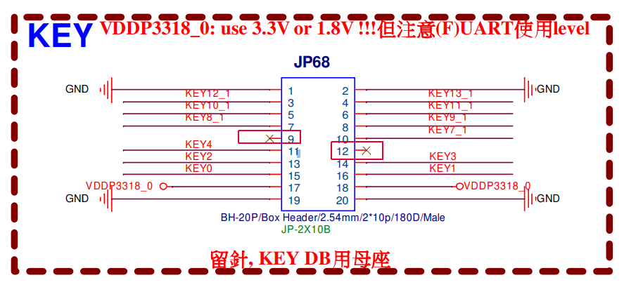
Test the voltage distribution of the keypad interface on the board. The four pins at both ends are gnd. The position marked in the figure is 3.3. The direction can be determined by measuring the position of 3.3 on the motherboard.
Q4: Some rows and columns of keys do not respond
Reason 1: Pins are not brought out
The keypad port on some interfaces is not brought out completely, which may also cause some rows and columns of keys to not respond. For example, 9 and 12 are suspended in the figure below, and key5 and key6 are not brought out, resulting in two missing rows of keypad.
Check the schematic
Reason 2: PADMUX occupied
The priority of the keypad is not high, and the pins are easily occupied. The more obvious feature is that the waveforms of some pins are abnormal, such as other communication protocols
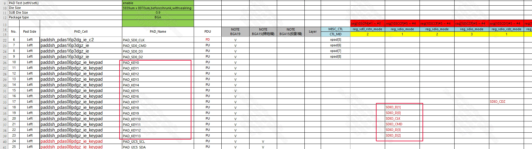
Check the table {chipname}tmux_test.xlsm
7*7 The pins used by KEYPAD are PAD_KEY0-PAD_KEY13. Check whether there are other modules occupying the padmux. This module may affect the keypad, such as the SDIO in the figure.
Method 1:
Check whether the padmux of the corresponding module is enabled, edit the padmux.dtsi of the corresponding board, and change all the occupied configurations to #if 0
Method 2:
If the above method does not work, you can directly disable all suspected padmuxes in the padmux register, and then check which module is the cause.