RISCV_CAPTURE USER GUIDE
REVISION HISTORY
| Revision No. | Description |
Date |
|---|---|---|
| 1.0 | 04/09/2025 |
1. OVERVIEW
1.1. Capture
Capture can capture PWM waveform information, including period, duty cycle and number of pulses. The principle of Capture is to obtain the PWM waveform information by capturing the rising and falling edges of the PWM waveform and their time intervals. It should be noted that the captured waveform duty cycle range should be 0% < duty < 100%, because when the duty cycle is 0% or 100%, there is no rising and falling edge, and the jump cannot be captured to obtain the input PWM waveform information.
The clock frequency of Capture is 24Mhz, and switching is not supported.
1.2. channel
Capture has 8 groups, of which the first 4 groups have 2 channels each, and the last 4 groups have 1 channel each, there are 12 channels to support capture in total.
Capture supports up to 12 channels to capture PWM period and duty cycle at the same time, but each group has only 1 channel to capture the number of pulses, so it supports up to 8 channels to capture the number of pulses at the same time.
2. Key Words
sysdesc:
RTOS files used to describe the hardware attributes of peripherals. The attribute values contained in the peripheral node can be used to configure the peripherals, similar to the device tree file of Linux.
padmux:
Pin Multiplexing, used to connect the functional pins of a module to specific external pins, thereby establishing signal connections.
deglitch:
Glitch filtering: waveforms shorter than the deglitch value (in ns) will be ignored. The setting of deglitch affects the upper limit of the captured PWM frequency
3. Function Description
Support three modes of pulse number capture: normal mode, direction mode, quad mode.the captured frequency range is 1Hz ~ 6MHz.
3.1. Pulse Counting Mode--Normal Mode
All 8 capture groups support normal mode. After capturing two rising edges, the count increases by 1. The maximum value is 0xFFFF, and overflow is cleared to 0.
3.2. Pulse Counting Mode--Direction Mode
Only the first 4 groups Capture0-Capture3 support direction mode. Each group has two channels, one for pulse counting and the other for direction judgment.
When the channel as the direction captures a high level, the pulse count starts to increase, the maximum value is 0xFFFF, and overflow is cleared to 0.
When the channel as the direction captures a low level, the pulse count starts to decrease, the maximum value is 0xFFFF, gradually decreases to 0 and then jumps to 0xFFFF, repeating the cycle.
3.3. Pulse Counting Mode--Quad Mode
The quad mode is also called orthogonal encoding counting mode. It is only supported by the first 4 groups Capture0-Capture3, with two channels in each group.
By capturing PWM signals with the same signal and a phase difference of 90 degrees (i.e. orthogonal signals), the number and direction of pulses are calculated.
As shown in the figure, quad mode means 4 times counting. The number of pulses will be increased by 1 only when the counting at the 4 moments in the figure is met, so it has a higher counting accuracy.
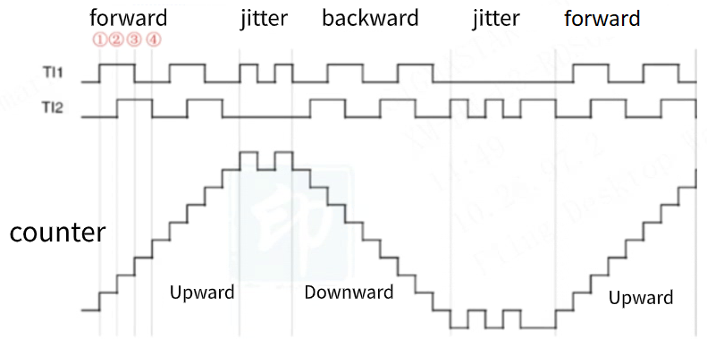
As shown in the figure, pulses count on both edges of TI1 and TI2, among which,
Moment 1: TI2 is at a low level, TI1 has an upward edge transition, the counter counts up
Moment 2: TI1 is at a high level, TI2 has an upward edge transition, the counter continues to count up
Moment 3: TI2 is at a high level, TI1 has a downward edge transition, the counter continues to count up
Moment 4: TI1 is at a low level, TI2 has a downward edge transition, the counter continues to count up
4. RISCV USAGE INTRODUCTION
4.1. Driver Path
sc/driver/sysdriver/capture/os/capture_os.h
sc/driver/sysdriver/capture/drv/pub/drv_capture.h
sc/driver/sysdriver/capture/drv/src/drv_capture.c
sc/driver/sysdriver/capture/drv/src/drv_capture_test.c
sc/driver/sysdriver/capture/hal/chipname/src/hal_capture.c
sc/driver/sysdriver/capture/hal/chipname/inc/hal_capture.h
sc/driver/sysdriver/capture/hal/chipname/inc/hal_capture_cfg.h
4.2. CONFIG Configuration
The config file is located at mak/options_chipname_riscv_isw.mak, enable CONFIG_CAPTURE_SUPPORT.
# Feature_Name = [DRV] CAPTURE driver support
# Description = CAPTURE driver support
# Option_Selection = TRUE, FALSE
CONFIG_CAPTURE_SUPPORT = TRUE
4.3. SYSDESC Configuration
The chipname-default.sys file is located in sc\driver\sysdriver\sysdesc\hal\pcupid\pub\.
<capture0>
    [reg_u32] 0x22CE000;
    [interrupts_u32] INT_IRQ_CAPTURE;
    [camclk_u16] CAMCLK_pwm_capture;
    [channel_u8] 0, 1;
    [pulse_cal_mode_u8] 0;
    [pulse_cal_chan_u8] 0;
    [deglitch_u32] 0;
    [status_u8] 0;

......

<capture7>
    [reg_u32] 0x22CF980;
    [interrupts_u32] INT_IRQ_CAPTURE;
    [camclk_u16] CAMCLK_pwm_capture;
    [channel_u8] 11;
    [pulse_cal_mode_u8] 0;
    [pulse_cal_chan_u8] 11;
    [deglitch_u32] 0;
    [padmux_u16] PINMUX_FOR_UNKNOWN_MODE;
    [status_u8] 0;
The attributes supported for configuration in the driver are as follows:
| Attribute | Description | Setting Value | Remark |
|---|---|---|---|
| reg_u32 | Set the address of the register bank | / | Modification prohibited |
| interrupts_u32 | Specify the hardware interrupt number to be used | INT_IRQ_CAPTURE | Modification prohibited |
| camclk_u16 | Specify the clock source to be used | CAMCLK_pwm_capture | Modification prohibited |
| channel_u8 | Channel ID owned by each group | / | Modification prohibited |
| pulse_cal_mode_u8 | Select different pulse counting modes, please refer to Pulse Counting Mode Description | Capture0~3 supports 0->normal, 1->quad, 2->dir, Capture4~7 only supports 0: normal | Can be modified as needed |
| pulse_cal_chan_u8 | Select the channel for capturing the number of pulses | Capture0~3 supports 2-choose-1, Capture4~7 only supports 1 channel | Can be modified as needed |
| deglitch_u32 | Set the pulse to be filtered | In ns, for example, if the setting value is 7, then pulses with a high level duration shorter than 24M * 7 = 291.67ns cannot be captured | Can be modified as needed |
| status | Select whether to enable the Capture driver | 1: enable; 0: disable | Can be modified as needed |
4.4. PADMUX Configuration
CONFIG Configuration: CONFIG_PADMUX_SUPPORT=TRUE
If the chipname_xxx.sys file is configured with the attribute <padmux>, then the PADMUX setting is directly configured here:
<padmux>
    [schematic_u32_u32_u32]
            PAD_OUTP_CH0   PINMUX_FOR_PWMIN0_MODE_1 MDRV_PUSE_PWMIN0,
            PAD_OUTN_CH0   PINMUX_FOR_PWMIN1_MODE_1 MDRV_PUSE_PWMIN1,
            PAD_OUTP_CH1   PINMUX_FOR_PWMIN2_MODE_1 MDRV_PUSE_PWMIN2,
            PAD_OUTN_CH1   PINMUX_FOR_PWMIN3_MODE_1 MDRV_PUSE_PWMIN3,
            PAD_OUTP_CH2   PINMUX_FOR_PWMIN4_MODE_1 MDRV_PUSE_PWMIN4,
            PAD_OUTN_CH2   PINMUX_FOR_PWMIN5_MODE_1 MDRV_PUSE_PWMIN5,
            PAD_OUTP_CH3   PINMUX_FOR_PWMIN6_MODE_1 MDRV_PUSE_PWMIN6,
            PAD_OUTN_CH3   PINMUX_FOR_PWMIN7_MODE_1 MDRV_PUSE_PWMIN7,
            PAD_GPIOE_10   PINMUX_FOR_PWMIN8_MODE_3 MDRV_PUSE_PWMIN8,
            PAD_GPIOD_00   PINMUX_FOR_PWMIN9_MODE_2 MDRV_PUSE_PWMIN9,
            PAD_GPIOE_14   PINMUX_FOR_PWMIN10_MODE_3 MDRV_PUSE_PWMIN10,
            PAD_GPIOE_16   PINMUX_FOR_PWMIN11_MODE_3 MDRV_PUSE_PWMIN11;
    [status_u8] 1;
Otherwise, by enabling the PADMUX driver, configure the pin multiplexing function in the chipname-xxx-padmux.c file, which is located in sc/driver/sysdriver/padmux/hal/chipname/src. You only need to add the following content to the corresponding schematic attribute:
pad_info_t schematic[] =
{
    {PAD_OUTP_CH0   PINMUX_FOR_PWMIN0_MODE_1 MDRV_PUSE_PWMIN0},
    {PAD_OUTN_CH0   PINMUX_FOR_PWMIN1_MODE_1 MDRV_PUSE_PWMIN1},
    {PAD_OUTP_CH1   PINMUX_FOR_PWMIN2_MODE_1 MDRV_PUSE_PWMIN2},
    {PAD_OUTN_CH1   PINMUX_FOR_PWMIN3_MODE_1 MDRV_PUSE_PWMIN3},
    {PAD_OUTP_CH2   PINMUX_FOR_PWMIN4_MODE_1 MDRV_PUSE_PWMIN4},
    {PAD_OUTN_CH2   PINMUX_FOR_PWMIN5_MODE_1 MDRV_PUSE_PWMIN5},
    {PAD_OUTP_CH3   PINMUX_FOR_PWMIN6_MODE_1 MDRV_PUSE_PWMIN6},
    {PAD_OUTN_CH3   PINMUX_FOR_PWMIN7_MODE_1 MDRV_PUSE_PWMIN7},
    {PAD_GPIOE_10   PINMUX_FOR_PWMIN8_MODE_3 MDRV_PUSE_PWMIN8},
    {PAD_GPIOD_00   PINMUX_FOR_PWMIN9_MODE_2 MDRV_PUSE_PWMIN9},
    {PAD_GPIOE_14   PINMUX_FOR_PWMIN10_MODE_3 MDRV_PUSE_PWMIN10},
    {PAD_GPIOE_16   PINMUX_FOR_PWMIN11_MODE_3 MDRV_PUSE_PWMIN11},
};
The first column is the pin index number, which can be queried in sc/drivers/sysdriver/gpio/hal/chipname/pub/gpio.h;
The second column is the mode definition, which can be queried in sc/drivers/sysdriver/gpio/hal/chipname/pub/padmux.h;
The third column is the index name of the pin and matching mode, which can be queried in sc/drivers/sysdriver/padmux/drv/pub/drv_puse.h;
4.5 Demo code
The demo code is located in sc/driver/sysdriver/capture/drv/src/drv_capture_test.c.
#include <drv_capture.h>
#include <sys_sys_isw_cli.h>

#if defined(__VER_CAPTURE__)

static capture_cb_t cb_t[12] = {0};

int capture_bound(void *para)
{
    u8 group;

    group = *((u8 *)para);

    cliPrintf("capture%hhu pulse exceeding bound\n", group);

    return 0;
}

static int capture_ut_test(CLI_t *cli, char *p)
{
    int                   ret;
    char *                cmd;
    u32                   edge;
    u32                   group;
    u32                   enable;
    u32                   channel;
    u64                   time_ns;
    struct capture_info   info    = {0};
    struct capture_config cap_cfg = {0};

    cmd = CliTokenPop(cli);
    if (!cmd)
        return -eCLI_PARSE_INPUT_ERROR;

    if (strcmp(cmd, "config") == 0)
    {
        if (CliTokenCount(cli) == 4)
        {
            if (CliTokenPopNum(cli, &group, 0) != eCLI_PARSE_OK)
                goto cap_config_msg;
            if (CliTokenPopNum(cli, &channel, 0) != eCLI_PARSE_OK)
                goto cap_config_msg;
            if (CliTokenPopNum(cli, &edge, 0) != eCLI_PARSE_OK)
                goto cap_config_msg;
            if (CliTokenPopNum(cli, &enable, 0) != eCLI_PARSE_OK)
                goto cap_config_msg;

            cb_t[channel] = capture_bound;
            if (enable)
                drv_capture_register_callback((u8)group, cb_t[channel]);
            else
                drv_capture_unregister_callback((u8)group, cb_t[channel]);

            cap_cfg.group       = (u8)group;
            cap_cfg.channel     = (u8)channel;
            cap_cfg.cap_edge    = (u8)edge;
            cap_cfg.pul_edge    = (u8)edge;
            cap_cfg.cap_enable  = (u8)enable;
            cap_cfg.pul_enable  = (u8)enable;
            cap_cfg.quad_pul_up = 20000;
            cap_cfg.quad_pul_dn = 20000;
            cap_cfg.timeout     = 0;

            ret = drv_capture_set_config(&cap_cfg);
            if (ret)
                return -eCLI_PARSE_INVALID_PARAMETER;
        }
        else
        {
        cap_config_msg:
            cliPrintf("command format : capture <config> [group] [channel] [edge] [enable]\n");
            return -eCLI_PARSE_INVALID_PARAMETER;
        }

        return eCLI_PARSE_OK;
    }
    else if (strcmp(cmd, "period") == 0)
    {
        if (CliTokenCount(cli) == 2)
        {
            if (CliTokenPopNum(cli, &group, 0) != eCLI_PARSE_OK)
                goto cap_period_msg;
            if (CliTokenPopNum(cli, &channel, 0) != eCLI_PARSE_OK)
                goto cap_period_msg;

            info.group   = (u8)group;
            info.channel = (u8)channel;

            ret = drv_capture_period(&info);
            if (ret)
                return -eCLI_PARSE_INVALID_PARAMETER;

            CamOsPrintf("capture period [%llu]ns , duty [%llu.%02llu]%% \n", info.period, info.duty_i, info.duty_d);
        }
        else
        {
        cap_period_msg:
            cliPrintf("command format : capture <period> [group] [channel]\n");
            return -eCLI_PARSE_INVALID_PARAMETER;
        }

        return eCLI_PARSE_OK;
    }
    else if (strcmp(cmd, "pulse") == 0)
    {
        if (CliTokenCount(cli) == 3)
        {
            if (CliTokenPopNum(cli, &group, 0) != eCLI_PARSE_OK)
                goto cap_pulse_msg;
            if (CliTokenPopNum(cli, &channel, 0) != eCLI_PARSE_OK)
                goto cap_pulse_msg;
            if (CliTokenPopNum(cli, &enable, 0) != eCLI_PARSE_OK)
                goto cap_pulse_msg;

            info.group   = (u8)group;
            info.channel = (u8)channel;

            ret = drv_capture_pulse_enable(group, channel, (u8)enable);
            if (ret)
                return -eCLI_PARSE_INVALID_PARAMETER;

            if (enable)
            {
                ret = drv_capture_pulse(&info);
                if (ret)
                    return -eCLI_PARSE_INVALID_PARAMETER;

                CamOsPrintf("capture pulse [%u], direction [%hhu]\n", info.pulse, info.dir);
            }
        }
        else
        {
        cap_pulse_msg:
            cliPrintf("command format : capture <pulse> [group] [channel] [enable]\n");
            return -eCLI_PARSE_INVALID_PARAMETER;
        }

        return eCLI_PARSE_OK;
    }
    else if (strcmp(cmd, "time") == 0)
    {
        if (CliTokenCount(cli) == 3)
        {
            if (CliTokenPopNum(cli, &group, 0) != eCLI_PARSE_OK)
                goto cap_time_msg;
            if (CliTokenPopNum(cli, &channel, 0) != eCLI_PARSE_OK)
                goto cap_time_msg;
            if (CliTokenPopNumU64(cli, &time_ns, 0) != eCLI_PARSE_OK)
                goto cap_time_msg;

            cap_cfg.group   = (u8)group;
            cap_cfg.channel = (u8)channel;
            ret             = drv_capture_get_config(&cap_cfg);
            if (ret)
                return -eCLI_PARSE_INVALID_PARAMETER;

            cap_cfg.timeout = time_ns;
            ret             = drv_capture_set_config(&cap_cfg);
            if (ret)
                return -eCLI_PARSE_INVALID_PARAMETER;
        }
        else
        {
        cap_time_msg:
            cliPrintf("command format : capture <time> [group] [channel] [time_ns]\n");
            return -eCLI_PARSE_INVALID_PARAMETER;
        }

        return eCLI_PARSE_OK;
    }
    else
    {
        return -eCLI_PARSE_INVALID_PARAMETER;
    }
}
5. API Reference
This functional module provides the following interfaces:
| API | Function |
|---|---|
| drv_capture_set_config | Configure capture attributes |
| drv_capture_get_config | Get the capture attribute |
| drv_capture_period | Get the captured period and duty cycle |
| drv_capture_pulse | Get the number and direction of captured pulses |
| drv_capture_register_callback | Register the callback function |
| drv_capture_unregister_callback | Unregister the callback function |
The header file is located at sc/driver/sysdriver/capture/drv/pub/drv_capture.h.
struct capture_config
{
    u8  group;        //Specify the capture group
    u8  channel;      //Specify the capture channel, which needs to be within the supported range of the group
    u64 timeout;      //Set the timeout in ns
    u8  cap_edge;     //Set the edge mode when capturing the period and duty cycle
    u8  pul_edge;     //Set the edge mode when capturing the number of pulses
    u8  cap_enable;   //Enable period capture
    u8  pul_enable;   //Enable pulse number capture
    u16 quad_pul_up;  //Set the upper limit of pulse capture in quad mode
    u16 quad_pul_dn;  //Set the lower limit of pulse capture in quad mode
};

struct capture_info
{
    u8  dir;          //Direction when capturing pulses
    u8  group;        //Specify the capture group
    u32 pulse;        //The number of pulses captured
    u64 period;       //The period of capture
    u64 duty_i;       //The integer value of the Capture duty cycle
    u64 duty_d;       //The decimal value of the Capture duty cycle
    u8  channel;      //Specify the capture channel, which needs to be within the supported range of the group
};

typedef int (*capture_cb_t)(void *);

struct capture_cb
{
    capture_cb_t           cb_t;     //Processing function after capturing pulses exceeds the threshold in quad mode
    u8                     group;
    u8                     channel;
    struct CamOsListHead_t cb_node;
};

extern int drv_capture_set_config(struct capture_config *cap_cfg);
extern int drv_capture_get_config(struct capture_config *cap_cfg);
extern int drv_capture_period(struct capture_info *cap_info);
extern int drv_capture_pulse(struct capture_info *cap_info);
extern int drv_capture_register_callback(struct capture_cb *para);
extern int drv_capture_unregister_callback(struct capture_cb *para);
5.1 drv_capture_set_config
-
Purpose
Configure capture attributes.
-
Syntax
int drv_capture_set_config(struct capture_config *cap_cfg)
-
Parameter
Parameter Name Description cap_cfg Used to configure capture channels, enabling status, edge sampling modes and other attributes -
Return value
Return Value Description 0 Success negative Failure
5.2 drv_capture_get_config
-
Purpose
Get the capture attribute to prevent other attributes from being changed when updating parameters.
-
Syntax
drv_capture_get_config(struct capture_config *cap_cfg)
-
Parameter
Parameter Name Description cap_cfg Used to obtain capture channels, enabling status, edge sampling modes and other attributes -
Return value
Return Value Description 0 Success negative Failure
5.3 drv_capture_period
-
Purpose
Get the captured period and duty cycle.
-
Syntax
int drv_capture_period(struct capture_info *cap_info)
-
Parameter
Parameter Name Description cap_info Used to get the captured period and duty cycle -
Return value
Return Value Description 0 Success negative Failure
5.4 drv_capture_pulse
-
Purpose
Get the number and direction of captured pulses.
-
Syntax
int drv_capture_pulse(struct capture_info *cap_info)
-
Parameter
Parameter Name Description cap_info Used to get the number and direction of captured pulses -
Return value
Return Value Description 0 Success negative Failure
5.5 drv_capture_register_callback
-
Purpose
Register the callback function for processing when the upper and lower thresholds are reached when capturing pulses in quad mode.
-
Syntax
int drv_capture_register_callback(struct capture_cb *para)
-
Parameter
Parameter Name Description para Configure the callback function -
Return value
Return Value Description 0 Success negative Failure
5.6 drv_capture_unregister_callback
-
Purpose
Unregister the callback function.
-
Syntax
int drv_capture_unregister_callback(struct capture_cb *para)
-
Parameter
Parameter Name Description para The configuration information of the callback function -
Return value
Return Value Description 0 Success negative Failure
6. FAQ
6.1. Each Capture Interface Does Not Exist
-
Check whether the
statusof the DTS Capture node isok. -
Check whether the kernel config is configured, see Kernel Config Configuration.
6.2. Capture Results Are Abnormal or Timed out After Configuration
Step 1: First confirm whether the measured pin is correct: open the corresponding schematic to confirm, if there is no error, proceed to the next step.
Step 2: Confirm whether the corresponding Capture pad mode is effective. There are two main reasons for pin multiplexing failure:
Reason 1: The pin is not set to Capture mode. For details on the setting method, see PADMUX Configuration.
Reason 2: A padmux mode with a higher priority than Capture mode is enabled. You can turn on the padmux readback mechanism CONFIG: CONFIG_MSYS_PADMUX during compilation. Its function is to confirm whether the padmux used has been successfully set. After turning it on, enter the following command in user space to check:
echo [pad index] [pinmux index] > /sys/class/sstar/msys/mux_verify

cat /sys/class/sstar/msys/mux_verify
Step 3: Check whether the relevant parameters are set successfully.
Please refer to Sysfs Interface Usage Instructions for standard usage.