GPIO User Guide
REVISION HISTORY
| Revision No. | Description | Date |
|---|---|---|
| 1.0 | 04/18/2023 | |
| 1.1 | 04/08/2025 |
1. Overview
General Purpose Input/Output is referred to as GPIO. The GPIO module is implemented using standard LINUX architecture and is therefore operable via standard GPIO interface.
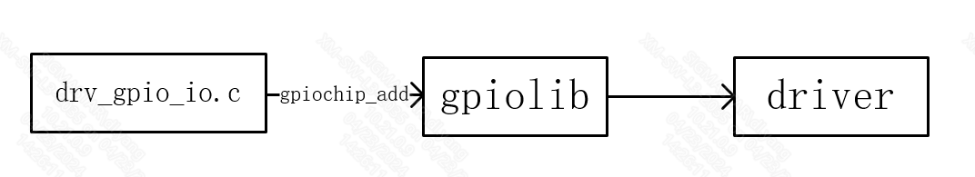
As illustrated in the GPIO framework above, the layer in the middle is gpiolib, for managing the GPIOs in the system. The gpiolib is a collection of the general GPIO operations. Depending on the characteristics of the GPIO, the gpiolib interfaces to a corresponding uniform software interface provided by other drivers for operating the GPIO. On the downward side, the gpiolib provides a set of frameworks to operate different chips. For different chips, you need only to implement drv_gpio_io.c and then use the registration function provided by gpiolib to mount it to the gpiolib.
2. Keyword
2.1. GPIO Index
To use the HW checklist, find the GPIO Index corresponding to the pad name of the GPIO in the schematics. The GPIO Index serves as the input parameter for software to operate the associated GPIO function.
For example, if PAD_KEY1 is the GPIO intended to be used, you should look up Table 1 to find the GPIO Index corresponding to this pad, which is 12 in this case.
Table 1: Mapping between GPIO Index and PAD
| Pad Name | GPIO Index | Pad Name | GPIO Index | Pad Name | GPIO Index |
|---|---|---|---|---|---|
| PAD_UART0_TX | 0 | PAD_PWM_OUT00 | 1 | PAD_PWM_OUT01 | 2 |
| PAD_SPI_CK | 3 | PAD_SPI_HLD | 4 | PAD_SPI_CZ | 5 |
| PAD_SPI_WPZ | 6 | PAD_SPI_DI | 7 | PAD_SPI_DO | 8 |
| PAD_GPIOE_00 | 9 | PAD_GPIOE_01 | 10 | PAD_GPIOE_02 | 11 |
| PAD_GPIOE_03 | 12 | PAD_GPIOE_04 | 13 | PAD_GPIOE_05 | 14 |
| PAD_GPIOE_06 | 15 | PAD_GPIOE_07 | 16 | PAD_GPIOE_08 | 17 |
| PAD_GPIOE_09 | 18 | PAD_GPIOE_10 | 19 | PAD_GPIOE_11 | 20 |
| PAD_GPIOE_12 | 21 | PAD_GPIOE_13 | 22 | PAD_GPIOE_14 | 23 |
| PAD_GPIOE_15 | 24 | PAD_GPIOE_16 | 25 | PAD_GPIOE_17 | 26 |
| PAD_GPIOE_18 | 27 | PAD_GPIOE_19 | 28 | PAD_GPIOE_20 | 29 |
| PAD_GPIOE_21 | 30 | PAD_GPIOE_22 | 31 | PAD_GPIOE_23 | 32 |
| PAD_GPIOE_24 | 33 | PAD_GPIOE_25 | 34 | PAD_GPIOE_26 | 35 |
| PAD_GPIOE_27 | 36 | PAD_GPIOE_28 | 37 | PAD_GPIOA_00 | 38 |
| PAD_GPIOA_01 | 39 | PAD_GPIOA_02 | 40 | PAD_GPIOA_03 | 41 |
| PAD_GPIOA_04 | 42 | PAD_GPIOA_05 | 43 | PAD_GPIOA_06 | 44 |
| PAD_GPIOA_07 | 45 | PAD_GPIOA_08 | 46 | PAD_GPIOA_09 | 47 |
| PAD_GPIOA_10 | 48 | PAD_GPIOA_11 | 49 | PAD_EMMC_RST | 50 |
| PAD_EMMC_CLK | 51 | PAD_EMMC_CMD | 52 | PAD_EMMC_DS | 53 |
| PAD_EMMC_D3 | 54 | PAD_EMMC_D4 | 55 | PAD_EMMC_D0 | 56 |
| PAD_EMMC_D5 | 57 | PAD_EMMC_D1 | 58 | PAD_EMMC_D6 | 59 |
| PAD_EMMC_D2 | 60 | PAD_EMMC_D7 | 61 | PAD_GPIOA_12 | 62 |
| PAD_GPIOA_13 | 63 | PAD_GPIOA_14 | 64 | PAD_GPIOA_15 | 65 |
| PAD_GPIOA_16 | 66 | PAD_GPIOA_17 | 67 | PAD_GPIOA_18 | 68 |
| PAD_GPIOA_19 | 69 | PAD_GPIOB_00 | 70 | PAD_GPIOB_01 | 71 |
| PAD_GPIOB_02 | 72 | PAD_GPIOB_03 | 73 | PAD_GPIOB_04 | 74 |
| PAD_GPIOB_05 | 75 | PAD_GPIOB_06 | 76 | PAD_GPIOB_07 | 77 |
| PAD_GPIOB_08 | 78 | PAD_OUTP_RX0_CH0 | 79 | PAD_OUTN_RX0_CH0 | 80 |
| PAD_OUTP_RX0_CH1 | 81 | PAD_OUTN_RX0_CH1 | 82 | PAD_OUTP_RX0_CH2 | 83 |
| PAD_OUTN_RX0_CH2 | 84 | PAD_OUTP_RX0_CH3 | 85 | PAD_OUTN_RX0_CH3 | 86 |
| PAD_GPIOC_00 | 87 | PAD_GPIOC_01 | 88 | PAD_GPIOC_02 | 89 |
| PAD_GPIOC_03 | 90 | PAD_GPIOC_04 | 91 | PAD_GPIOC_05 | 92 |
| PAD_GPIOC_06 | 93 | PAD_GPIOC_07 | 94 | PAD_GPIOC_08 | 95 |
| PAD_OUTP_CH0 | 96 | PAD_OUTN_CH0 | 97 | PAD_OUTP_CH1 | 98 |
| PAD_OUTN_CH1 | 99 | PAD_OUTP_CH2 | 100 | PAD_OUTN_CH2 | 101 |
| PAD_OUTP_CH3 | 102 | PAD_OUTN_CH3 | 103 | PAD_OUTP_CH4 | 104 |
| PAD_OUTN_CH4 | 105 | PAD_SAR_ADC0_00 | 106 | PAD_SAR_ADC0_01 | 107 |
| PAD_SAR_ADC0_02 | 108 | PAD_SAR_ADC0_03 | 109 | PAD_SAR_ADC0_04 | 110 |
| PAD_SAR_ADC0_05 | 111 | PAD_SAR_ADC0_06 | 112 | PAD_SAR_ADC0_07 | 113 |
| PAD_SAR_ADC0_08 | 114 | PAD_SAR_ADC0_09 | 115 | PAD_SAR_ADC0_10 | 116 |
| PAD_SAR_ADC0_11 | 117 | PAD_SAR_ADC0_12 | 118 | PAD_SAR_ADC0_13 | 119 |
| PAD_SAR_ADC0_14 | 120 | PAD_PWM_ADC01 | 121 | PAD_PWM_ADC00 | 122 |
| PAD_GPIOD_01 | 123 | PAD_GPIOD_02 | 124 | PAD_GPIOD_03 | 125 |
| PAD_GPIOD_00 | 126 | PAD_UART0_RX | 127 | PAD_PM_GPIO4 | 128 |
| PAD_PM_GPIO5 | 129 | PAD_PM_PWM1_OUT | 130 | PAD_PM_I2C_SDA | 131 |
| PAD_PM_PWM0_OUT | 132 | PAD_PM_I2C_SCL | 133 | PAD_PM_GPIO1 | 134 |
| PAD_PM_GPIO3 | 135 | PAD_PM_UART1_TX | 136 | PAD_PM_GPIO2 | 137 |
| PAD_PM_GPIO7 | 138 | PAD_PM_GPIO6 | 139 | PAD_PM_UART1_RX | 140 |
| PAD_PM_ADC00_IN | 141 | PAD_PM_GPIO0 | 142 | PAD_PM_SAR_GPIO0 | 143 |
| PAD_PM_SAR_GPIO1 | 144 | PAD_PM_SAR_GPIO2 | 145 | PAD_PM_SAR_GPIO3 | 146 |
| PAD_PM_SAR_GPIO4 | 147 |
3. Function Description
- There are 148 GPIO pins with numbers 0-147, all of which can be configured as GPIO Mode
- Support configuring the up and down states of gpio pins
- Support configuring the driver capability of gpio pins
4. Hardware Connection
Connect the corresponding gpio pin to the hardware.
5. Uboot Usage
5.1. Uboot Config
[*] SigmaStar drivers  --->

    [*]   SigmaStar GPIO
    [*]   SigmaStar padmux
5.2. Related Code Path
drivers/sstar/gpio/drv_gpio.c
drivers/sstar/gpio/drv_gpio.h
drivers/sstar/gpio/pcupid/hal_gpio.c
drivers/sstar/gpio/pcupid/hal_gpio.h
drivers/sstar/gpio/pcupid/hal_pinmux.c
drivers/sstar/gpio/pcupid/hal_pinmux.h
drivers/sstar/include/pcupid/gpio.h
drivers/sstar/include/pcupidpadmux.h
5.3. DTS Parameter Configuration
gpio: gpio {
    compatible = "sstar,gpio";
    status = "okay";
};
| Attribute | Description | Note |
|---|---|---|
| compatible | Used to match the driver for driver registration | Modification not allowed |
| status | Driver switch | okay/disabled; can be modified where necessary |
5.4. Uboot Command Parameter
<input|set|clear|toggle> <pin> → input/set/clear/toggle the specified pin
gpio status [-a] [<bank> | <pin>] → show [all / claimed] GPIOs
| Command | Parameter | Description |
|---|---|---|
| input | pin | Set the pin with the specified pin number as GPIO input mode |
| set | pin | Set the pin with the specified pin number as GPIO output high mode |
| clear | pin | Set the pin with the specified pin number as GPIO output low mode |
| toggle | pin | Toggle the level of the pin with the specified pin number |
| status | pin | Check the status of the pin with the specified pin number |
5.5. Uboot Command Usage Example
gpio input <gpio#> → gpio input 69 // gpio69 set as input
gpio set <gpio#> → gpio set 10 // gpio10 set as output high
gpio clear <gpio#> → gpio clear 49 // gpio49 set as output low
gpio toggle <gpio#> → gpio toggle 49 // gpio49 level toggle
gpio status <gpio#> → gpio status 20 // gpio20 status
5.6. Pin initial state setting
5.6.1. Uboot Config
When compiling Uboot: make menuconfig
[*] SigmaStar drivers  --->

    [*]   SigmaStar PAD_INIT
5.6.2. Function usage instructions
The initial state of the PAD includes input/output state, level state, internal pull-up state, and pin drive capability level. Therefore, when setting the initial state of the PAD, the above four states are mainly configured. The specific configuration format in xxx-padmux.dtsi is as follows:
/*
    * Format:
    * <Pad_Index   Direction       Level_State        Pull_State          Driving_Level>
    */
1. <PAD_OUTP_RX0_CH0 GPIO_DIR_IN    GPIO_LEVEL_NA     PAD_PULL_UP         PAD_DRV_1>,
2. <PAD_PM_I2C_SDA   GPIO_DIR_OUT   GPIO_LEVEL_HIGH   PAD_PULL_DOWN       PAD_DRV_1>,
3. <PAD_GPIOC_00     GPIO_DIR_NA    GPIO_LEVEL_NA     PAD_HIZ             PAD_DRV_3>,
4. <GPIO_NR     GPIO_DIR_NA     GPIO_LEVEL_NA      PAD_PULL_DEFAULT    PAD_DRV_DEFAULT>;
As shown above:
-
Pad_Index: Indicates the PAD number, refer to Table 1-1: GPIO NUM and PAD correspondence table.
-
Direction: Indicates the input/output mode of the Pad, which can be configured as: GPIO_DIR_IN, GPIO_DIR_OUT, GPIO_DIR_NA.
GPIO_DIR_IN means setting as input, and GPIO_DIR_OUT means setting as output. If you only need to set the internal pull-up state and driving capability level of the PAD, and do not need to set the PAD to GPIO mode, you can pass GPIO_DIR_NA in the Direction position. When the Pad is set to input/output mode, you need to set this Pad to GPIO mode, so you need to add the GPIO mode setting to the padmux configuration position
1.    <PAD_OUTP_RX0_CH0      PINMUX_FOR_GPIO_MODE      MDRV_PUSE_GPIO_OUTP_RX0_CH0>,
2.    <PAD_PM_I2C_SDA        PINMUX_FOR_GPIO_MODE      MDRV_PUSE_GPIO_PM_I2C_SDA>,
3.    <PAD_GPIOC_00          PINMUX_FOR_GPIO_MODE      MDRV_PUSE_GPIO_GPIOC_00>,
-
Level_State: Indicates the level high and low state, which can be configured as: GPIO_LEVEL_HIGH, GPIO_LEVEL_LOW, GPIO_LEVEL_NA.
GPIO_LEVEL_HIGH indicates high level, GPIO_LEVEL_LOW indicates low level, and GPIO_LEVEL_NA indicates that the initial level does not need to be configured, and the default level can be used.
-
Pull_State: Indicates the internal pull-up and pull-down state, which can be configured as: PAD_PULL_UP, PAD_PULL_DOWN, PAD_HIZ, PAD_PULL_DEFAULT.
PAD_PULL_UP indicates internal pull-up, PAD_PULL_DOWN indicates internal pull-down, and PAD_HIZ indicates floating. When you do not need to set the internal pull-up state, you can select PAD_PULL_DEFAULT to set it to the default state.
-
Driving_Level: Indicates the driving capability level, which can be configured as PAD_DRV_0, PAD_DRV_1, PAD_DRV_2... When you do not need to set the driving capability level, you can also select PAD_DRV_DEFAULT, that is, use the current driving capability level without configuration.
Name Config Direction GPIO_DIR_IN, GPIO_DIR_OUT, GPIO_DIR_NA Level_State GPIO_LEVEL_HIGH, GPIO_LEVEL_LOW, GPIO_LEVEL_NA Pull_State PAD_PULL_UP, PAD_PULL_DOWN, PAD_HIZ, PAD_PULL_DEFAULT Driving_Level PAD_DRV_0, PAD_DRV_1, PAD_DRV_2......PAD_DRV_DEFAULT
6. Kernel Usage
6.1. Kernel Config
Device Drivers  --->

    [*] GPIO Support  --->
        [*]   /sys/class/gpio/... (sysfs interface)

    [*] SStar SoC platform drivers  --->
        [*]   GPIO driver
        [*]   PADMUX driver
6.2. Related Code Path
drivers/sstar/gpio/drv_gpio.c
drivers/sstar/gpio/drv_gpio_io.c
drivers/sstar/gpio/pcupid/hal_gpio.c
drivers/sstar/gpio/pcupid/hal_gpio.h
drivers/sstar/gpio/pcupid/hal_pinmux.c
drivers/sstar/gpio/pcupid/hal_pinmux.h
drivers/sstar/gpio/os/gpio_os.h
drivers/sstar/gpio/ut/gpio_irq_test.c
drivers/sstar/include/pcupid/gpio.h
drivers/sstar/include/pcupid/padmux.h
6.3. DTS Parameter Configuration
gpio: gpio {
    compatible = "sstar,gpio";
    #gpio-cells = <2>;
    status = "okay";
};
| Attribute | Description | Note |
|---|---|---|
| compatible | Used to match the driver for driver registration | Modification not allowed |
| #gpio-cells | Used to declare the number of device node GPIO cells | If set to 2, the first cell represents the GPIO number and the second cell represents the effective level of the GPIO |
| status | Driver switch | ok/disabled; can be modified where necessary |
6.4. Module Usage Introduction
6.4.1. The export/unexport File Interface
The user space can operate the GPIO through sysfs interface.
The source code corresponding to /sys/class/gpio is located at driver/gpio/gpiolib-sysfs.c.
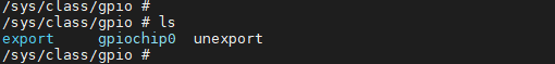
There are three files under the /sys/class/gpio directory, i.e. export/unexport, gpioN and gpio_chipN, as listed in the table below:
| Filename | Access Permission | Value | Description |
|---|---|---|---|
| export | wo | GPIO Index | Request control of a GPIO in user space |
| unexport | wo | GPIO Index | Remove control of a GPIO in user space |
| gpioN | ro | Information on a specific GPIO including direction, value, etc. | |
| gpio_chipN | ro | The GPIO controller |
-
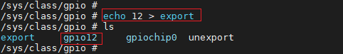
The /sys/class/gpio/export file is write-only and non-readable. The user program may write a specific GPIO index to kernel to request exportation of access right of a certain GPIO to user space (sysfs), provided that no application for exportation of access right against this GPIO interface is under processing by the kernel. Take GPIO index 12 as an example. You should enter the command:
# echo 12 > export
By this command, a node gpio12 will be created for the GPIO with Index 12, and a gpio12 directory will be created under /sys/class/gpio, as shown below:
-
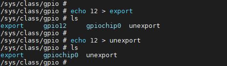
The /sys/class/gpio/unexport file is likewise write-only and non-readable. Contrary to the export function, the unexport command allows you to remove the user space (sysfs) interface by writing the GPIO index. To remove gpio12 file directory, for example, enter the following command:
# echo 12 > unexport
By this command, the gpio12 node will be removed, as illustrated below:
6.4.2. /sys/class/gpio/gpioN
/sys/class/gpio/gpioN refers to a specific GPIO port, wherein the following attribute files are included:
| Filename | Access Permission | Value | Description |
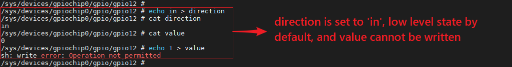
| direction | rw | in | Input mode, value is non-writable |
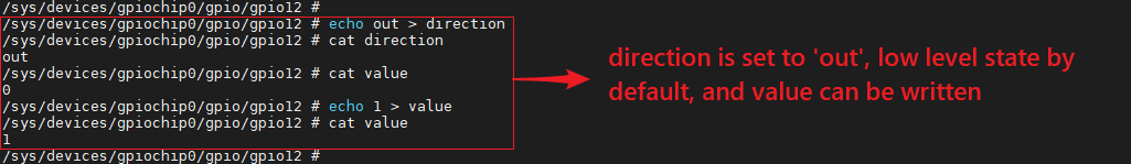
| out | Output mode, value is writable | ||
| high | Output state, high level by default, value is writable | ||
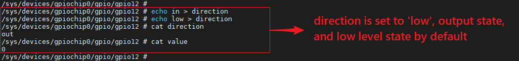
| low | Output state, low level by default, value is writable | ||
| value | rw | 1 | High level state |
| 0 | Low level state | ||
| edge | rw | none | Disable gpio interrupt |
| rising | Enable gpio interrupt, and set gpio as rising edge trigger | ||
| falling | Enable gpio interrupt, and set gpio as falling edge trigger | ||
| both | Enable gpio interrupt, and set gpio as both edge trigger |
direction, which indicates the direction of the GPIO port, that is, whether the read result is in or out. The read command is:
# cat direciton
value, which represents the level of the GPIO pin. 0 means low level, and 1 high level. The read command is:
# cat value
You can do write operation against the direction, using the command below:
# echo in > direction
# echo out > direction
If the direction is configured as out, the level will be low by default and the value will be writable by the following command:
# echo 1 > value

# echo 0 > value
When writing low or high to the direction, you can set the GPIO as output and configure the output level at the same time. The command to this effect is:
# echo high > direction
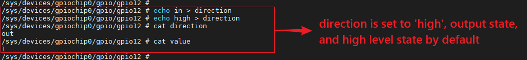
# echo low > direction
Of course, this attribute will not exist if it is not supported by the kernel or not allowed by the kernel code. For example, if the kernel calls gpio_export(N,0), it means that the kernel does not want to modify the direction attribute of the GPIO port.
edge, which means whether to enable gpio interrupt, and set trigger mode, supporting rising edge trigger, falling edge trigger and both edge trigger:
# cat edge
The write operation command to edge is:
# echo none > edge
# echo rising > edge
# echo falling > edge
# echo both > edge
If you need to enable a pin's interrupt, please set the pin as input status and set the trigger mode, then the poll(2) function can be called to monitor the interrupt, and the poll(2) function will return once the interrupt is triggered.
6.4.3. /sys/class/sstar/msys
The original LINUX GPIO framework currently does not support GPIO pull-up/pull-down and driving strength configuration. So, based on the standard LINUX GPIO framework, we have added an additional file interface for adjusting the pull-up/pull-down and driving strength of the GPIO. To support this function, open the CONFIG_MSYS_GPIO configuration in menuconfig: Device Drivers -> SStar SoC platform drivers -> msys api ->support GPIO pull and driving modify
The source code corresponding to /sys/class/sstar/msys is located at driver/sstar/msys/ms_msys.c.
Be sure to set the GPIO as input state before setting the pull-up/pull-down configuration, because the pull-up/pull-down resistor value cannot be measured when the GPIO is in output state:

After setting the pin as input state, enter the file directory sys/class/sstar/msys:
-
gpio_pull, which can be configured as up or down
Filename Access Permission Value Description gpio_pull rw up Pull-up Mode down Pull-down Mode To check whether the pull state of the GPIO is currently pull-up, pull-down or pull-off:
1. # echo 50 > gpio_pull
2. # cat gpio_pull
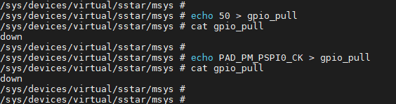
If the input GPIO Index or GPIO Name is illegal, an error will be returned:
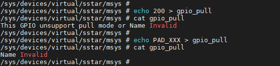
The command to set the GPIO pull state is:
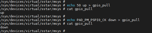
1. # echo 50 up > gpio_pull
2. # echo 50 down > gpio_pull
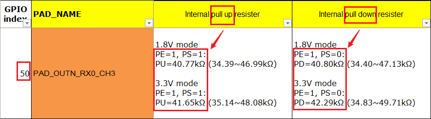
You can check the GPIO pull state after completing the setting, using the command below, wherein 50 represents the GPIO Index and PAD_OUTN_RX0_CH3 represents the GPIO Name.
1. # cat gpio_pull
If the input GPIO Index or GPIO Name is illegal, an error will be returned:
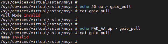
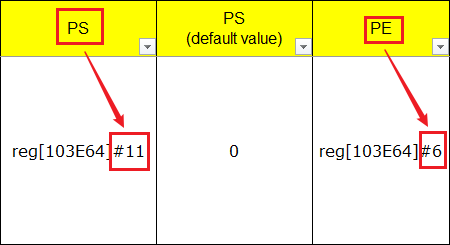
To check whether a specific bit has been correctly written, look up the HW checklist to find the corresponding PAD (for example GPIO INDEX: 50 below). When pulled up, the PE bit will be 1 and the PS bit will be 0; when pulled down, the PE bit will be 1 and the PS bit will be 0. The command to this effect is:
1. # riu_r 0x103e 0x34
To check Bit 6 and Bit 11 of riu_r return value:
-
gpio_drive, which can set the level of the driving strength
Filename Access Permission Value Description gpio_drive rw 0~8 Set the level of the GPIO driving strength The level of GPIO driving strength can be checked using the HW checklist.
To check the command bit of the initial driving strength of the GPIO (you can directly use the Pad Name of GPIO43, PAD_OUTP_RX0_CH0 too):
1. # echo 43 > gpio_drive
2. # cat gpio_drive
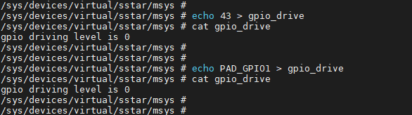
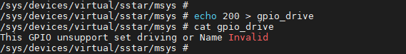
If the input GPIO Index or GPIO Name is illegal, an error will be returned:
Before configuring the driving strength, set the GPIO in high-level output state for purpose of measurement. The command to this effect is:
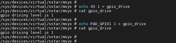
1. # echo 43 1 > gpio_drive
wherein, 43 refers to the GPIO Index and 1 refers to the level of the driving strength, which corresponds to 4mA.
After setting the driving strength, check the state of the gpio_driver using the command set forth below. As illustrated, the driving strength of the pin with GPIO Index 43 has been set to 4mA successfully.
1. # cat gpio_drive
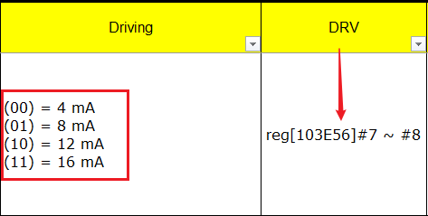
To check whether a specific bit has been corrected written, look up the HW checklist to find the corresponding PAD (for example GPIO INDEX: 50 below). When the level of the driving strength is 1, [103E56]#7 ~ #8 will be 01. The command to this effect is:
1. # riu_r 0x103e 0x2B
To check Bit 7 and Bit 8 of riu_r return value:
6.4.4. Usage of Multiplexing Function
When you want to use the multiplexing function of GPIO, you need first to obtain the name of the pin to be operated and the Tmux Mode to be multiplexed, and then configure them in xxx-padmux.dtsi:
<PAD_EMMC_RST            PINMUX_FOR_EMMC8B_BOOT_MODE_1    MDRV_PUSE_EMMC_RST>,
<PAD_EMMC_CLK            PINMUX_FOR_EMMC8B_BOOT_MODE_1    MDRV_PUSE_EMMC_CLK>,
<PAD_EMMC_CMD            PINMUX_FOR_EMMC8B_BOOT_MODE_1    MDRV_PUSE_EMMC_CMD>,
<PAD_EMMC_D0             PINMUX_FOR_EMMC8B_BOOT_MODE_1    MDRV_PUSE_EMMC_D0>,
<PAD_EMMC_D1             PINMUX_FOR_EMMC8B_BOOT_MODE_1    MDRV_PUSE_EMMC_D1>,
<PAD_EMMC_D2             PINMUX_FOR_EMMC8B_BOOT_MODE_1    MDRV_PUSE_EMMC_D2>,
<PAD_EMMC_D3             PINMUX_FOR_EMMC8B_BOOT_MODE_1    MDRV_PUSE_EMMC_D3>,
<PAD_EMMC_D4             PINMUX_FOR_EMMC8B_BOOT_MODE_1    MDRV_PUSE_EMMC_D4>,
<PAD_EMMC_D5             PINMUX_FOR_EMMC8B_BOOT_MODE_1    MDRV_PUSE_EMMC_D5>,
<PAD_EMMC_D6             PINMUX_FOR_EMMC8B_BOOT_MODE_1    MDRV_PUSE_EMMC_D6>,
<PAD_EMMC_D7             PINMUX_FOR_EMMC8B_BOOT_MODE_1    MDRV_PUSE_EMMC_D7>,
<PAD_EMMC_DS             PINMUX_FOR_EMMC8B_BOOT_MODE_1    MDRV_PUSE_EMMC_DS>,
As shown above, the first column and the second column represent Pad Name and Tmux Mode respectively, wherein MDRV_PUSE_XXX can be understood as the name of the current configuration of this group.
Note that there are some things to pay attention to when configuring the multiplexing function:
-
Each pad can only be configured with one mode; it is not allowed to configure one pad with multiple modes at the same time.
-
Each pulse can only correspond to one set of configuration; otherwise, conflicts will occur.
-
The Pad and Mode configured must match.
-
It is not allowed to perform multiplexing operations directly in the driver; the multiplexing configurations should be incorporated into xxx_padmux.dtsi collectively (except those requiring dynamical adjustment of the multiplexing configuration), to facilitate management and reduce configuration conflicts.
6.4.5. Pin initial state setting
When compiling the kernel: make menuconfig
Device Drivers-->
    [*] SStar SoC platform drivers-->
        [*] PAD_INIT driver
For details, please refer to this article section: Function usage instructions
6.5. Sample Code
6.5.1 User space interruption
For user space code to enable GPIO interrupt, please refer to sstargpio_poll.c.
1.    #include <stdio.h>
2.    #include <stdlib.h>
3.    #include <unistd.h>
4.    #include <fcntl.h>
5.    #include <sys/poll.h>
6.
7.    int main(int argc, char *argv[])
8.    {
9.        char buff[1024];
10.        int gpio_id;
12.        struct pollfd fds[1];
13.        int gpio_fd = open("/sys/class/gpio/gpio135/value", O_RDONLY);
14.        if (gpio_fd == -1)
15.            {printf("gpio open\n");}
16.        else
17.            {printf("/sys/class/gpio/gpio135/value\n");}
18.        fds[0].fd = gpio_fd;
19.        fds[0].events = POLLPRI;
20.        int ret = read(gpio_fd, buff, 10);
21.        if (ret == -1)
22.            printf("read fail\n");
23.        else
24.            printf("read\n");
25.        while (1)
26.        {
27.            printf("revents is %d\n", fds[0].revents);
28.            ret = poll(fds, 1, -1);
29.            if (ret == -1)
30.                printf("poll\n");
31.
32.            if (fds[0].revents & POLLPRI)
33.            {
34.                ret = lseek(gpio_fd, 0, SEEK_SET);
35.                if (ret == -1)
36.                    printf("lseek\n");
37.                ret = read(gpio_fd, buff, 10);
38.                if (ret == -1)
39.                    printf("read\n");
40.                printf("get interrupt\n");
41.            }
42.        }
43.    }
6.5.2 API USE Reference
#include <drv_gpio.h>

int main()
{
    u8 index = 0;
    gpio_request(index,"test");
    gpio_direction_input(index);

    //do your operation
    gpio_set_value(index,1);

    //.....

    gpio_free(index);
}
7. API Reference
This module provides the following interfaces:
| API Name | Function |
|---|---|
| gpio_request | Create a GPIO port. |
| gpio_free | Free a GPIO port. |
| gpio_direction_input | Set a GPIO as an input port. |
| gpio_direction_output | Set a GPIO as an output port. |
| gpio_get_value | Get the input level of an input pin. |
| gpio_set_value | Set the level of an output pin. |
| sstar_gpio_pad_set | Set a pin as GPIO mode. |
| sstar_gpio_pad_clr | Clear a pin as GPIO mode. |
| sstar_gpio_pad_val_set | Set the TMUX mode of a pin. |
| sstar_gpio_pad_val_get | Configured PadMode of a certain Pad. |
| sstar_gpio_vol_val_set | Set the voltage mode of a pin. |
| sstar_gpio_pad_in_out | Get the state of a pin. |
| sstar_gpio_pull_up | Enable the pull-up function of a specific GPIO. |
| sstar_gpio_pull_down | Enable the pull-down function of a specific GPIO. |
| sstar_gpio_pull_off | Disable the pull-up/pull-down and switch to the floating state. |
| sstar_gpio_pull_status | Get the pull-up/pull-down state of a specific GPIO. |
| sstar_gpio_drv_set | Set the driving strength of a specific GPIO. |
| sstar_gpio_drv_get | Get the level of driving strength of a specific GPIO. |
| sstar_gpio_to_irq | Get the IRQ index of a specific GPIO. |
| sstar_gpio_name_to_num | Get the GPIO Index based on the GPIO Name. |
| sstar_gpio_padmode_to_padindex | Query all GPIO pins that can use a specific PadMode. |
| mdrv_padmux_getpad | Use Puse as the search condition to obtain the Pad configured. |
| mdrv_padmux_getmode | Use Puse as the search condition to obtain the Tmux Mode configured. |
| mdrv_padmux_getpuse | Puse can be obtained according to these three parameters. |
7.1. gpio_request
-
Purpose
Create a GPIO port.
-
Syntax
int gpio_request(unsigned gpio, const char *label)
-
Parameter
Parameter Name Description gpio GPIO Index label GPIO name -
Return Value
Return Value Description 0 Success other Fail
7.2. gpio_free
-
Purpose
Free a GPIO port.
-
Syntax
void gpio_free(unsigned gpio)
-
Parameter
Parameter Name Description gpio GPIO Index -
Return Value
None void Description Return Value
7.3. gpio_direction_input
-
Purpose
Set a GPIO as an input port.
-
Syntax
int gpio_direction_input(unsigned gpio);
-
Parameter
Parameter Name Description gpio GPIO Index -
Return Value
Return Value Description 0 Success other Fail
7.4. gpio_direction_output
-
Purpose
Set a GPIO as an output port.
-
Syntax
int gpio_direction_output(unsigned gpio, int value);
-
Parameter
Parameter Name Description gpio GPIO Index value Output value -
Return Value
Return Value Description 0 Success other Fail
7.5. gpio_get_value
-
Purpose
Get the input level of an input pin.
-
Syntax
int gpio_get_value(unsigned gpio);
-
Parameter
Parameter Name Description gpio GPIO Index -
Return Value
Return Value Description int Level value
7.6. gpio_set_value
-
Purpose
Set the level of an output pin.
-
Syntax
void gpio_set_value(unsigned gpio, int value);
-
Parameter
Parameter Name Description gpio GPIO Index value Output value -
Return Value
Return Value Description 0 Success other Fail
7.7. sstar_gpio_pad_set
-
Purpose
Set a pin as GPIO mode.
-
Syntax
void sstar_gpio_pad_set(U8 gpio_index);
-
Parameter
Parameter Name Description gpio_index GPIO Index -
Return Value
Return Value Description void None
7.8. sstar_gpio_pad_clr
-
Purpose
Clear the GPIO mode of a pin.
-
Syntax
void sstar_gpio_pad_clr(U8 gpio_index);
-
Parameter
Parameter Name Description gpio_index GPIO Index -
Return Value
Return Value Description void None
7.9. sstar_gpio_pad_val_set
-
Purpose
Set the TMUX mode of a pin.
-
Syntax
U8 sstar_gpio_pad_val_set(U8 gpio_index, U32 pad_mode);
-
Parameter
Parameter Name Description gpio_index GPIO Index pad_mode TMUX MODE -
Return Value
Return Value Description 1 Incorrect input parameter 0 Success
7.10. sstar_gpio_pad_val_get
-
Purpose
This API is used to get the currently configured PadMode of a certain Pad, provided that when configuring PadMode for this Pad, it is configured through the Padmux interface. Directly operating registers for configuration will not make this API effective.
-
Syntax
U8 sstar_gpio_pad_val_get(U8 gpio_index, U32* pad_mode);
-
Parameter
Parameter Name Description gpio_index Group Index pad_mode The TMUX MODE gotten -
Return Value
Return Value Description 1 Incorrect output parameter 0 Success
7.11. sstar_gpio_vol_val_set
-
Purpose
Set the voltage mode of a pin. Note that this API is only supported by Muffin.
-
Syntax
void sstar_gpio_vol_val_set(U8 group, U32 mode);
-
Parameter
Parameter Name Description group Group num (11 Groups in total) mode Mode = 0: Voltage of the pin is 3.3V; Mode = 1: Voltage of the pin is 1.8V -
Return Value
Return Value Description void None
7.12. sstar_gpio_pad_in_out
-
Purpose
Get the state of a pin.
-
Syntax
U8 sstar_gpio_pad_in_out(U8 gpio_index, U8* pad_in_out);
-
Parameter
Parameter Name Description gpio_index GPIO Index pad_in_out 1 means the pin is in output state; 0 means the pin is in input state -
Return Value
Return Value Description 1 Incorrect input parameter 0 Success
7.13. sstar_gpio_pull_up
-
Purpose
Enable the pull-up function of a specific GPIO.
-
Syntax
U8 sstar_gpio_pull_up(U8 gpio_index);
-
Parameter
Parameter Name Description gpio_index GPIO Index -
Return Value
Return Value Description 0 Success other Pull-up function not supported by the pin or incorrect input parameter
7.14. sstar_gpio_pull_down
-
Purpose
Enable the pull-down function of a specific GPIO.
-
Syntax
U8 sstar_gpio_pull_down(U8 gpio_index);
-
Parameter
Parameter Name Description gpio_index GPIO Index -
Return Value
Return Value Description 0 Success other Pull-down function not supported by the pin or incorrect input parameter
7.15. sstar_gpio_pull_off
-
Purpose
Disable the pull-up/pull-down function of a specific GPIO and switch to the floating state.
-
Syntax
U8 sstar_gpio_pull_off(U8 gpio_index);
-
Parameter
Parameter Name Description gpio_index GPIO Index -
Return Value
Return Value Description 0 Success other Pull-up function not supported by the pin or incorrect input parameter
7.16. sstar_gpio_pull_status
-
Purpose
Get the pull-up/pull-down state of a specific GPIO.
-
Syntax
U8 sstar_gpio_pull_status(U8 gpio_index, U8* pull_status);
-
Parameter
Parameter Name Description gpio_index GPIO Index pull_status The pull-up/pull-down state gotten -
Return Value
Return Value Description 0 Success 1 Pull-up function not supported by the pin or incorrect input parameter
7.17. sstar_gpio_drv_set
-
Purpose
Set the driving strength of a specific GPIO.
-
Syntax
U8 sstar_gpio_drv_set(U8 gpio_index, U8 level);
-
Parameter
Parameter Name Description gpio_index GPIO Index level Level of the driving strength -
Return Value
Return Value Description 0 Success other Driving strength configuration not supported by the pin or incorrect input parameter
7.18. sstar_gpio_drv_get
-
Purpose
Get the level of driving strength of a specific GPIO.
-
Syntax
U8 sstar_gpio_drv_get(U8 gpio_index, U8* level);
-
Parameter
Parameter Name Description gpio_index GPIO Index level The level of driving strength gotten -
Return Value
Return Value Description 0 Success 1 Driving strength configuration not supported by the pin or incorrect input parameter
7.19. sstar_gpio_to_irq
-
Purpose
Get the IRQ index of a specific GPIO.
-
Syntax
int sstar_gpio_to_irq(U8 gpio_index);
-
Parameter
Parameter Name Description gpio_index GPIO Index -
Return Value
Return Value Description virq The IRQ index returned Negative number or 0 Fail
7.20. sstar_gpio_name_to_num
-
Purpose
Get the GPIO Index based on the GPIO Name.
-
Syntax
U8 sstar_gpio_name_to_num(U8* p_name, U8* gpio_index);
-
Parameter
Parameter Name Description p_name GPIO Name gpio_index The GPIO Index gotten -
Return Value
Return Value Description 1 Incorrect input parameter 0 Success
7.21. sstar_gpio_padmode_to_padindex
-
Purpose
Query all GPIO pins that can use a specific PadMode.
-
Syntax
U32* sstar_gpio_padmode_to_padindex(U32 mode);
-
Parameter
Parameter Name Description mode The PadMode to be queried -
Return Value
Return Value Description Array start address The array in which the GPIO Index is stored
7.22. mdrv_padmux_getpad
-
Purpose
Use Puse as the search condition to obtain the Pad configured in xxx-padmux.dtsi.
-
Syntax
int mdrv_padmux_getpad (int Puse);
-
Parameter
Parameter Name Description Puse Puse macro definition -
Return Value
Return Value Description PadId Pad macro definition has been successfully gotten from padmux.dtsi PAD_UNKNOWN The input Puse is incorrect or corresponding PadId is not found in padmux.dtsi
7.23. mdrv_padmux_getmode
-
Purpose
Use Puse as the search condition to obtain the Tmux Mode configured in xxx-padmux.dtsi.
-
Syntax
int mdrv_padmux_getmode (int Puse);
-
Parameter
Parameter Name Description Puse Puse macro definition -
Return Value
Return Value Description PadId Pad macro definition has been successfully gotten from padmux.dtsi PAD_UNKNOWN The input Puse is incorrect or corresponding PadId is not found in padmux.dtsi
7.24. mdrv_padmux_getpuse
-
Purpose
The macro definition of PUSE follows a set of rules:
-
The offset between different IPs is 0x10000
-
The offset between different Channels in the same IP is 0x100
-
The offset between different Puses in the same channel with the same IP is 0x1
As such, the macro definition of Puse can be obtained according to these three parameters.
-
-
Syntax
int mdrv_padmux_getpuse (int IP_Index, int Channel_Index, int Pad_Index);
-
Parameter
Parameter Name Description IP_Index The IP where the Puse is located, which can be found in mdrv_puse.h Channel_Index The Channel where the Puse is located, which can be found in mdrv_puse.h Pad_Index The Index of the Puse in channel, which can be found in mdrv_puse.h -
Return Value
Return Value Description Puse PadId has been successfully gotten from padmux.dtsi
8. FAQ
When there is an exception in operating gpio, you can refer to the following points for debugging.
| Questions | Resolution |
|---|---|
| Export cannot pull high or low | The voltmeter actually measures, write directly to the register |
| Padmode exception | Use the iocheck tool to check if the padmode setting is correct |
8.1. Export cannot pull high or low
Operate the register corresponding to the gpio pin to pull up and down, use a voltmeter to measure for any changes, and locate whether the cat value or set value is incorrect.
8.2. Padmode exception
In the kernel/stard/drivers/gpio/ut/io_check directory, simply make to generate the prog_iocheck tool, package it to the customer partition, and start using it.
The supported options are as follows:
| Option | Function |
|---|---|
| -s | set padmux mode |
| -g | get padmux mode |
| -i | Specify pin index |
| -m | Specify mode |
| -v | Verify Padmux mode conflicts |
Example: To query a certain gpio pin, its index is index
Query the current reuse status: ./prog_io_check -i index
Set as corresponding mode: ./prog_io_check -i index -m mode_index -s