RTC User Guide
REVISION HISTORY
| Revision No. | Description |
Date |
|---|---|---|
| 1.0 | 04/17/2025 |
1. Overview
Real Time Clock (hereinafter referred to as RTC) is mainly used for timing and alarm clock setting. Developed on the basis of standard LINUX framework, the RTC driver can utilize a uniform interface to operate the RTC. Moreover, additional functions related to PWC (Power Controller) have been added to the LINUX framework to meet more SigmaStar IP requirements.
The PWC (Power Controller) controls the high/low levels of PAD_RTC_IO4 and PAD_RTC_IO5 upon detecting a wake-up source trigger event. The PAD_RTC_IO4 and PAD_RTC_IO5 then control the external power chip, thereby assuming control over the power of the entire board.
2. KEYWORD DESCRIPTION
-
Alarm
RTC support destination installation one hard time, this RTC arrival check time, meeting RTC Alarm incident.
-
Offset
RTC support frequency shift function, ability to operate in forward/reverse direction every 32 to 1Hz time.
-
REG
Haa[b] format for textual REG transcription, display offset: 0xaa's BITb, REG uniformly exists bank: 0x34 above explanation.
3. Function description
-
RTC current use 32.768kHz frequency crystal, construction circumscribed 32K crystal. No external crystal oscillation time, RTC's internal crystal oscillation from CLK, it is easy to accept temperature, temperature is affected by external factors such as electricity, influence RTC's accuracy.
-
RTC's basic functions comprehensive support hardware time reading and setting, support hardware time reading and setting.
-
PWC support communication control PAD_RTC_IO4 and PAD_RTC_IO5 high and low power, and control mutual power source area, common wake source comprehensive: RTC Alarm, PAD_RTC_IO0, PAD_RTC_IO1, PAD_RTC_IO2, PAD_RTC_IO3.
-
Table of RTC/PWC support information for different chips
chipname RTC PWC ALARM IO0 IO1 IO2 IO3 iford Y Y Y Y Y / / ifado Y / Y / / / / pcupid Y Y Y / Y / Y ibopper Y / Y / / / / ifackel Y / Y / / / /
4. Hardware connection
4.1. PWC System Architecture

The PWC controls the high/low levels of PAD_RTC_IO4 and PAD_RTC_IO5 through a wake-up source trigger event. The PAD_RTC_IO4 and PAD_RTC_IO5 then control the external power chip, thereby assuming control over the power of the entire board.
The wake-up sources that the RTC can control include:
-
Wake-up by a combination of PAD_RTC_IO0 - PAD_RTC_IO3 keys/waveforms
-
RTC Alarm interrupt wake-up
-
sw ctrl (software control)
The system architecture is illustrated in the figure below:
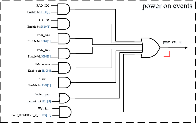
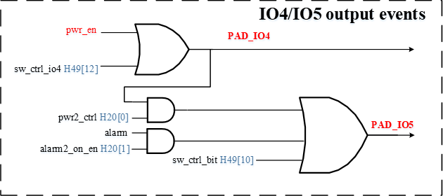
Note: The power_on_st in Figure 2-2 and the pwr_en in Figure 2-3 are hardware connected.
Combining Figure 2-2 and Figure 2-3, we can see that the event triggering of PAD_RTC_IO0 - PAD_RTC_IO3 and the event triggering of RTC Alarm can make the power_on state machine inside the rtc output a high level, and then go along the power_on state machine to pwr_en to pull up the level of PAD_RTC_IO4. At the same time, the triggering of the sw ctrl event (writing 1 to the sw_ctrl_bit register) can also control the level of PAD_RTC_IO4.
Moreover, as shown in Figure 2-3, the level of PAD_RTC_IO4, the event trigger of RTC Alarm and the trigger of sw ctrl event will affect the level of PAD_RTC_IO5. So these trigger events and the interaction between PAD_RTC_IO4 and PAD_RTC_IO5 can be flexibly used to realize power control. For details on the software configuration method, please refer to the Kernel Usage chapter below.
The current platform does not have PAD_RTC_IO0 and PAD_RTC_IO2. Please ignore the content related to PAD_RTC_IO0 and PAD_RTC_IO2.
4.2. PAD_RTC_IO0 Configuration
PAD_RTC_IO0 supports pull-down mode and high-impedance mode. The default setting is pull-down mode. For details on the software configuration method, please refer to the Kernel Usage chapter below.
4.3. PAD_RTC_IO1 Configuration
PAD_RTC_IO1 supports pull-down (PD) configuration only. Modification by software is not allowed. The internal block diagram is as follows:

4.4. PAD_RTC_IO2 Configuration
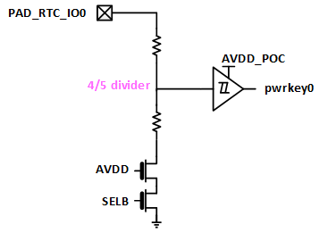
PAD_RTC_IO2 supports configuration of thresholds for internal high/low voltage comparator. Besides, PAD_RTC_IO2 can selectively connect to the embedded Schmitt trigger to enable the capture of different signals. The internal block diagram of PAD_RTC_IO2 is as follows:

The Schmitt trigger can implement the same logic by the comparator. Currently, the driver does not support the function of switching PAD_RTC_IO2 to Schmitt trigger. The types of configuration supported by PAD_RTC_IO2 include CMPHL (compare high and low), CMPH (compare low), CMPL (compare high)
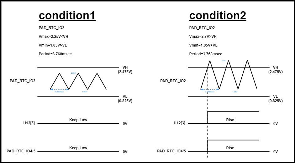
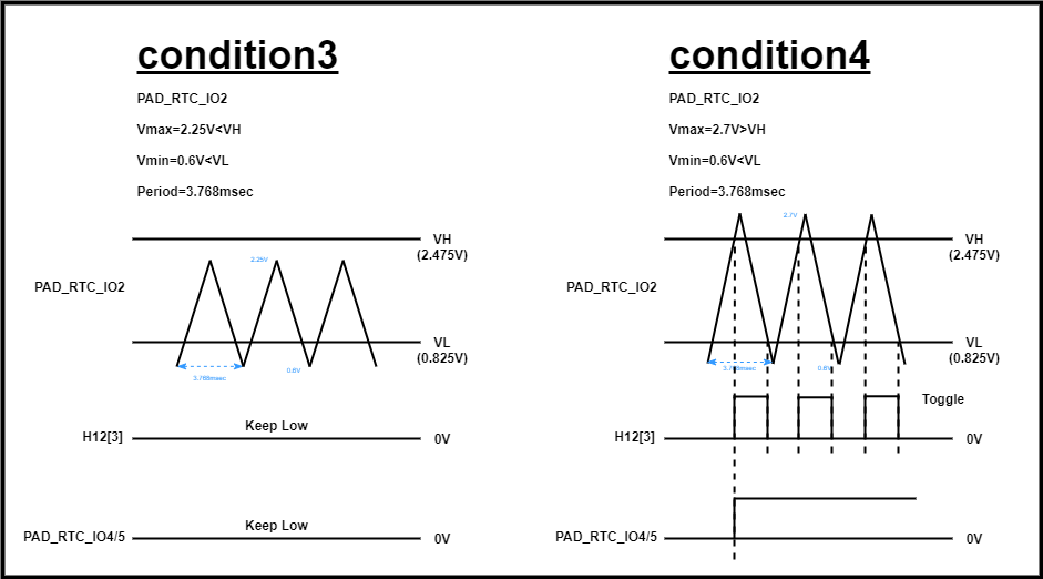
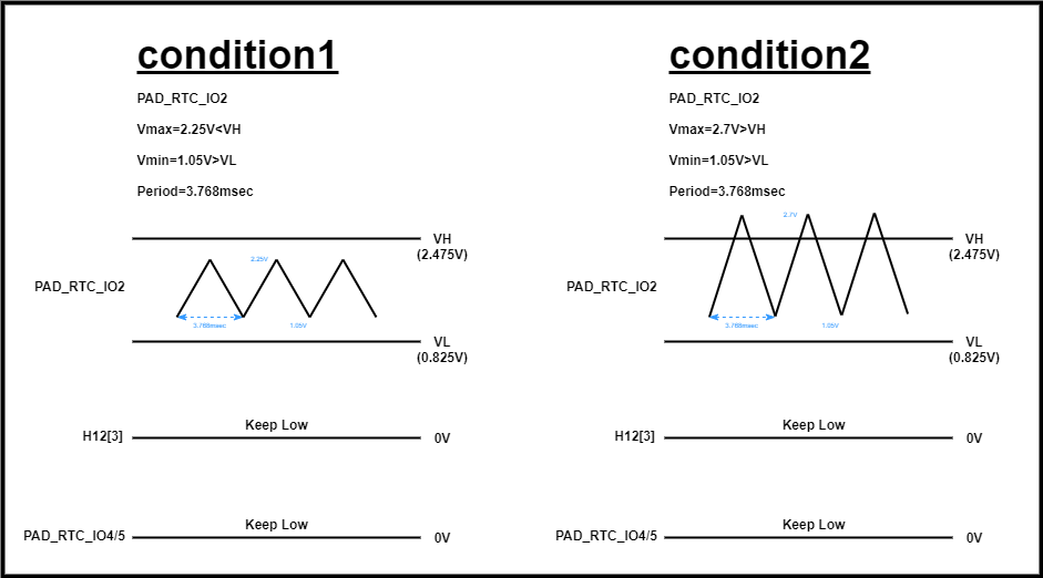
4.4.1. CMPHL
The relationship among PAD_RTC_IO2, Register Offset 0x12 and PAD_RTC_IO⅘ is as follows:
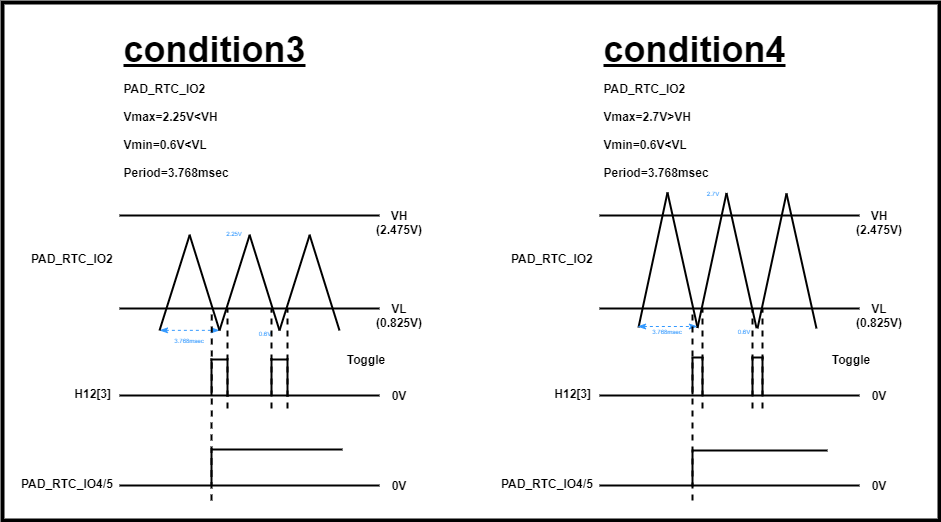
4.4.2. CMPL
The relationship among PAD_RTC_IO2, Register Offset 0x12 and PAD_RTC_IO⅘ is as follows:
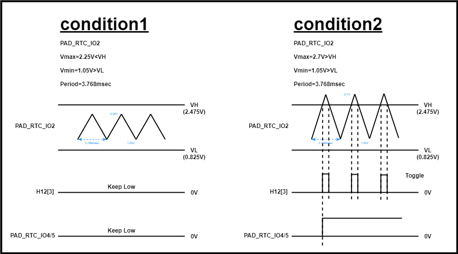
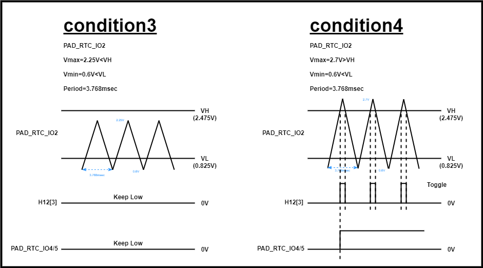
4.4.3. CMPH
The relationship among PAD_RTC_IO2, Register Offset 0x12 and PAD_RTC_IO⅘ is as follows:
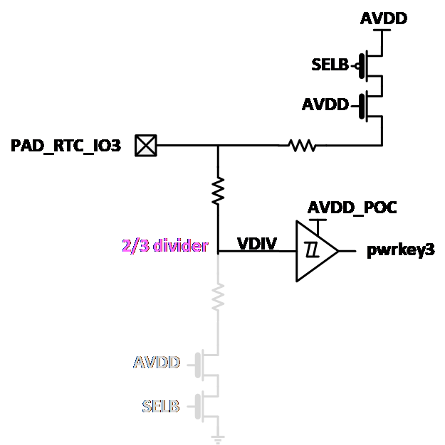
4.5. PAD_RTC_IO3 Configuration
PAD_RTC_IO3 supports pull-down mode and pull-up mode. The default setting is pull-down mode.

The internal block diagram of pull-up mode is as follows:
5. Uboot usage introduction
RTC has no driver under Uboot
6. Kernel Usage
6.1. Kernel Config
-
RTC related modules
-
interrupt
-
input
-
The configurations that need to be selected when compiling the kernel are as follows:
Device Drivers --->

    <*> Sstar RTC Driver --->

        [*]     Sstar RTC With PWC                           // Enable PWC function
                  Sstar PWC IO Mode (Interrupt Mode)  --->   // Switch RTC_IO's Interrupts mode and Polling mode
        [*]     Sstar RTC With Alarm                         // Enable RTC Alarm function
        [*]     Sstar RTC With Offset                        // Enable RTC time compensation function
6.2. DTS Configuration Parameter
        rtcpwc: rtcpwc {
            compatible = "sstar,rtcpwc";
            reg = <0x1F006800 0x200>;
            interrupts=<GIC_SPI INT_IRQ_FLAG_POC IRQ_TYPE_LEVEL_HIGH>;
            // io0-hiz;
            // io2-wos = <1>;           //0:CMPHL 1:CMPHL 2:CMPL 3:CMPH
            // io2-wos-v = <0x2 0x3>;   //<vl vh> 0<vl<8 0<vh<8
            // io3-pu;
            // offset-count = <100>;
            // offset-nagative;
            // iso-auto-regen;
            /*
             * io4 control source selection
             * io0/io1/io2/io3 ctrl bit0
             * alarm ctrl           bit1
             * sw ctrl              bit2
             * support the combination of above ways
             */
            io4-enable = <7>;
            /*
             * io5 control source selection
             * io4 ctrl    bit0
             * alarm ctrl  bit1
             * sw ctrl     bit2
             * support the combination of above ways
             */
            io5-enable = <7>;   // for demo board,use 3,default hight
            // io5-no-poweroff;    // io5 keep when excute 'poweroff'
            // auto-down-disable; // IO4/5 will not automatically pull down when PM power is off
            status = "ok";

#ifdef CONFIG_SSTAR_PWC_IO_POLLING
            poll-interval = <10>;
#endif /* CONFIG_SSTAR_PWC_IO_POLLING */
            io1 {
                num = <1>;
                keycode = <KEY_WAKEUP>;
#ifdef CONFIG_SSTAR_PWC_IO_POLLING
                debounce-interval = <10>;
#endif /* CONFIG_SSTAR_PWC_IO_POLLING */
#ifdef CONFIG_SSTAR_PWC_IO_INTERRUPT
                interrupt-parent = <&sstar_pm_gpi_intc>;
                interrupts = <INT_PM_GPI_FIQ_PAD_RTC_IO1>;
#endif /* CONFIG_SSTAR_PWC_IO_INTERRUPT */
            };
        };
| Attribute | Description | Note |
|---|---|---|
| compatible | Used to match the driver for driver registration | Modification not allowed |
| reg | Register mapped physical address | Modification not allowed |
| interrupts | Interrupt number and attributes | Modification not allowed |
| io0-hiz | Configure PAD_RTC_IO0 as High Z mode | Can be modified where necessary; pull-down mode will be used by default if this attribute is not configured. |
| io2-wos | Configure PAD_RTC_IO2 comparator type | 0: CMPHL, 1: CMPHL, 2: CMPL, 3: CMPH. See Hardware Introduction for details. |
| io2-wos-v | Configure PAD_RTC_IO2 comparator voltage | For details, please refer to Note 1. |
| io3-pu | Configure PAD_RTC_IO3 as Pull-up mode | Can be modified where necessary; pull-down mode will be used by default if this attribute is not configured. |
| offset-count | Configure the compensation value for frequency offset | For details, please refer to Note 2. |
| offset-nagative | Configure the frequency offset as pre-compensation | Can be modified where necessary; post-compensation will be used by default if this attribute is not configured. |
| iso-auto-regen | Always-on RTC register re-trigger mechanism: re-trigger when register setting has problems | No configuration required by default. When problems occur, the code will automatically turn it on, and turn it off after recovery |
| io4-enable | Used to configure the trigger mode of PAD_RTC_IO4 | For details, please refer to Note 3. |
| io5-enable | Used to configure the trigger mode of PAD_RTC_IO5 | For details, please refer to Note 3. |
| auto-down-disable | Disable the function of "IO⅘ automatically pulls down when pm domain is powered off" | Configure as needed, see Note 5 for detailed remarks |
| status | Driver switch | ok/disabled, can be modified where necessary |
| poll-interval | Interval of polling | Can be modified where necessary, in milliseconds |
| num | RTC_IO index | Configure as needed, see Note 4 for detailed remarks |
| keycode | Key value | Configure as needed, see Note 4 for detailed remarks |
| debounce-interval | Debounce of polling | Can be modified where necessary, in milliseconds |
| interrupt-parent | Interrupt parent of RTCIO | Modification not allowed |
| interrupts | Interrupt number | Modification not allowed |
Note 1: The first value in the io2-wos-v attribute represents VL, and the second value represents VH. The values allowed by VL and VH are given in the table below.
| Attribute Value | VL | VL Voltage | VH | VH Voltage |
|---|---|---|---|---|
| 0 | 1/16 AVDD | 0.206 | 15/16 AVDD | 3.094 |
| 1 | 2/16 AVDD | 0.413 | 14/16 AVDD | 2.888 |
| 2 | 3/16 AVDD | 0.619 | 13/16 AVDD | 2.681 |
| 3 | 4/16 AVDD | 0.825 | 12/16 AVDD | 2.475 |
| 4 | 5/16 AVDD | 1.031 | 11/16 AVDD | 2.269 |
| 5 | 6/16 AVDD | 1.238 | 10/16 AVDD | 2.063 |
| 6 | 7/16 AVDD | 1.444 | 9/16 AVDD | 1.856 |
| 7 | 8/16 AVDD | 1.650 | 8/16 AVDD | 1.650 |
The VL/VH voltage value in this table is the voltage value when AVDD is 3.3V.
The hardware default value is 3. If io2-wos attribute is defined and the io2-wos-v attribute is not defined in dtsi, then the value of io2-wos-v will be set to 0.
Note 2: The RTC counting function might have some frequency offset due to factors such as crystal oscillator tolerance, PCB tolerance, etc., which will further lead to offset in RTC timing. In order to compensate for offset caused by such manufacturing processes, the RTC features a frequency offset function. The frequency offset compensation error can be debugged and calibrated based on samples produced in the early stage of product production using the user space interface, and then configured into the driver through DTS, to achieve a certain corrective effect in the final product.
The frequency offset function of the RTC will compensate every 32 1Hz clocks. The compensation time calculation formula is:
T = 1/f × count
Let's take the currently used 32.768kHz crystal oscillator as an example. Suppose the compensation count value (offset-count) is calculated as 1, the time to compensate every 32 seconds is:
T = 1/32768 × 1 × 1000000000 ≈ 30518ns
Wherein, the maximum allowable compensation count value (offset-count) is 255. So the maximum compensation time in 24 hours is:
T = 30518ns × 255 × (24 × 60 × 60 ÷ 32) ≈ 21.0s
When the offset count value (offset-count) is a positive number, a part of the time will be subtracted for every 32 1Hz clocks, which can be understood as making the RTC hardware time go slower; when the count offset value (offset-count) is a negative value, a part of the time will be added for every 32 1Hz clocks, which can be understood as making the RTC hardware time go faster.
Note 3: The io4-enable in dtsi corresponds to H10[3:0], H0f[1] and H49[12] referred to in Figure 2-2 and Figure 2-3 of the Hardware Introduction chapter. For example, if the current io4-enable is set to 3, then H0F[0] is 1 and H0F[1] is 1 too. This means that PAD_RTC_IO4 can be controlled by PAD_RTC_IO0-3 and RTC Alarm at the same time. Apart from the above two control sources, PAD_RTC_IO4 can also be controlled through SW Ctrl method, by setting io4-enable to '7', corresponding to H49[12]. In this way, PAD_RTC_IO4 can be controlled by PAD_RTC_IO0-3, RTC Alarm and SW Ctrl method at the same time.
The attributes of io5-enable correspond to H20[0], H20[1] and H49[10] referred to in Figure 2-3 of the Hardware Introduction chapter. For example, if the current io5-enable is set to 2, then H20[0] is 0 and H20[1] is 1. This means that PAD_RTC_IO5 is not under control by PAD_RTC_IO4; the state of PAD_RTC_IO5 is controlled by RTC Alarm alone. Similar to PAD_RTC_IO4, PAD_RTC_IO5 can also be controlled through SW Ctrl method, by setting io5-enable to ‘7’, corresponding to H49[10]. In this way, PAD_RTC_IO5 can be controlled by PAD_RTC_IO4, RTC Alarm and SW Ctrl method at the same time.
The key wake-up truth table is as follows:
| PAD | Event | Power On | Remark | PAD_RTC_IO4 | PAD_RTC_IO5 | |
|---|---|---|---|---|---|---|
| PAD_RTC_IO0 | PD | rise | >VIH | default | rise | rise |
| HIZ | rise | >VIH | rise | rise | ||
| PAD_RTC_IO1 | PD | rise | >VIH | default | rise | rise |
| PAD_RTC_IO2 | CMPH | rise | >VIH | rise | rise | |
| CMPL | fall | <VIL | rise | rise | ||
| CMPHL | rise | >VIH | default | rise | rise | |
| schmitt | rise | >VIH | rise | rise | ||
| PAD_RTC_IO3 | PD | rise | >VIH | default | rise | rise |
| PU | fall | <VIL | rise | rise | ||
Note 4: The io1 child node in the node is used to monitor the interrupt trigger status of RTC_IO1. The number of interrupt triggers can be viewed through cat /proc/interrutps. It is connected to the input subsystem and can report key values when the key is pressed and released, supporting the application layer to receive key values.
The num attribute is the index of RTC_IO: 0, 1, 2, 3...
The keycode attribute is the key value to be processed, which can be selected in include/uapi/linux/input-event-codes.h
One RTC_IO is configured by default in dtsi. If more are required, refer to the following modification:
        rtcpwc: rtcpwc {
            ......
            io1 {
                num = <1>;
                keycode = <KEY_WAKEUP>;
#ifdef CONFIG_SSTAR_PWC_IO_POLLING
                debounce-interval = <10>;
#endif /* CONFIG_SSTAR_PWC_IO_POLLING */
#ifdef CONFIG_SSTAR_PWC_IO_INTERRUPT
                interrupt-parent = <&sstar_pm_gpi_intc>;
                interrupts = <INT_PM_GPI_FIQ_PAD_RTC_IO1>;
#endif /* CONFIG_SSTAR_PWC_IO_INTERRUPT */
            };
            io3 {
                num = <3>;
                keycode = <KEY_SLEEP>;
#ifdef CONFIG_SSTAR_PWC_IO_POLLING
                debounce-interval = <10>;
#endif /* CONFIG_SSTAR_PWC_IO_POLLING */
#ifdef CONFIG_SSTAR_PWC_IO_INTERRUPT
                interrupt-parent = <&sstar_pm_gpi_intc>;
                interrupts = <INT_PM_GPI_FIQ_PAD_RTC_IO3>;
#endif /* CONFIG_SSTAR_PWC_IO_INTERRUPT */
            };
        };
Note 5: The configuration of auto-down-disable corresponds to the function of "IO⅘ automatically pulls down as pm domain is powered off". If you want to turn off this function, please configure this attribute. If you want to turn on this function, comment out this attribute. Example:
-
IO4 controls pm-domain and nonpm-domain, and IO5 controls DDR. When STR is used, you want to pull down pm-domain and nonpm-domain, and keep DDR at a high level. Then you need to turn off this function and configure the auto-down-disable property in dtsi to prevent IO5 from being pulled down when pm-domain is pulled down, and then DDR is pulled down.
-
When pm-domain is powered off, if you want IO⅘ to be pulled down together, comment out this property.
6.3. Padmux configuration
RTC does not require Padmux configuration
6.4. Module usage introduction
6.4.1. SYSFS usage method
-
sys/class/rtc/rtc0
The nodes under the directory provide access and control interfaces for the hardware real-time clock. The main nodes and their functions are: | Node | Function | Example value | |------|------|--------| |
name| Name of the RTC device (driver name) |sstar,rtcpwc 1f006800.rtcpwc| |date| Current RTC date (YYYY-MM-DD) |2024-03-15| |time| Current RTC time (HH:MM:SS) |14:30:45| |since_epoch| Since Seconds since Unix epoch (1970-01-01) |1710500000| |hctosys| Whether to synchronize time from RTC to system clock at boot |1(synchronized),0(unsynchronized) | |wakealarm| Set RTC wake-up time (used to wake up dormant system) | Write+60to wake up after 60 seconds | -
sys/class/sstar/rtcpwc
Because the kernel's RTC framework does not fully cover the coding requirements of SigmaStar RTCPWC hardware design, the RTC driver customizes some files in the sys file system for extended functions. The file location is: /sys/class/sstar/rtcpwc/
Node Function Example value alarm_timerUsed to view and set the alarm time, the output value is the countdown, and the input value is the countdown time echo 30 > alarm_timer,cat alarm_timerwakeup_eventUsed to view the wakeup source of PWC, which will be updated in the next power-off/power-on cycle cat wakeup_eventevent_stateUsed to view the real-time status of PWC Event cat event_statecount_statusUsed to view the number of drive error counts, this function is used for debugging cat count_statusoffset_countUsed to adjust the count value of frequency compensation echo 100 > offset_count(forward compensation),echo -100 > offset_count(reverse compensation),cat offset_count
6.4.2. How to use ioctl
Header file <rtc.h> is located in the /driver/uapi/linux directory
-
RTC_RD_TIME: Read the current RTC time
-
RTC_SET_TIME: Set the RTC time
-
RTC_ALM_READ: Read the alarm time
-
RTC_ALM_SET: Set the alarm time
-
RTC_AIE_ON: Enable RTC alarm interrupt
6.4.3. How to use RTC commands
-
Show System Clock
Command:
date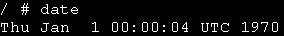
-
Set System Clock
Command:
date MMDDhhmmYYYY.ssMM: month (01-12)
DD: day (01-31)
Hhmm: time (0000-2359)
YYYY: year [optional]
ss: seconds (00-59) [optional]

-
Show RTC Clock
Command:
hwclock
-
Set RTC Clock to System Clock
Command:
hwclock -s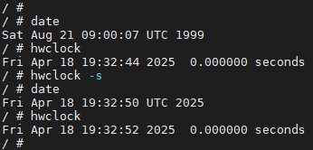
6.5. Sample code
The application can run the /dev/rtc0 file through ioctl to read or set the RTC Clock and Alarm Clock. For details about the code, please refer to driver/sstar/rtc/ut/rtc_ut.c. In the following sections, we will demonstrate how to operate the RTC via rtc_ut.
6.5.1. Read Hareware Clock
Command: ./rtc_ut

6.5.2. Set Hareware Clock
Command: ./rtc_ut -w -s "2021-11-3 20:10:30"
Description: Set RTC Clock to November 3, 2021 20:10:30

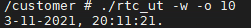
Command: ./rtc_ut -w -o 10
Description: Set RTC Clock to the current time plus 10 seconds
6.5.3. Read Alarm Clock
Command: ./rtc_ut -a

6.5.4. Set Alarm Clock
Command: ./rtc_ut -a -w -s "2021-11-3 20:20:30"
Description: Set RTC Alarm Clock to November 3, 2021 20:20:30

The application will sleep until triggered by the alarm clock.
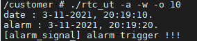
Command: ./rtc_ut -w -a -o 10
Description: Set RTC Alarm time to the current time plus 10 seconds, and be triggerred after ten seconds.
7. API reference
RTC has no open API.
8. FAQ
Q1: Hardware clock stops working
-
Type the command
hwclockmultiple times to confirm whether the clock is beating. If it is beating, it is normal. Otherwise, proceed to the next step -
Read the RTC register multiple times to determine whether bank: 0x34's 0x9&0xA is beating, and take a screenshot to save the register information
-
Check whether the RTC's external crystal oscillator working status and RTC power supply are normal
Q2: Alarm stops working
-
echo [time] > /sys/class/sstar/rtcpwc/alarm_time
-
cat /proc/interrupts
-
Wait for Alarm to be triggered and confirm whether the number of Alarm interrupt triggers has increased
Q3: Abnormal power control scenario
-
Oscilloscope measures RTC_IO4&5 waveforms before and after the problem
-
Confirm whether the behavior of the waveform conforms to the expected power-on and power-off operations.