PMIC Driver Development Guide
REVISION HISTORY
| Revision No. | Description |
Date |
|---|---|---|
| 1.0 | 02/18/2023 | |
| 1.1 | 04/21/2025 |
1. OVERVIEW
The PCUPID development board defaults to using IDAC to control the power supply, while the PCUPID SSZ001A/SSZ001C single board uses PMIC to control the power supply. The PMIC used for PCUPID SSZ001A/SZ001C single board is laiyuan ICP1301, and some customers may wish to use other PMICs instead. If other PMICs are used, the software will adapt to the new PMIC. This article will explain what work needs to be done at the software level after replacing the new PMIC. These tasks can be roughly divided into the following:
-
Ensure that PMIC meets hardware requirements and organize the connection relationship between PMIC power supply pins and SOC pins
-
Develop PMIC power management control driver based on Linux regulator framework
-
Develop RTC driver for PMIC based on Linux RTC framework
-
Power failure and STR operation of the adaptive system
2. KEYWORD DESCRIPTION
-
PMIC
Power Management IC is a specific purpose integrated circuit that functions to manage power and other tasks for the main system.
-
IDAC
DAC generally refers to output voltage type DAC, while IDAC, as the name suggests, outputs current type DAC.
-
Linux regulator framework
The Linux Regulator Framework is designed primarily to provide a standard kernel interface for controlling voltage and current regulators. The purpose is to allow the system to dynamically control the regulator power output to save energy and extend battery life.
-
Linux RTC framework
The Real-Time Clock (RTC) framework in the Linux kernel provides a standardized interface to interact with hardware real-time clocks.
3. PMIC HARDWARE REQUIREMENTS
There are many requirements in terms of hardware, which cannot be stated one by one here. Let's use the following diagram to explain a few key points, which are the key to software development in the future.
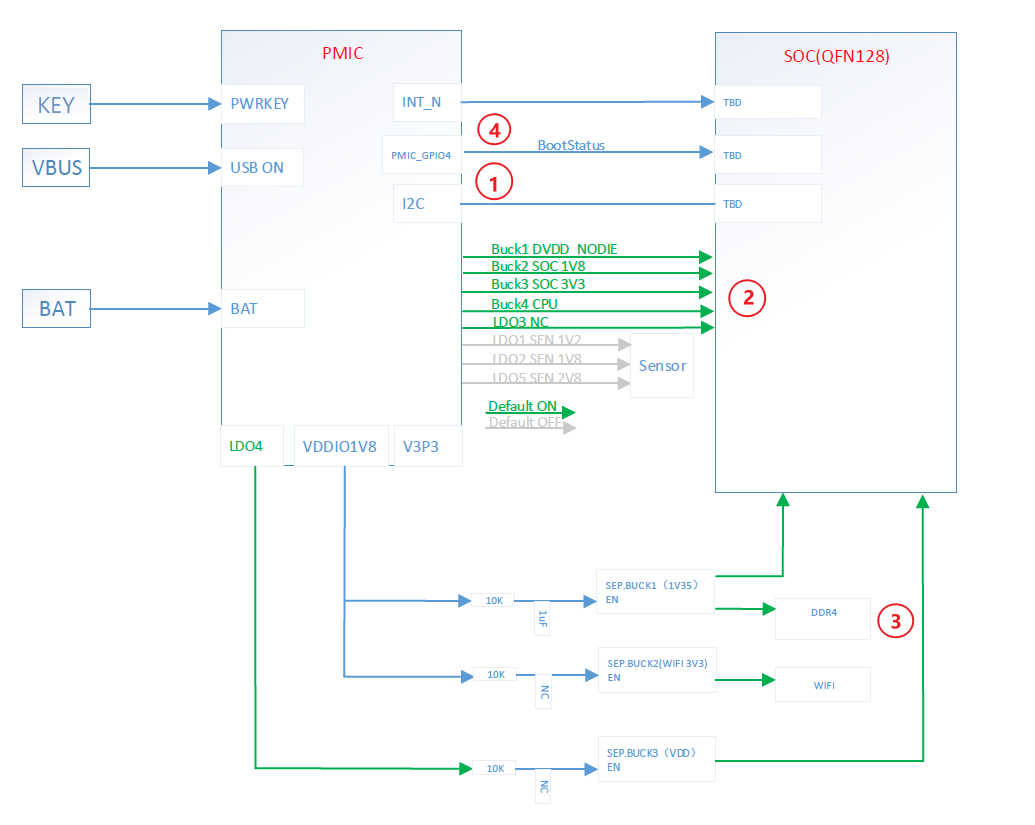
The above figure is the circuit connection diagram of the PMIC and SOC of the PCUPID SSZ001C single board. What needs attention is the circuit corresponding to the red circle above. We will explain it in order of sequence number:
- SOC and PMIC communicate via I2C
- It is necessary to understand which pin of the PMIC powers the SOC's hardware core IP, especially CPU_Power and CORE_power
- When the system enters the STR state, DDR needs power supply, so make sure that the DDR power supply pin still has power during STR.
- Some PMIC boards use the high or low level of a pin on the SOC to determine whether the system is in a cold start or resume process. If this is the case, pay special attention to the selection of this pin on the PMIC and connect it to the GPIO specified by the SOC.
4. Development of PMIC Power Management Control Driver Based on Linux Regulator Framework
4.1 PCUPID VOLTAGE CONTROL FRAMEWORK
Before developing the regulator driver for PMIC based on the Linux regulator framework, let's first understand the voltage regulation framework of the current PCUPID kernel system. PCUPID supports dynamic voltage and frequency regulation of CPU power. The overall framework is shown in the figure below:
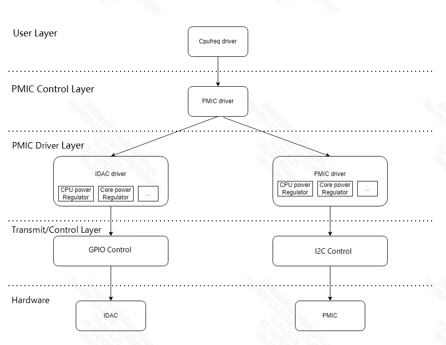
4.1.1 Using Layers
Cpufrequency driver, which receives instructions from the upper layer and dynamically adjusts the CPU voltage according to the frequency at which the CPU needs to run.
Users can adjust the CPU frequency and measure whether the CPU voltage has changed by using the following command:
echo powersave > /sys/devices/system/cpu/cpufreq/policy0/scaling_governor
cat /sys/devices/system/cpu/cpufreq/policy0/scaling_cur_freq

echo performance > /sys/devices/system/cpu/cpufreq/policy0/scaling_governor
cat /sys/devices/system/cpu/cpufreq/policy0/scaling_cur_freq
4.1.2 PMIC Control Layer
This layer mainly implements the following functions:
(1) Implement the following two interfaces so that the upper layer can obtain and adjust CPU voltage through which of these two interfaces
int set_core_voltage(const char *name, VOLTAGE_DEMANDER_E demander, u32 mV)
int get_core_vlotage(const char *name , u32 *mV)
(2) Provide the device node/dev/sstar_pmic so that the user layer can regulate CPU voltage through FHIR commands
(3) Provide debugfs nodes/sys/kernel/debug/star_pmic for user layer settings and voltage viewing
4.1.3 PMIC driver
This layer mainly implements the following functions:
(1) Register the regulator based on the IDAC or PMIC node information in DTS
(2) Implement the regulator_ops called in the regulator. For example:
struct regulator_ops  ICP1301_regulator_ops{
  .set_voltage = icp1301_set_voltage,
  .get_voltage = icp1301_get_voltage,
  .enable     = icp1301_enable,
  .disable     = icp1301_disable
}
After the implementation of regulator_ops, the upper layer selects the regulator corresponding to the circuit to be regulated according to the requirements, and the circuit can be controlled using the following interface:
int regulator_get(dev,  name);
int regulator_set_volatage(regulator, min_uV, max_uV);
int regulator_get_voltage(regulator);
int regulator_put(regulator);
4.1.4 Transport / Control Layer
SOC generally controls IDAC through GPIO and PMIC hardware through IIC. For PMIC, this layer needs to implement the following functions:
(1) Implement and provide IIC interface for system and PMIC communication upwards
4.2 PMIC regulator driver development and adaptation
From the content of the previous chapter, we know that this part of the driver corresponds to the part framed in red in the figure below:
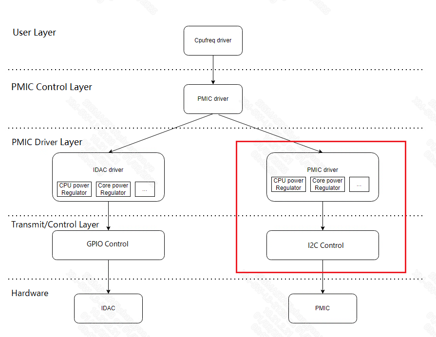
4.2.1 Developing PMIC voltage control driver
The implementation details of this part are different for different PMICs. Generally, the PMIC manufacturer needs to provide the corresponding template code. If there is no corresponding template code, the user needs to implement the corresponding function according to the corresponding PMIC manual. Whether using the template code provided by the PMIC manufacturer or the code written by the user, there are several requirements that need to be implemented during adaptation:
- It is best to communicate between SOC and PMIC through I2C. It is recommended to register the corresponding control code as an I2C driver and export the corresponding read and write interface to facilitate the PMIC regulator driver and RTC driver call
- It needs to be implemented based on the Linux regulator framework. The registered name of the regulator that controls the CPU voltage needs to be "cpu_power"
- The driver needs to have corresponding .suspend() and .resume functions to configure the PMIC before and after the system enters and exits the STR state
- It is best to record all PMIC hardware-related information in the DTS.
The implementation at the code level is closely related to the PMIC itself, so it is impossible to give more detailed explanations. It is recommended that users refer to the codes in the icp1301 directory in the SDK and the node descriptions related to icp1301 in the dts.
4.2.2 Code implantation location and new kernel config
(1) Code storage path
Currently, the PMIC driver code used by the PCUPID board is placed in the kernel/drivers/sstar/pmic/icp1301 directory, so it is recommended that users create a new directory under kernel/driver/sstar/pmic to store the corresponding code.
Directory: kernel/drivers/sstar/pmic/
|---->pmic\
|   ----> Makefile\
|   ----> Kconfig\
|   ----> pmic.c
|   ---->icp1301\
|              -----> icp1301_regulator.c
|              ----->icp1301_core.c
|              ----->icp1301_rtc.c
|              ----->icp1301.h
|      ----->NewPMIC\
|              -----> NewPMIC_regulator.c
|              -----> NewPMIC_core.c
|              -----> NewPMIC.h
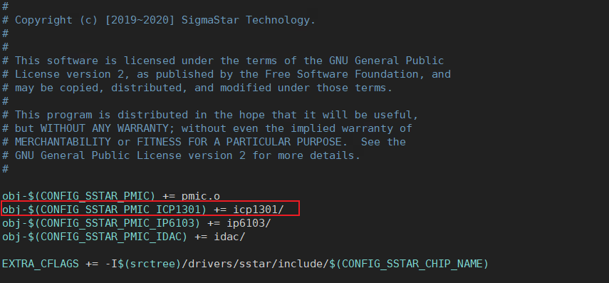
(2) Add kernel config
There is a Kconfig file in the kernel/drivers/sstar/pmic/ directory. After adding PMIC-related driver code, the user needs to add a kernel config. The content can refer to SSTAR_PMIC_ICP1301.
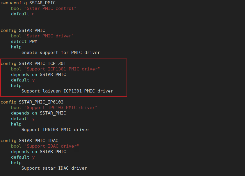
After adding the kernel config, you also need to modify the content of kernel/drivers/sstar/pmic/Makefile and add an obj-$(CONFIG_SSTAR_PMIC_XXXX0 += xxxx/
4.2.3 Self-Test
After the user has developed the PMIC regulator driver, he can perform a self-test using the following command:
a. Adjust voltage command
Command format: echo name value N > /sys/kernel/devugs/sstar_pmic
    Parameter description: input: [name] [voltage] [demander]
            name :      cpu_power/core_power/
            voltage:    unit mv
            demander:   0 - VOLTAGE_DEMANDER_INIT
                        1 - VOLTAGE_DEMANDER_CPUFREQ
                        2 - VOLTAGE_DEMANDER_TEMPERATURE
                        3   - VOLTAGE_DEMANDER_USER
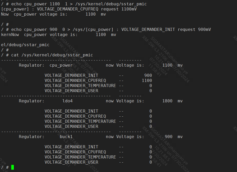
b. Check the voltage command
Command format:cat /sys/kernel/debug/sstar_pmic
5. PMIC RTC driver development and adaptation
5.1 PMC RTC driver development
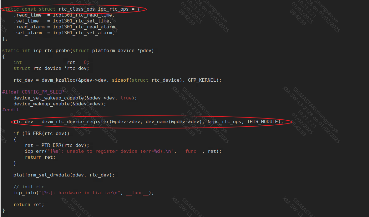
The PMIC RTC driver framework is recommended to meet the requirements of the kernel RTC subsystem, so that it can be easily integrated into the existing kernel system. There are several requirements that need to be met during adaptation:
- It is necessary to be able to obtain and set the hardware time and alarm time of the PMIC RTC, and connect them to the ".read_time", ".set_time", ".read_alarm", and ".set_alarm" in the rtc_class_ops defined in the kernel RTC subsystem respectively.
- Register the rtc_class_ops after the first step through the devm_rtc_device_register of the interface.
- When there is a STR demand, it is also necessary to connect to the "suspend" and "resume" callbacks.
- When using the PMIC manufacturer's RTC driver to replace SSTAR's RTC, you need to turn off the SSTAR RTC related config.
The details are different for different PMICs, and the overall solution can be found in kernel/drivers/sstar/pmic/icp1301/icp1301_core.c file.
5.2 PMIC RTC driver self-test
(1) Reading time
date
(2) Set the time
date -s "2024-08-21 22:18:00" #Set system time
date
(3) Update hardware time to system time
 hwclock -s  # Set system time from hardware clock
 date
(4) Update system time to hardware time
hwclock –w  # Set hardware clock from system time
hwclock -r  # Show hardware clock time
(5) Set an alarm
Set RTC alarm wakeup
echo +n > /sys/class/rtc/rtc0/wakealarm //n is in seconds, indicating that rtc alarm will be triggered after n seconds

Eg: STR 5 seconds wake up
echo +5 > /sys/class/rtc/rtc0/wakealarm
echo mem > /sys/power/state
6. STR and power-off process
Here are some macro processes for system poweroff and STR operations:
(1) Poweroff macro process By default, the system will point the function pointer pm_power_off to the standard power down function psci_Sys_poweroff of PSCI, thereby jumping to TF-a to perform power down operations.
(2) STR macro process
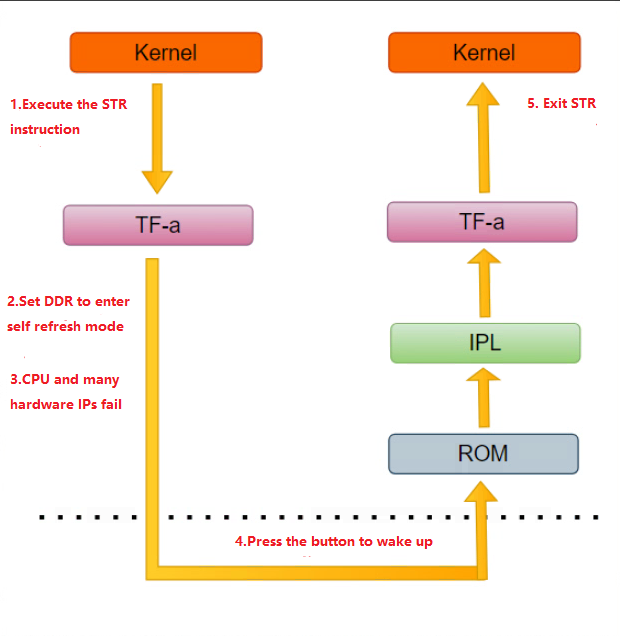
As shown in the above figure, when the system performs STR operations, it will jump from the kernel to TF-a, where it will perform operations such as setting DDR for self refresh and causing the CPU and most hardware to power down.
6.1 Codes involving PMIC in TF-a
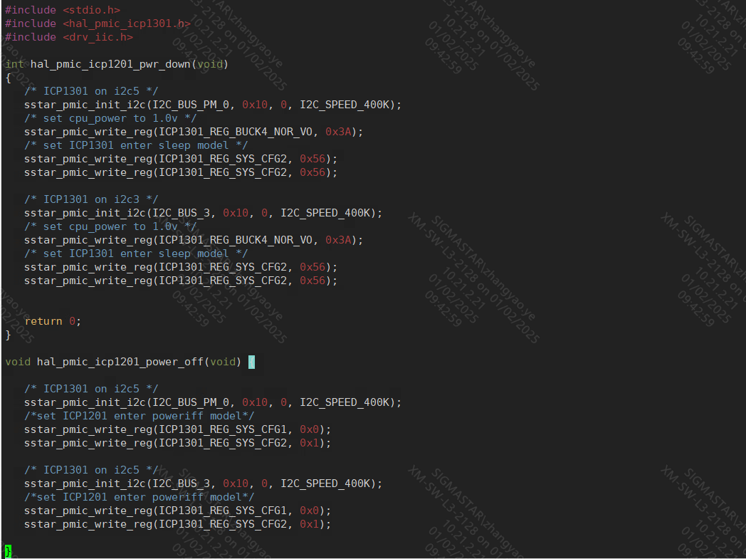
After the system executes the instructions of poweroff or entering STR, the specific commands for power off and sleep operation are issued to PMIC in the TF-a firmware, as shown in the two functions in the following figure. The customer needs to implement these two functions to ensure that they meet the hardware requirements during power off and STR states, which requires specific analysis of the situation. At present, our company has not yet opened the TF-a code. Users can provide the register configuration form for PMIC to perform power-off and sleep operations to FAE, which will then hand it over to our software developers for development.
6.2 PMIC regulator driver suspend/resume function
Because customers use different PMIC pins in different ways, these settings may cause the system to be unable to enter sleep mode. Customers can operate these personalized settings in the probe/suspend and resume functions driven by the PMIC regulator.
6.3 IPL Section
(1) Chip with RTC
Due to the presence of RTC on the single board SOC, the system can determine whether it is a cold start or resume by reading the magic num stored in the RTCPOC register. This type of board does not require users to be related to the content of the IPL section.
(2) Chip without RTC
Due to the absence of RTC on the single board SOC, the wake-up process of STR is distinguished between cold start and resume flow based on the level of a certain GPIO on the SOC. We need to select the GPIO 19 pin on the SOC as this GPIO, so during the sleep to exit STR period, PMIC needs to ensure that the GPIO 19 on the SOC remains high. Note that the GPOE19 pin is always at a low level in other situations.
6.4 STR Self-Test
(1) Poweroff Test Case
 After executing poweroff, the system loses power
 By pressing the PMIC's power key button, the system can be restarted
(2)STR Test Case
 Execute echo mem>/sys/power/state to enter sleep mode, press the PMIC's power key to wake up the system.。

 Set RTC alarm wake-up
 Echo+15>/sys/class/rtc/rtc0/Wakealarm//Trigger RTC alarm after 15 seconds
 Echo mem>/sys/power/state//After executing this command, the system will automatically wake up after 15 seconds
7. FAQ
NA