Wlan User Guide
1. Overview
WLAN is a wireless network technology that defines standards for the physical and data link layers. SigmaStar's PCUPID series chips do not integrate Wi-Fi's MAC and PHY functions internally, requiring an external Wi-Fi chip to control the MAC and PHY. A common use case involves an external Wi-Fi module (a modular hardware circuit that integrates a Wi-Fi chip, radio frequency hardware, and a protocol stack, providing Wi-Fi connectivity to other devices through standard interfaces).
Standard communication interfaces between an external Wi-Fi module and a SoC include the following:
-
SDIO interface
-
USB interface
2. Keyword Explanation
-
Wi-Fi chip: An integrated circuit (IC) that implements Wi-Fi functionality, integrating a MAC controller and a PHY controller. It requires external components such as a radio frequency circuit, power management, and a crystal oscillator to operate and cannot be used independently. Common WiFi chips contain the chip manufacturer's own MCU, which runs core software such as the protocol stack and register configuration.
-
WiFi module: A modular component that integrates a WiFi chip, radio frequency (RF), crystal oscillator, and other hardware, along with the protocol stack, providing WiFi connectivity to other devices through a standard interface. It is a combination of hardware circuitry and software, and is sometimes referred to as just the hardware circuitry.
-
WiFi6: The commercial name for the 802.11ax wireless standard.
3. Functional Description
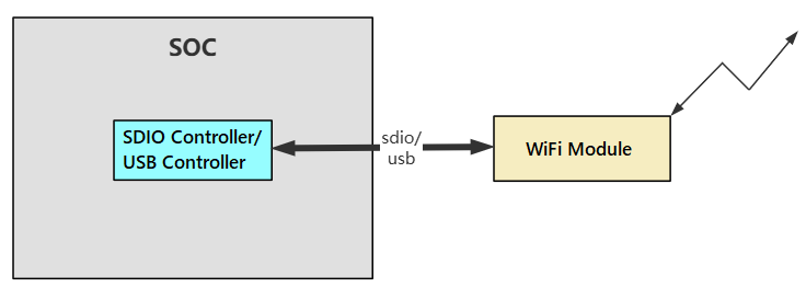
The WiFi technology implementation scheme for the PCUPID series chip public board is shown in the figure. It includes SDIO and USB interfaces for connecting to the WiFi module. Data in memory is sent to the WiFi module via the SDIO or USB interface, and the WiFi module then transmits the data into the electromagnetic environment using its own RF signal. The receiving process is exactly the opposite.
Wi-Fi chips/modules have the following characteristics:
- They do not use the Linux system's native wireless MAC layer protocol stack (i.e., they do not use the mac80211 subsystem). However, they do use the cfg80211 subsystem to complete Wi-Fi module parameter configuration.
- The wireless MAC layer protocol stack is mostly integrated within the Wi-Fi chip (some Wi-Fi chips have MCU functionality and can run the manufacturer's own MAC layer protocol stack code).
- The adaptation logic for the Linux network protocol stack is primarily implemented in the module's driver .ko file.
4. Hardware Connection Introduction
4.1 SoC Hardware Interface Verification
The WiFi module on the PCUPID series chip public board uses both SDIO and USB interfaces. Here, the Comake_Pi_D1 board is used as an example. It uses the USB1 interface, and the USB interface pins are "DP_USB2_P0/1" and "DM_USB2_P0/1."
Note: The USB interface pins are dedicated and do not share other functions. Therefore, you will not find the USB interface pins in the "ARM Tmux" sub-table of the "HW Checklist" table.
4.2 Wi-Fi Module Interface Verification
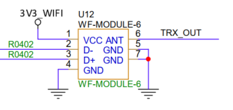
The Comake_Pi_D1 board uses the SSW108ge. The following figure is a wiring diagram of the module. Pay attention to the module's pinout.
4.3 Schematic Connection
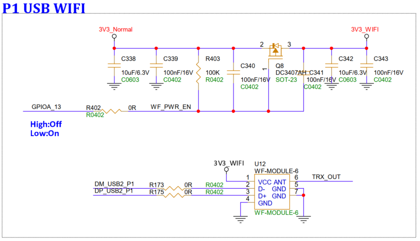
The Comake_Pi_D1 development board connects to the Wi-Fi module via the USB1 port, as shown in the following figure. The two signal lines of the USB1 port are DP_USB2_P1 and DM_USB2_P1.
The Wi-Fi module is powered by 3V3_WIFI. Power is controlled by the GPIOA_13 pin in conjunction with a switching transistor. When GPIOA_13 outputs a low level, the switching transistor turns on, and 3V3_WIFI powers the module.
When using the Wi-Fi module, ensure that power is enabled. To enable default power, configure the GPIOA_13 pin in the kernel device tree (DTS). See the following sections for detailed configuration instructions.
5. Kernel Usage Introduction
5.1 Configuring the SDIO Interface DTS
If your WiFi module uses an SDIO interface, refer to the "SDMMC User Guide" to complete the device tree (DTS) and padmux configuration.
5.2 Configuring the USB Interface DTS
If your WiFi module uses a USB interface, refer to the "USB User Guide" to complete the device tree (DTS) configuration for USB host mode.
5.3 Kernel Config Configuration
Execute make menuconfig in the kernel directory, then enable or disable it. Modify certain configuration items. To save the modified configuration, execute make savedefconfig again, then execute cp <defconfig> <target defconfig>
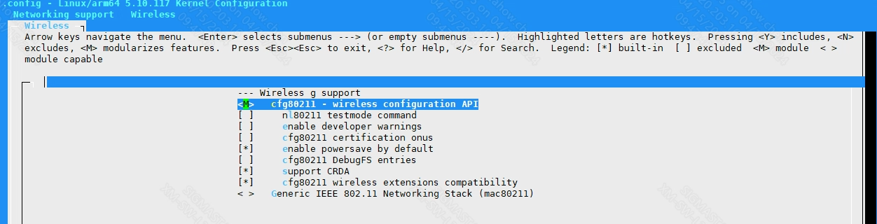
5.3.1 Configuring Wext
Wext stands for Wireless Extension, a standard interface between the kernel's Wi-Fi driver and user-mode processes. The iwpriv command relies on this configuration. WEXT is a technology from the early 2000s and no longer meets modern Wi-Fi requirements. Enable this configuration option as needed.
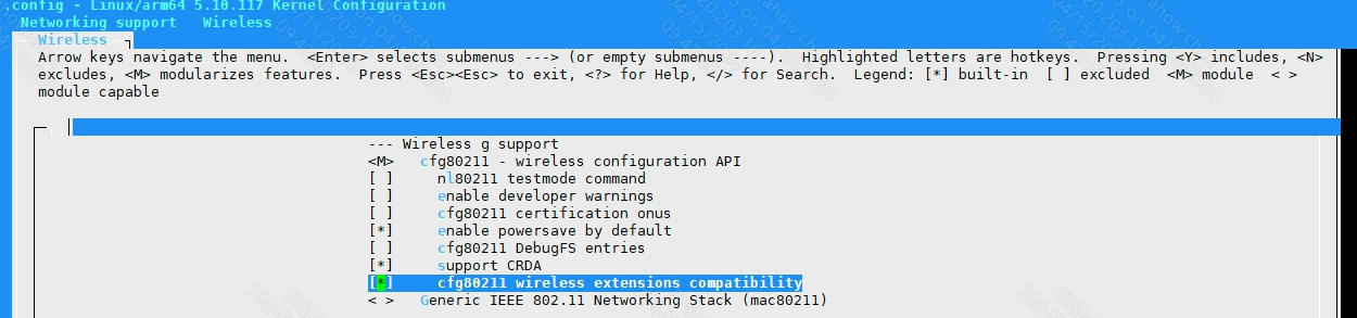
The kernel configuration is as follows:
-*- Networking support  --->
    -*-   Wireless  --->
        <M>   cfg80211 - wireless configuration API
        ...
        [*]     cfg80211 wireless extensions compatibility
5.3.2 Configuring CFG80211
CFG80211 is the standard interface for WIFI drivers and user-mode processes in the kernel. Before CFG80211, it was WEXT, but now more and more people are using CFG80211.
The kernel configuration is as follows:
-*- Networking support  --->
    -*-   Wireless  --->
        <M>   cfg80211 - wireless configuration API
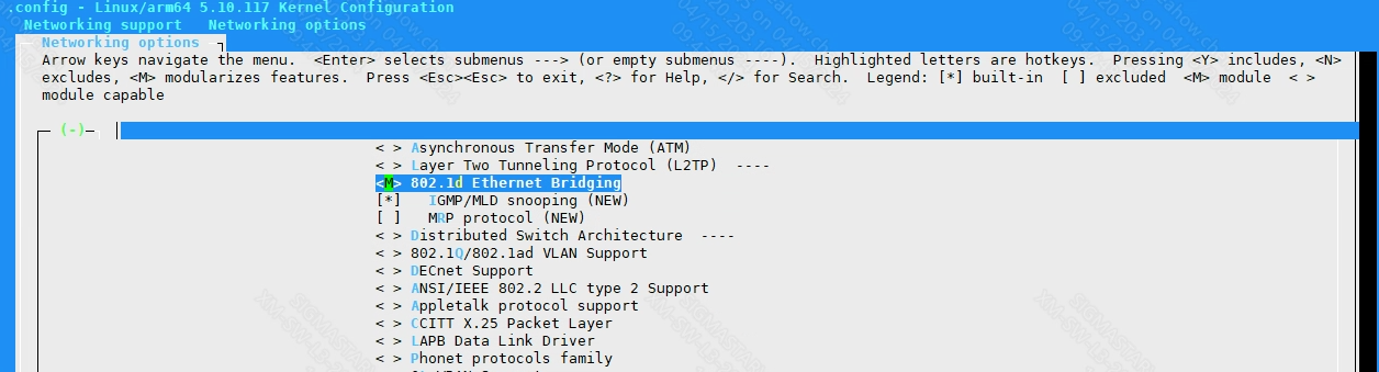
5.3.3 Configuring the bridge
Use wlan and p2p to realize board-side WIFI bridging, the kernel configuration is as follows:
-*- Networking support  --->
    -*-   Wireless  --->
        <M>   cfg80211 - wireless configuration API
Device Drivers  --->
    Generic Driver Options  --->
        [*] Support for uevent helper
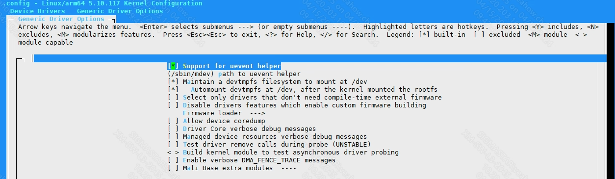
-*- Networking support  --->
    Networking options  --->
        <M> 802.1d Ethernet Bridging
5.4 Loading Related KO Files
5.4.1 Loading SDIO-Related KO Files
SDIO-related KO files are already compiled into the kernel by default and will automatically load and run upon power-up.
- mmc_core.ko
- mmc_block.ko
- kdrv_sdmmc.ko
5.4.2 Loading USB-Related KO Files
For USB host mode, the following KO files must be loaded in order:
- usb-common.ko
- usbcore.ko
- sstar-usb2-phy.ko
- ehci-hcd.ko
5.4.3 Loading Kernel-Related KO Files
The following KO files must be loaded:
- cfg80211.ko
5.4.4 Loading Wi-Fi Module-Related KO Files
Wi-Fi module manufacturers will provide customers with the corresponding driver KO files. The PCUPID series chip reference board provides driver files for the SDIO and USB interfaces, namely ssw102b_wifi_sdio.ko and SSW108GE_wifi_usb.ko.
The Comake Pi D1 development board uses SSW108GE_wifi_usb.ko, which provides the following three functions:
-
MAC layer adaptation: Interfacing with the Linux kernel network protocol stack (e.g., registering network interfaces through the net_device structure to implement protocol conversion for packet transmission and reception).
-
Hardware control: Initializing the WiFi chip (e.g., radio frequency, baseband, firmware loading), and managing hardware parameters such as wireless channel, power, and encryption.
-
Interface control: Implementing communication between the SDIO/USB bus and the WiFi chip (e.g., data frame packetization/unpacking, interrupt handling, and bus timing control).
The Comake Pi D1 development board loads SSW108GE_wifi_usb.ko by default in its startup script.
5.5 Application Layer Calls
After loading the SSW108GE_wifi_usb.ko driver, you can use Wi-Fi functionality normally at the application layer. Common tools include iwconfig, iwlist, wap_supplicant, wap_cli, hostapd, and hostapd_cli.
6. Common Tools
6.1. Usage of wap_supplicant
wpa_supplicant is an independently running daemon process that is used to start the wireless network background service and process the WPA state machine, control commands, driver events, configuration information, etc. in the message loop.
Common command parameters are as follows:
-I <ifname> // Network interface name
-c <conf> // Configuration file name
-C <ctrl_intf> // Control interface name
-D<driver> // Driver type name
-p <driver_param> // Driver parameters
-b <br_ifname> // Bridge interface name
-d // Add debugging information
Example:
ifconfig wlan0 up
mkdir -p /tmp/wifi/run
/customer/wifi/wpa_supplicant -Dnl80211 -i wlan0 -c /customer/wifi/wpa_supplicant.conf -d &
Start the wireless network service, the driver type is nl80211, the network port name used is wlan0, and the configuration file path is /customer/wpa_supplicant.conf. If the configuration file contains hotspot information, initiate a connection.
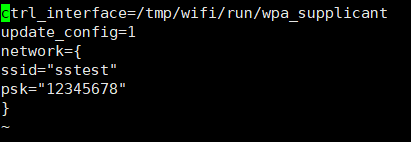
The configuration files are as follows:
ctrl_interface=/tmp/wifi/run/wpa_supplicant
update_config=1
network={
ssid="sstest"
psk="12345678"
}
After successfully connecting to the hotspot:
6.2. Usage of wpa_cli
wpa_cli is the client program that communicates with wpa_supplicant to search, set up, and connect to the network.
Common command parameters are as follows (if the current network interface is wlan0):
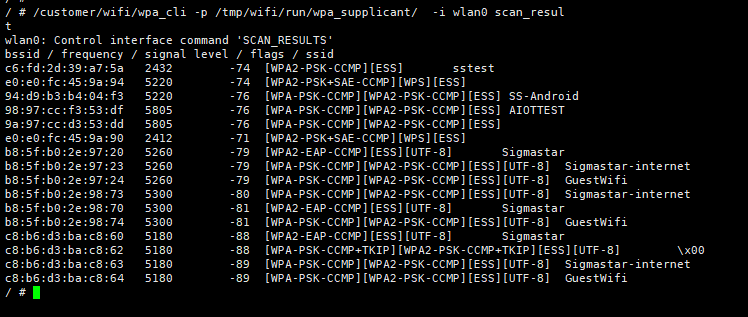
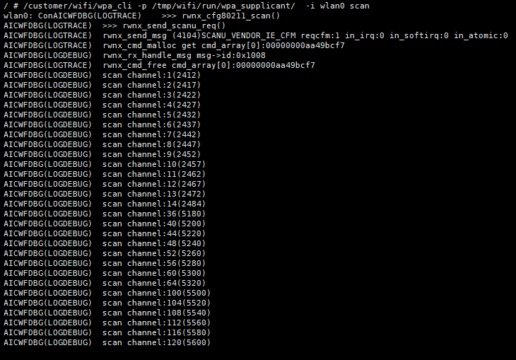
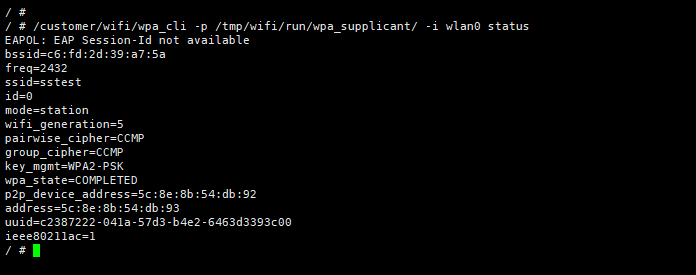
wpa_cli –i wlan0 scan // Scan nearby hotspots
wpa_cli –i wlan0 scan_result // Display scan results
wpa_cli –I wlan0 status // View current connection information
wpa_cli –I wlan0 add_network // Create a new link and return the network id
wpa_cli –I wlan0 set_network <network id> <variable> <value> // Set network parameters, such as ssid, psk, keymgmt
wpa_cli –I wlan0 select_network <network id> // Select the specified network (will disconnect other connections)
wpa_cli –I wlan0 enable_network <network id> // Enable the specified network
wpa_cli –I wlan0 disable_network <network id> // Disable the specified network
wpa_cli –I wlan0 save_config // Save connection information to wpa_supplicant.conf
According to the ctrl_interface set in wpa_supplicant.conf, add the -p option to specify the path, for example:
/customer/wifi/wpa_cli -p /tmp/wifi/run/wpa_supplicant/ -i wlan0 scan
/customer/wifi/wpa_cli -p /tmp/wifi/run/wpa_supplicant/ -i wlan0 scan_result
/customer/wifi/wpa_cli -p /tmp/wifi/run/wpa_supplicant/ -i wlan0 status
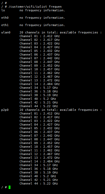
6.3. Usage of iwlist
iwlist is used to analyze the /proc/net/wireless file to obtain information related to the wireless network card.
Common command parameters are as follows (if the current network interface is wlan0):
iwlist wlan0 scanning // Scan the current wireless network
iwlist wlan0 frequen // Display channel information
iwlist wlan0 rate // Display connection speed
iwlist wlan0 power // Display power mode
Example:
/customer/wifi/iwlist scanning
/customer/wifi/iwlist frequen
6.4. Usage of udhcpc
Udhcpc acts as a DHCP client and obtains IP dynamically.
Common command parameters are as follows:
-i <ifname> // Network interface name
-s <script> // udhcpc script
-a // Use arping to verify the provided address
-t <count> // Number of packets sent
-T <time> // Time interval between data packets (default is 3s)
-f // Foreground execution
-b // Background execution
-n // Exit when lease acquisition fails
-q // Exit after obtaining the lease
Example:
udhcpc -q -i wlan0 -s /etc/init.d/udhcpc.script &
Note that the RESOLV_CONF path in udhcpc.script must be filled with a readable and writable path, for example:
-RESOLV_CONF="/appconfigs/resolv.conf"
+RESOLV_CONF="/tmp/resolv.conf"
Note that domain name resolution depends on the compilation chain related libraries. You need to specify LD_LIBRARY_PATH during testing, for example, export LD_LIBRARY_PATH=/customer/libdns:$LD_LIBRARY_PATH. You need to ensure that the /etc path on the board is readable and writable.
6.5. Usage of Hostapd
hostapd is used to make the current device a hotspot, allowing other network devices to access it.
Example:
hostapd -B /customer/wifi/hostapd.conf // -B: execute the daemon process in the background
6.6. Usage of dnsmasq
dnsmasq is a lightweight, easy to configure DNS forwarder and DHCP server. Its purpose is to provide DNS and optionally DHCP to a small network.
Common command parameters are as follows:
-i <ifname> // Network interface name
-C <path> // Specify the configuration file path (default is /etc/dnsmasq.conf)
--no-daemon // Non-background execution
Example:
dnsmasq -i p2p0 --no-daemon -C /customer/wifi/dnsmasq.conf &
6.7. Usage of hostapd_cli
hostapd_cli as a client of hostapd, you need to start the hostapd main program first. After hostapd is started, when running the cli client, it will automatically connect to the currently working hostapd process. After the connection is successful, the cli client can obtain and control the parameters of the hostapd application.
Common command parameters are as follows:
-i <ifname> // Network interface name
-p <path> // Control socket path (default is /var/run/hostapd)
-B // Background execution daemon
Example:
/customer/wifi/hostapd_cli -I p2p0 –p /var/run/hostapd all_sta &
7. WIFI Example
7.1. Loading WIFI driver
First, use insmod to load the WIFI driver. For example, for ssw102b, the corresponding driver is ssw102b_wifi_sdio.ko. Execute the following command:
insmod firmware_class.ko
insmod cfg80211.ko
insmod ssw102b_wifi_sdio.ko
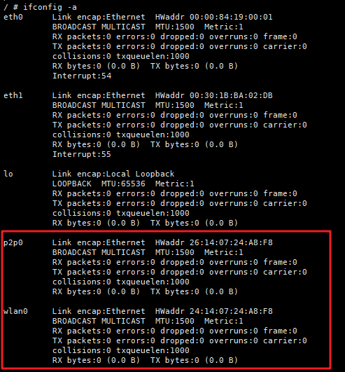
Use ifconfig –a to view, you can see the newly generated wlan0 and p2p0 nodes:
7.2. STA mode test
export LD_LIBRARY_PATH=$LD_LIBRARY_PATH:/customer/wifi
mkdir -p /tmp/wifi/run
chmod 777 /tmp/wifi/run
ifconfig wlan0 up
Create the wpa_supplicant.conf file and edit it as follows. Use the test hotspot as "sstest" and the password as "12345678".
Test the connection:
/customer/wifi/wpa_supplicant -Dnl80211 -i wlan0 -c /customer/wifi/wpa_supplicant.conf -d &
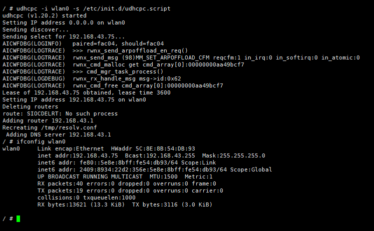
Get IP:
udhcpc -q -i wlan0 -s /etc/init.d/udhcpc.script &
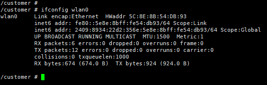
View wlan0 information:
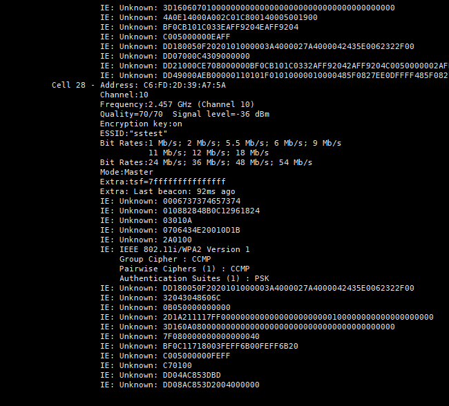
Scan hot spots:
/customer/wifi/iwlist scanning
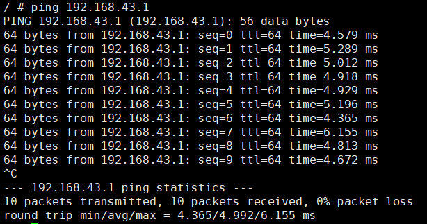
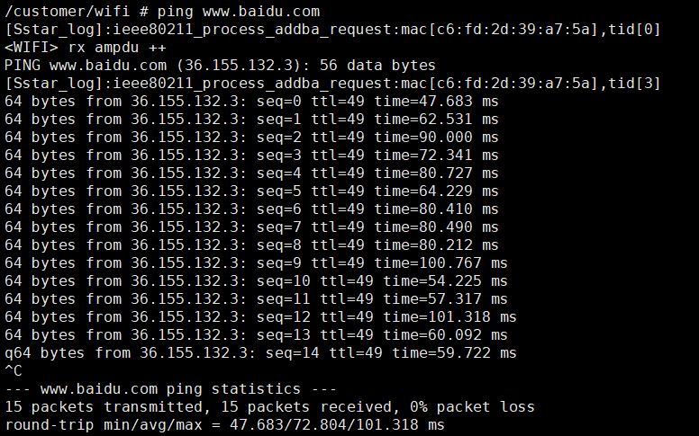
The system will automatically connect to the WiFi network set in wpa_supplicant.conf.
7.3. AP mode test
mkdir -p /var/run/hostapd
mkdir -p /var/wifi/misc
mkdir -p /var/lib/misc
ifconfig p2p0 up
ifconfig p2p0 192.168.1.100 netmask 255.255.255.0
The hostapd configuration file is in /customer/wifi/hostapd.conf, where ssid is the hotspot name of the current device and wpa_passphrase is the connection password of the device. You can modify this file to change the device name and password.
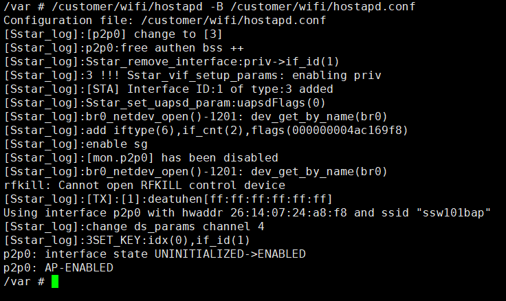
To turn on the hotspot:
./customer/wifi/hostapd -B /customer/wifi/hostapd.conf
./customer/wifi/dnsmasq -i p2p0 --no-daemon -C /customer/wifi/dnsmasq.conf &
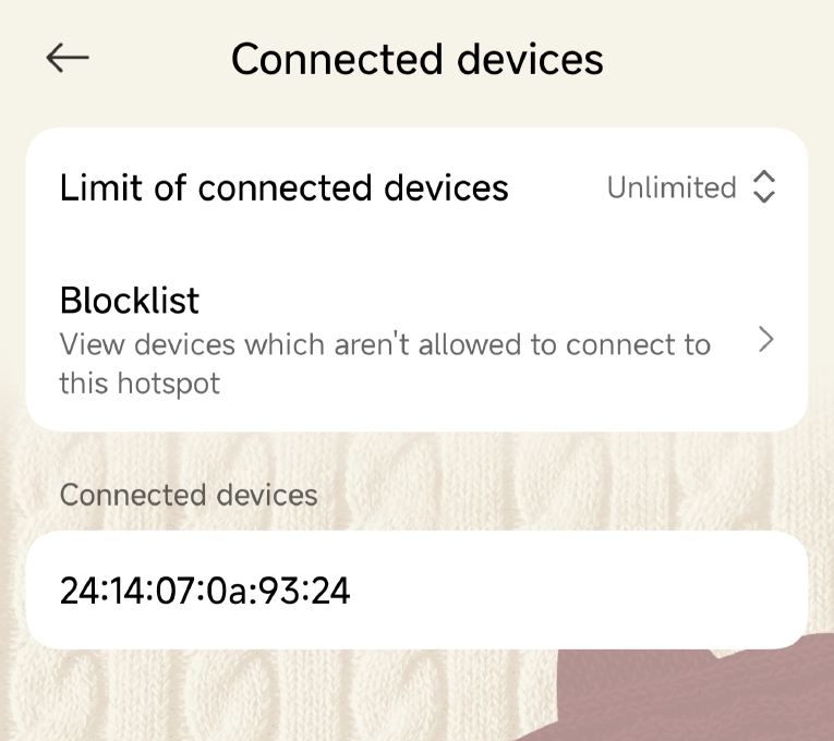
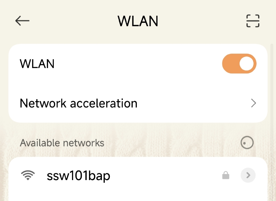
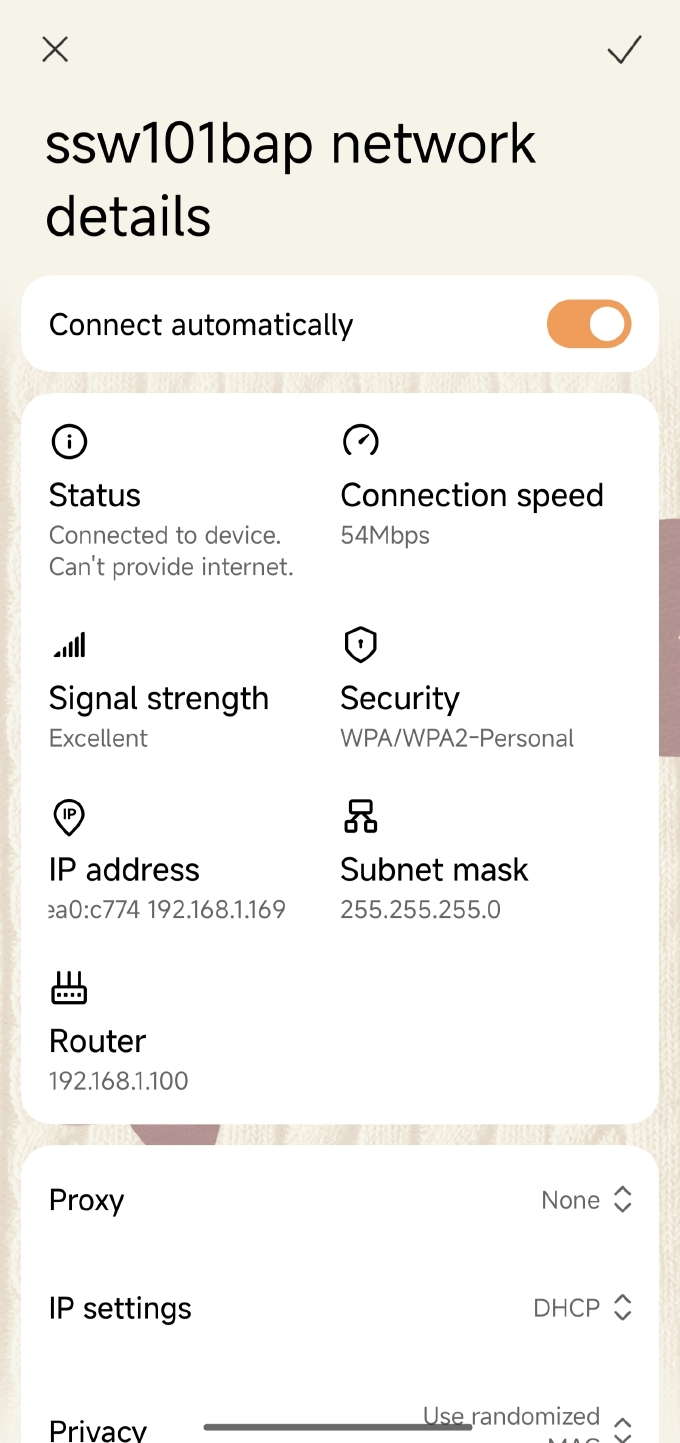
The network device can search for the hotspot "ssw101bap":
Use mobile phone to connect to hotspot
7.4. Bridge mode test
Modify /customer/wifi/wpa_supplicant.conf and add external AP hotspot information:
/ # vi /customer/wifi/wpa_supplicant.conf
ctrl_interface=/tmp/wifi/run/wpa_supplicant
update_config=1

network={
    ssid="sstest"
    psk="12345678"
}
Load the driver:
cd /customer/wifi

mkdir -p /tmp/wifi/run/wpa_supplicant
mkdir -p /var/run/hostapd
mkdir -p /var/wifi/misc
mkdir -p /var/lib/misc
insmod llc.ko
insmod stp.ko
insmod bridge.ko
hostapd.conf needs to add a configuration item:
interface=p2p0 //ssw101/2b uses p2p0 as the AP interface.
bridge=br0 //Fixed
hw_mode=g //Fixed
channel=1
Note: The bridge uses channels, which are consistent on both the front and back ends. Depending on the channel that wlan0 is connected to the ap, fill in the corresponding channel here.
Add environment variables and add the so used by wifi to the system. Usually placed under /customer/wifi export LD_LIBRARY_PATH=$LD_LIBRARY_PATH:/customer/wifi
Initialize the wifi module, refer to the script /customer/wifi/sigma_wifi_init.sh
Note: If you encounter sh: write error: Invalid argument, you can ignore it.
Create a network card bridge:
ifconfig wlan0 up
ifconfig p2p0 up
ifconfig wlan0 0.0.0.0
ifconfig p2p0 0.0.0.0
brctl addbr br0
brctl addif br0 wlan0
brctl addif br0 p2p0
ifconfig br0 up
sta connect to wifi:
/customer/wifi/wpa_supplicant -Dnl80211 -i wlan0 -c /customer/wifi/wpa_supplicant.conf -b br0 &
udhcpc -S /etc/init.d/udhcpc.script -i br0
Enable AP mode:
./hostapd -B /customer/wifi/hostapd.conf
./dnsmasq -i p2p0 --no-daemon -C /customer/wifi/dnsmasq.conf &
AP: SSID:ssw101bap pwd:12345678
If sta can connect to the external network, then after connecting ssw101bap through a PC, you can also connect to the network normally.
Note: If sta is connected to wifi, the error message wlan0 is not sta mode appears, it may be that the wifi driver and kernel do not match. Please find the corresponding wifi module manufacturer to provide a new ko.