PWM USER GUIDE
REVISION HISTORY
| Revision No. | Description |
Date |
|---|---|---|
| 1.0 | 04/09/2025 |
1. OVERVIEW
The PWM (Pulse Width Modulation) module is used to generate pulse width waveforms. It can change the output current and voltage by changing the frequency and duty cycle to achieve functions such as controlling the motor speed and dimming the LCD screen. The SigmaStar PWM module also has a Group function (divided into sync, round, hold, stop), that is, every 4 or 6 channels of PWM can be bound into a group to achieve 4 or 6 channels of PWM synchronous generation or stop.
The relationship between devices and hardware groups is shown in the table below:
| PWM Group | bank addr | Channel |
|---|---|---|
| HW PWM group0 | 1119H | channel 0 ~ 3 |
| HW PWM group1 | 111AH | channel 4 ~ 7 |
| HW PWM group2 | 111CH | channel 8 ~ 11 |
| HW PWM group3 | 112BH | channel 12 ~ 16 |
| HW PM PWM group0 | 1AH | pm channel 0 ~ 1 |
2. FUNCTION DESCRIPTION
dts/dtsi:
Linux device tree files are typically used to describe the peripherals supported by the CPU. The attribute values contained in the peripheral nodes can be used for the configuration of the peripherals.
padmux:
Pin multiplexing is used to connect the functional pins of modules to specific external pins, establishing signal connections.
Dead Time:
The PWM dead time refers to the time interval between two adjacent output signals during the PWM signal switching process. It is used to prevent power switching devices (such as MOSFET or IGBT) from being turned on at the same time during the switching process, thereby avoiding short circuits and damage.
3. Function description
3.1. Overview
-
The number of channels supporting PWM is 20, of which channels 0~17 support joining their own groups, and channels 18~19 do not support the group function. For details, see Corresponding Relationship Between Group and Channel.
-
PWM channels 12~17 support Dead Time setting and brake function with the maximum setting value of (OSCCLK / 0x3FF). For example, if OSCCLK = 12MHz, the range is 0~85250ns.
-
Supports shift functionality, meaning the waveform can have its phase set; the phase will affect the duty cycle, with the actual duty cycle = set duty cycle - phase
-
Support double buffer to prevent the generation of erroneous waveforms, that is, the waveform will wait for the current waveform to be fully generated before updating.
-
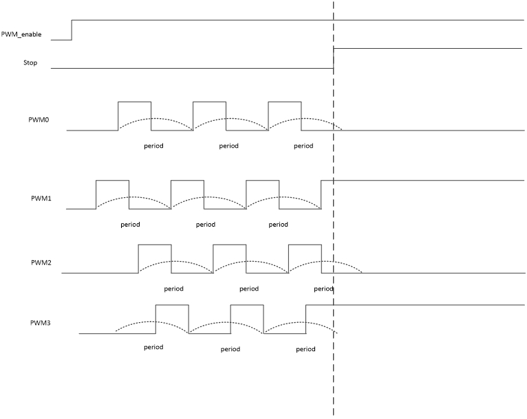
Support sync function, that is, the PWM in the group generates waveforms at the same time, generally a group will contain 4 channels of PWM.
-
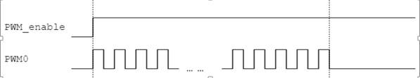
Support round function, that is, the PWM in the same group will stop after generating a specific number of pulses.
-
Support hold function, that is, the PWM in the same group will pause after completing the waveform of the current cycle, which is often used to change the setting of the waveform, and the high and low levels within the pause time can be set.
-
Support stop function, that is, the PWM in the same group will stop urgently.
3.2 Frequency and Duty Cycle
-
Frequency
The number of times a signal changes from high level to low level and then back to high level per second.
-
Duty cycle
The ratio between the duration of high level and the duration of low level.
-
Example description
Assuming that the OSCCLK frequency of PWM is 12M, the frequency range that can be set is: 0.0007Hz~6MHz;
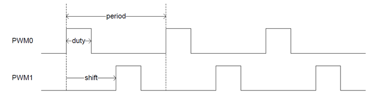
Set PWM0 and PWM1 to waveforms with a frequency of 120Hz and a duty cycle of 25%, and PWM1 has a phase shift of 180° relative to PWM0, then the parameters are configured as follows:
period duty shift PWM0 120Hz 25% 0% PWM1 120Hz 75% 50% Channels 0~17 support OSCCLK(Hz): 86M, 24M, 12M, 6M, 3M, 1.5M, 750K;
channels 18~19 support OSCCLK(Hz): 12M, 6M, 3M;
The operating frequency range is (OSCCLK/2) to (OSCCLK/2^34).Actual working frequency range is as follows:
clk-freq PWM freq range 86MHz 0.0050Hz ~ 43MHz 24MHz 0.0013Hz ~ 12MHz 12MHz 0.0007Hz ~ 6MHz 6MHz 0.00035Hz ~ 3MHz 3MHz 0.00017Hz ~ 1.5Mhz 1.5MHz 0.000087Hz ~ 750KHz 750KHz 0.000044Hz ~ 375KHz The generated waveform is as follows:
3.3. Normal Precision Mode
If Support high precision calculation is not enabled in kernel config, normal precision mode is used. In this mode, the unit of period of PWM is Hz, and the unit of duty cycle is percentage.
Assume that the frequency of PWM0 is set to 10000HZ and the duty cycle is 50%, then:
period = 10000
duty cycle = 50
Take the interface under sys/class/pwm/ as an example, the configuration method is as follows:
1.    # Jump to the PWM control directory
2.    cd sys/class/pwm/pwmchip0/
3.
4.    # Create the PWM0 note
5.    echo 0 > export
6.
7.    # Enter the PWM0 control directory
8.    cd pwm0
9.
10.   # Set the frequency is 10000Hz
11.   echo 10000 > preiod
12.
13.   # Set the duty cycle is 50%
14.   echo 50 > duty_cycle
15.
16.   # Set polarity to reverse (do not set reverse to echo normal > polarity)
17.   echo inversed > polarity
18.
19.   # Enable PWM0
20.   echo 1 > enable
3.4. High Precision Mode
When the Support high precision calculation option is enabled in kernel config, the high precision mode is used. In this mode, the period and duty_cycle of PWM are configured in nanoseconds, so the period and duty cycle values must be calculated first.
Assuming that the PWM0 frequency is set to 10000.5HZ and the duty cycle is 49.5%, then:
period = 10^9 ÷ 10000.5 = 99995
duty cycle = 99995 * 49.5% = 49498
Take the interface under sys/class/pwm/ as an example, the configuration method is as follows:
1.    # Jump to the PWM control path
2.    cd sys/class/pwm/pwmchip0/
3.
4.    # Create the PWM0 note
5.    echo 0 > export
6.
7.    # Enter the PWM0 control path
8.    cd pwm0
9.
10.   # Set the frequency is 10000.5Hz
11.   echo 99995> period
12.
13.   # Set the duty cycle is 49.5%
14.   echo 49498> duty_cycle
15.
16.   # Enable PWM0
17.   echo 1 >enable
It can be seen that the advantage of high precision mode is that parameter settings support decimals.
3.5. GROUP Related Concept
3.5.1 Sync Mode
The sync mode can add each pwm channel to its own Group to achieve the purpose of controlling multiple PWMs at the same time. A Group has 4 pwm channels, and the corresponding relationship between Group and channel is as follows:
| Group | Group Member |
|---|---|
| Group0 | PWM0, PWM1, PWM2, PWM3 |
| Group1 | PWM4, PWM5, PWM6, PWM7 |
| Group2 | PWM8, PWM9, PWM10, PWM11 |
| Group3 | PWM12, PWM13, PWM14, PWM15, PWM16, PWM17 |
You can choose whether to add pwm to the Group in the following ways:
Method 1: Configure group attributes for each channel DTS
The group attribute determines the layout of each channel under /sys/class/sstar/pwm.
Take channel 0 as an example, DTS configures group = <0> and chooses to join group0.
The directory of channel 0 is in the /sys/class/sstar/pwm/group0/ directory:

Take channel 1 as an example, DTS does not configure group attributes and chooses not to add the directories of each channel of group0.
Channel 1 is in the /sys/class/sstar/pwm directory:

Method 2: Use the join interface under /sys/class/sstar/group, echo [channel] [enable] > join
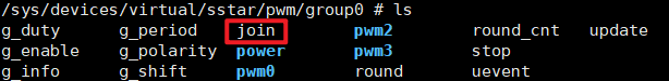
Join: echo 0 1 > join
Exit: echo 0 0 > join
Note: If DTS does not configure the group attribute in method 1, it cannot freely join the group in method 2.
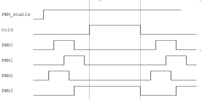
3.5.2 Hold Mode
The Hold function of the group will stop after the PWM completes the waveform of the current cycle and trigger an interrupt. At this time, the configuration of each channel waveform can be changed to keep synchronization. After the modification is completed, the hold function will be turned off and the PWM will regenerate a new waveform. Each group has its own independent hold function.
For example: In high-precision mode, all channels under group0 have output 100HZ, 50% duty cycle, and normal polarity waveforms. On this basis, the period is changed to 1000HZ.
1.    #Jump to the group path
2.    cd sys/class/sstar/pwm/group0
3.
4.    #Set all channels under group0 to output 100HZ, 50% duty cycle, and normal polarity waveforms
5.    echo 10000000  > g_period
6.    echo 7500000   > g_duty
7.    echo 2500000   > g_shift
8.    echo 0         > g_polarity
9.    echo 1         > update // Trigger hold mode
10.   echo 1         > g_enable
11.
12.   #Change the period to 1000HZ
13.   echo 1000000 > g_period
14.   ehco 1         > update // Trigger hold mode
3.5.3 Round Mode
The round function will stop after all channels in the same group complete a certain number of pulses. Each group has its own independent round function.
For example: All channels under group0 have output 1000HZ, 50% duty cycle, normal polarity waveform, and on this basis, they will stop after triggering 100, 200, and 300 pulses respectively.
1.    #Jump to the group path
2.    cd sys/class/sstar/pwm/group0
3.
4.    #Set all channels under group0 to output 1000HZ, 50% duty cycle, and normal polarity waveforms
5.    echo 1000000 > g_period
6.    echo 750000 > g_duty
7.    echo 250000 > g_shift
8.    echo 0      > g_polarity
9.    echo 1      > update
10.   echo 1      > g_enable
11.
12.   #Trigger 100 pulses
13.   echo 100 > round
14.
15.   #Trigger 200 pulses
16.   echo 200 > round
17.
18.   #Trigger 300 pulses
19.   echo 300 > round
3.5.4 Stop Mode
The stop function can stop the PWM in the current group immediately (without waiting for the current cycle to complete) and maintain the level at the end. Each group has its own independent stop function.
For example: Use stop to pause for a period of time and then resume the waveform.
1.    #Jump to the group path
2.    cd sys/class/sstar/pwm/group0
3.
4.    #Set all channels under group0 to output 1000HZ, 50% duty cycle, and normal polarity waveforms
5.    echo 1000000 > g_period
6.    echo 750000 > g_duty
7.    echo 250000 > g_shift
8.    echo 0      > g_polarity
9.    echo 1      > update
10.   echo 1      > g_enable
11.
12.   #Stop waveforms
13.   echo 1 > stop
14.
15.   #Resume waveforms
16.   echo 0 > stop
Note: It is not recommended to set the stop time to be too long, especially when the level maintained after PWM stops is high.
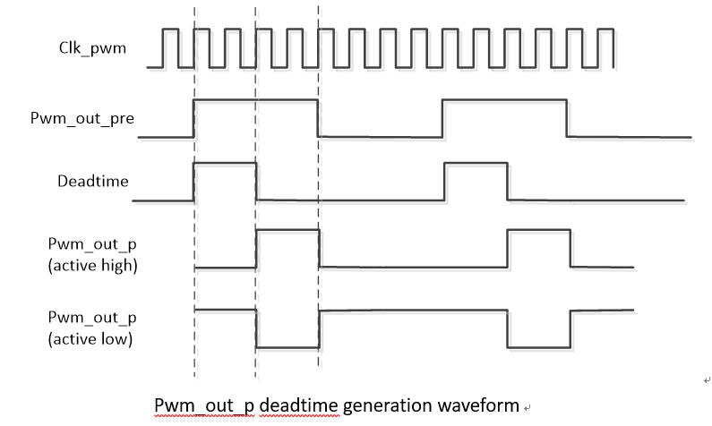
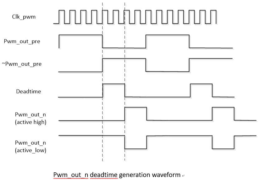
3.6. Dead Time
Dead Time is generated based on two complementary signals. The positive signal generates a delay based on the relative rising edge of the PWM clock, and the negative signal generates a delay based on the relative falling edge of the PWM clock.
4. UBOOT USAGE INTRODUCTION
4.1. Uboot Config Configuration
The configurations that need to be selected when compiling Uboot are as follows:
SigmaStar drivers->

    <*> SigmaStar PWM->

        <*> Support dead time generation  // Whether to support Dead Time setting

        <*> Support high precision calculation // Switch between normal precision and high precision mode
4.2. Configure DTS
The DTS configuration of PWM only needs to configure the following information in the corresponding chipname.dtsi (the number of PWM channels can be selectively configured according to needs, and up to 20 channels can be configured at the same time):
pwm0: pwm@0x1F203200{
    compatible = "sstar,pwm";
    reg = <0x1F203200 0x37>;
    channel = <0>;
    clock-freq = <12000000>;
    status = "okay";
};

pwm12: pwm@0x1F205600 {
    compatible = "sstar,pwm";
    reg = <0x1F205600 0x40>, <0x1F203600 0xC>;
    channel = <12>;
    clock-freq = <12000000>;
    dead-time = <30000 30000>;
    status = "okay";
};
PWM DTS configuration description:
| Attribute | Description | Setting Value | Remark |
|---|---|---|---|
| compatible | Match the driver to register the driver | "sstar,pwm" | Modification prohibited |
| reg | Set the register bank address | / | Modification prohibited |
| channel | Match channel index | 0~19 | No modification required |
| clock-freq | Set OSCCLK | For details, see Frequency and Duty Cycle | Can be modified as needed |
| dead-time | Set dead time | 0~85250ns, effective after pwm enable | Can be modified as needed |
| status | Select whether to enable PWM driver | "ok" or "disable" | Can be modified as needed |
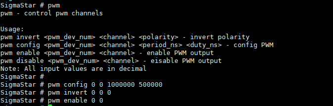
4.3. Uboot Cmd Parameter Description
-
Configure PWM frequency and duty cycle:
pwm config <pwm_dev_num> <channel> <period_ns> <duty_ns> - config PWM
Parameter Description Remark pwm_dev_num Input 0~19 to select the channel you want to configure channel Input 0 period_ns Input the frequency, high precision mode in ns, low precision mode in hz duty_ns Input the duty cycle, high precision mode in ns, low precision mode in hz -
Configure PWM polarity:
pwm invert <pwm_dev_num> <channel> <polarity> - invert polarity
Parameter Description Remark pwm_dev_num Input 0~19 to select the channel you want to configure channel Input 0 polarity Input 0 means normal polarity, input 1 means opposite polarity -
Enable PWM:
pwm enable <pwm_dev_num> <channel> - enable PWM output
Parameter Description Remark pwm_dev_num Input 0~19 to select the channel you want to configure channel Input 0 -
Disable PWM:
pwm disable <pwm_dev_num> <channel> - eisable PWM output
Parameter Description Remark pwm_dev_num Input 0~19 to select the channel you want to configure channel Input 0
4.4. Uboot Cmd Use Case Screenshot
5. KERNEL USAGE INTRODUCTION
5.1. Kernel Config Configuration
The configurations you need to select when compiling the kernel are as follows:
Device Drivers-->
    [*] SStar SoC platform drivers-->
        [*] Sigmastar PWM driver
            [*] Support dead time generation       // Support dead time configuration
            [*] Support high precision calculation // Switch between normal precision and high precision mode
5.2. Configure DTS
The PWM dts configuration only needs to configure the following information in the corresponding chipname.dtsi (the number of PWM channels can be selectively configured according to needs, and up to 20 channels can be configured at the same time):
pwm0: pwm@0x1F203200 {
    compatible = "sstar,pwm";
    reg = <0x0 0x1F203200 0x0 0x40>;
    interrupts=<GIC_SPI INT_IRQ_PWM_GROUP0 IRQ_TYPE_LEVEL_HIGH>;
    clocks = <&CLK_pwm>;
    #pwm-cells = <3>;
    channel = <0>;
    group = <0>;
    clk-select = <0>;
    status = "ok";
};

.......

pwm12: pwm@0x1F205600 {
    compatible = "sstar,pwm";
    reg = <0x0 0x1F205600 0x0 0x40>, <0x0 0x1F203600 0x0 0xC>;
    interrupts=<GIC_SPI INT_IRQ_PWM_GROUP3 IRQ_TYPE_LEVEL_HIGH>;
    clocks = <&CLK_pwm>;
    #pwm-cells = <3>;
    channel = <12>;
    group = <3>;
    clk-select = <0>;
    dead-time;
    idle-status = <0 0>;
    status = "ok";
};
PWM DTS configuration description:
| Attribute | Description | Setting Value | Remark |
|---|---|---|---|
| compatible | Match the driver to register the driver, which must be consistent with the code | "sstar,pwm" | Modification prohibited |
| reg | Set the address of the register bank | / | Modification prohibited |
| interrupts | Specify the hardware interrupt number and attribute to be used | INT_IRQ_PWM_GROUPX | Modification prohibited |
| clocks | Specify the clock source to be used | CLK_pwm or CLK_pm_pwm | Modification prohibited |
| channel | Match channel index | 0~19 | Modification prohibited |
| group | Specify whether to join the group | If this attribute is not configured, the group will not be joined. If the group is joined, configure 0/½/3. For details, see Corresponding Relationship Between Group and Channel | Can be modified as needed |
| clk-select | Used to select the clock gear | pwm0~17 can be selected from 0~6, corresponding to 12M/6M/3M/1.5M/750K/86M/24M respectively; pwm18~19 can be selected from 0~2, corresponding to 12M/6M/3M respectively | pwm0~17 selections must be consistent; pwm18~19 selections must be consistent |
| dead-time | Select whether to support dead time settings | bool | Can be modified as needed |
| idle-status | Select the level status of the dead time waveform when idle | 0- low level; 1- high level | Can be modified as needed |
| status | Select whether to enable PWM driver | "ok" or "disable" | Can be modified as needed |
5.3. PADMUX Configuration
The padmux configuration method of PWM in Uboot and Kernel environment is the same. You only need to add the following code to the corresponding padmux.dtsi according to the selected pin:
PWM PADMUX configuration:
//pwm
<PAD_GPIOC_00   PINMUX_FOR_PWM0_MODE_1    MDRV_PUSE_PWM0>,
<PAD_GPIOC_01   PINMUX_FOR_PWM1_MODE_1    MDRV_PUSE_PWM1>,
<PAD_GPIOC_02   PINMUX_FOR_PWM2_MODE_1    MDRV_PUSE_PWM2>,
<PAD_GPIOC_03   PINMUX_FOR_PWM3_MODE_1    MDRV_PUSE_PWM3>,
<PAD_GPIOC_04   PINMUX_FOR_PWM4_MODE_1    MDRV_PUSE_PWM4>,
<PAD_GPIOC_05   PINMUX_FOR_PWM5_MODE_1    MDRV_PUSE_PWM5>,
<PAD_GPIOC_06   PINMUX_FOR_PWM6_MODE_1    MDRV_PUSE_PWM6>,
<PAD_GPIOC_07   PINMUX_FOR_PWM7_MODE_1    MDRV_PUSE_PWM7>,
<PAD_GPIOC_08   PINMUX_FOR_PWM8_MODE_1    MDRV_PUSE_PWM8>,
<PAD_OUTP_CH0   PINMUX_FOR_PWM9_MODE_1    MDRV_PUSE_PWM9>,
<PAD_GPIOA_00   PINMUX_FOR_PWM10_MODE_2   MDRV_PUSE_PWM10>,
<PAD_GPIOA_01   PINMUX_FOR_PWM11_MODE_2   MDRV_PUSE_PWM11>,
<PAD_GPIOA_02   PINMUX_FOR_PWM12_MODE_2   MDRV_PUSE_PWM12>,
<PAD_GPIOA_03   PINMUX_FOR_PWM13_MODE_2   MDRV_PUSE_PWM13>,
<PAD_GPIOA_04   PINMUX_FOR_PWM14_MODE_2   MDRV_PUSE_PWM14>,
<PAD_GPIOA_05   PINMUX_FOR_PWM15_MODE_2   MDRV_PUSE_PWM15>,
<PAD_GPIOA_06   PINMUX_FOR_PWM16_MODE_2   MDRV_PUSE_PWM16>,
<PAD_GPIOA_07   PINMUX_FOR_PWM17_MODE_2   MDRV_PUSE_PWM17>,
<PAD_PM_I2C_SDA PINMUX_FOR_PM_PWM0_MODE_2 MDRV_PUSE_PWM18>,
<PAD_PM_I2C_SCL PINMUX_FOR_PM_PWM1_MODE_2 MDRV_PUSE_PWM19>,
PADMUX configuration of dead time and its break function:
//dead time
<PAD_GPIOE_17 PINMUX_FOR_PWM_COMP0_MODE_1 MDRV_PUSE_PWMOUT0_P>,
<PAD_GPIOE_18 PINMUX_FOR_PWM_COMP0_MODE_1 MDRV_PUSE_PWMOUT0_N>,
<PAD_GPIOE_23 PINMUX_FOR_PWM_COMP1_MODE_1 MDRV_PUSE_PWMOUT1_P>,
<PAD_GPIOE_24 PINMUX_FOR_PWM_COMP1_MODE_1 MDRV_PUSE_PWMOUT1_N>,
<PAD_GPIOA_00 PINMUX_FOR_PWM_COMP2_MODE_1 MDRV_PUSE_PWMOUT2_P>,
<PAD_GPIOA_01 PINMUX_FOR_PWM_COMP2_MODE_1 MDRV_PUSE_PWMOUT2_N>,
<PAD_GPIOA_08 PINMUX_FOR_PWM_COMP3_MODE_2 MDRV_PUSE_PWMOUT3_P>,
<PAD_GPIOA_09 PINMUX_FOR_PWM_COMP3_MODE_2 MDRV_PUSE_PWMOUT3_N>,
<PAD_EMMC_RST PINMUX_FOR_PWM_COMP4_MODE_1 MDRV_PUSE_PWMOUT4_P>,
<PAD_EMMC_CLK PINMUX_FOR_PWM_COMP4_MODE_1 MDRV_PUSE_PWMOUT4_N>,
<PAD_EMMC_D0  PINMUX_FOR_PWM_COMP5_MODE_1 MDRV_PUSE_PWMOUT5_P>,
<PAD_EMMC_D5  PINMUX_FOR_PWM_COMP5_MODE_1 MDRV_PUSE_PWMOUT5_N>,

//break
<PAD_GPIOA_12 PINMUX_FOR_PWM_INT_MODE_1 MDRV_PUSE_PWMADC_INT>,
<PAD_GPIOA_13 PINMUX_FOR_PWM_INT_MODE_1 MDRV_PUSE_PWMOUT_INT>,
The first column is the pin index number, which can be found in drivers/sstar/inlcude/{chipname}/gpio.h;
The second column is the mode definition. In the hal_gpio_st_padmux_info array in drivers/sstar/gpio/{chipname}/hal_pinmux.c, the multiplexing relationship of all pins is listed. You can query the array to check which multiplexing functions the pin supports;
The third column is the index name of the pin and the matching mode, which can be found in drivers/sstar/include/drv_puse.h.
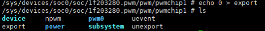
5.4. Introduction to Module Usage
5.4.1 sys/class/pwm
DTS configures N pwm channel nodes, and generates N pwmchip0s in the sys/class/pwm directory. Execute echo 0 > export in the pwmchip0 directory to generate the corresponding pwm0 directory. (Since the npwm value under each pwmchip0 is 1, the parameter passing of export can only be 0). Then, you can configure pwm related attributes in the pwm0 directory: period, duty_cycle, polarity, enable. For details, see Normal Precision Mode or High Precision Mode.


5.4.2. sys/class/sstar/pwm
The sys/class/sstar/pwm directory structure is as follows:
-
Level 1 directory
group0/½/... → Synchronize operations on all channels in the same group
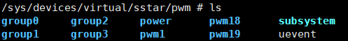
pwm1/... → Operate individually on channels not added to the group

-
Level 2 directory
Take group0 as an example → Set period/shift/duty/polarity/enable for all channels in the same group at the same time, and trigger hold/stop/round functions
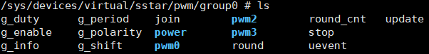
-
Level 3 directory
Take pwm0 as an example → Operate on a channel in the same group, and set period/shift/duty/polarity/enable individually

sys/class/sstar/pwm interface, in the level 2 directory group, you can set all channels belonging to the group uniformly, or you can set the attributes of each channel independently in this directory; in the level 3 directory, you can set the attributes of each channel independently. The difference between setting the attributes of the channel in the level 2 directory and the level 3 directory is as described: After setting the attributes of the channel independently in the level 2 directory, you need to echo 1 > update to trigger the hold function to update the parameters. After setting the attributes of the channel independently in the level 3 directory, it will take effect immediately.
For example: All channels under group0 are synchronized and output 100HZ, 50% duty cycle, and normal polarity waveforms, and then the period of channel0 is changed to 200HZ.
1.    #Jump to the group path
2.    cd sys/class/sstar/pwm/group0
3.
4.    #Set all channels in group 0 to output 100Hz, 50% duty cycle, normal polarity waveforms
5.    echo 10000000  > g_period //The period of all channels in the group is set to 100HZ
6.    echo 7500000   > g_duty
7.    echo 2500000   > g_shift //Duty cycle is (7500000-2500000) / 10000000 = 50%
8.    echo 0         > g_polarity
9.    echo 1         > update //Trigger hold mode
10.   echo 1         > g_enable
11.
12.   #Modify period of channel0 to 200HZ, method 1:
13.   echo 0 20000000 > g_period //Only set the period of channel 0 to 100HZ in the group
14.   echo 1 > update //Trigger hold to update the waveform, still synchronized
15.
16.   #Modify period of channel0 to 200HZ, method 2:
17.   cd /sys/class/sstar/pwm/group0/pwm0
18.   echo 20000000 > period
Under the sys/class/sstar/pwm directory Structure, set dead time:
After DTS enables dead-time, the relevant property files will be generated in the level 3 directory under sys/class/sstar/pwm:

For example: pwm12 outputs a waveform with100 Hz, 50% duty cycle, and normal polarity, and also generates a positive waveform with a dead time of 5000ns and a negative waveform with a dead time of 40000ns.
1.    #Jump to the pwm12 path
2.    cd sys/class/sstar/pwm/group3/pwm12
3.
4.    #Set the parameters to output a waveform of 1000HZ, 50% duty cycle, and normal polarity
5.    echo 1000000  > period
6.    echo 500000   > duty
7.    echo normal   > polarity
8.    echo 1        > enable
9.
10.   #Set the dead time of pwm12, and finally generate a 1000HZ, 45% duty cycle positive waveform and 46% negative waveform
11.   echo 50000 40000 > ddt
12.   echo 1           > ddt_en
Under the above setting conditions, if you need to enable the brake function, you need to enter the following command, and the relevant PIN pins need to be short-circuited to a high level or grounded, take PAD_GPIOA_13 as an example:
echo 0 1 > hw_break //After PAD_GPIOA_13 is grounded, the dead zone waveform stops

echo 1 1 > hw_break //After PAD_GPIOA_13 is connected to a high level, the dead zone waveform stops
5.4.3. IOCTL
In addition to the above-mentioned sysfs interfaces and the standard interfaces provided by the Linux PWM framework, PWM also provides ioctl interfaces, and the usage is as follows.
The header file <drv_pwm.h> is located in the /driver/sstar/pwm directory. The struct pwm_ch_cfg structure is a description of the channel attributes, and the struct pwm_gp_cfg structure is a description of the group attributes.
-
IOCTL_PWM_CHANNEL_CFG: Complete the channel parameter configuration
-
IOCTL_PWM_GET_CHAN_CFG: Get the parameter configuration of the current channel
-
IOCTL_PWM_GROUP_CFG_NR: Complete the parameter configuration of the group
-
IOCTL_PWM_GET_GROUP_CFG: Get the parameter configuration of the current group
-
IOCTL_PWM_GROUP_STOP: Trigger the stop function
-
IOCTL_PWM_GROUP_ROUND: Trigger the round function
#ifndef __DRV_PWM_H__
#define __DRV_PWM_H__

#include <cam_os_wrapper.h>

struct pwm_ch_cfg
{
    u64 duty;      //Set the duty cycle, the actual duty cycle = duty-shift
    u64 shift;     //Set the starting phase
    u64 period;    //Set the period
    u8  enable;    //Enable waveforms
    u32 channel;   //Specify the channel
    u32 polarity;  //Polarity setting: 0-normal, 1-polarity inversion

#ifdef CONFIG_SSTAR_PWM_DDT
    u64 p_ddt;     //Dead time of the positive waveform, in ns
    u64 n_ddt;     //Dead time of the negative waveform, in ns
    u8  ddt_en;    //Enable the dead time
#endif
};

struct pwm_gp_cfg
{
    u64 duty;
    u64 shift;
    u32 group;
    u64 period;
    u8  enable;
    u8  stop_en;   //Enable the stop function
    u32 polarity;
    u32 round_num; //Set the number of pulses in round mode
};

#define PWM_IOC_MAXNR 6

#define IOCTL_PWM_SET_CHAN_CFG_NR  (0)
#define IOCTL_PWM_GET_CHAN_CFG_NR  (2)
#define IOCTL_PWM_SET_GROUP_CFG_NR (1)
#define IOCTL_PWM_GET_GROUP_CFG_NR (3)
#define IOCTL_PWM_GROUP_STOP_NR    (4)
#define IOCTL_PWM_GROUP_ROUND_NR   (6)

#define PWM_IOC_MAGIC           'p'
#define IOCTL_PWM_SET_CHAN_CFG  _IO(PWM_IOC_MAGIC, IOCTL_PWM_SET_CHAN_CFG_NR)
#define IOCTL_PWM_GET_CHAN_CFG  _IO(PWM_IOC_MAGIC, IOCTL_PWM_GET_CHAN_CFG_NR)
#define IOCTL_PWM_SET_GROUP_CFG _IO(PWM_IOC_MAGIC, IOCTL_PWM_SET_GROUP_CFG_NR)
#define IOCTL_PWM_GET_GROUP_CFG _IO(PWM_IOC_MAGIC, IOCTL_PWM_GET_GROUP_CFG_NR)
#define IOCTL_PWM_GROUP_STOP    _IO(PWM_IOC_MAGIC, IOCTL_PWM_GROUP_STOP_NR)
#define IOCTL_PWM_GROUP_ROUND   _IO(PWM_IOC_MAGIC, IOCTL_PWM_GROUP_ROUND_NR)

......

#endif
5.5. Demo code
5.5.1 ioctl demo
#include <autoconf.h>
#include <fcntl.h>
#include <stdio.h>
#include <errno.h>
#include <stdlib.h>
#include <unistd.h>
#include <string.h>
#include <drv_pwm.h>
#include <sys/stat.h>
#include <sys/types.h>
#include <sys/ioctl.h>

int main(int argc, char **argv)
{
    int  ret    = 0;
    int  pwm_fd = -1;
    char path_name[24];

    struct pwm_ch_cfg pwm_channel;
    struct pwm_gp_cfg pwm_group;

    if (argc != 4)
    {
        printf("format: ut_pwm <channel> [channel_id] [enable]\n");
        printf("format: ut_pwm <group>   [group_id]   [enable]\n");
        printf("format: ut_pwm <stop>    [group_id]   [enable]\n");
        printf("format: ut_pwm <round>   [group_id]   [round_num]\n");
        printf("format: ut_pwm <ddt>     [channel_id] [dead_time]\n");
        return -1;
    }

    if (!strcmp(argv[1], "channel"))
    {
        pwm_channel.period   = 1000000;
        pwm_channel.duty     = 500000;
        pwm_channel.shift    = 200000;
        pwm_channel.polarity = 1;
        pwm_channel.channel  = atoi(argv[2]);
        pwm_channel.enable   = atoi(argv[3]);

        snprintf(path_name, sizeof(path_name), "/dev/pwm%u", pwm_channel.channel);
        pwm_fd = open((const char *)(char *)path_name, O_RDWR);
        if (pwm_fd < 0)
        {
            printf("open /dev/pwm%u fail errno:[%d]\n", pwm_channel.channel, pwm_fd);
            return -1;
        }

        ret = ioctl(pwm_fd, IOCTL_PWM_SET_CHAN_CFG, &pwm_channel);
        if (ret < 0)
        {
            printf("pwm channel[%u] set config fail\n", pwm_channel.channel);
            return ret;
        }

        ret = ioctl(pwm_fd, IOCTL_PWM_GET_CHAN_CFG, &pwm_channel);
        if (ret < 0)
        {
            printf("pwm channel[%u] get config fail\n", pwm_channel.channel);
            return ret;
        }

        usleep(500000);
        pwm_channel.duty = 700000;
        ret              = ioctl(pwm_fd, IOCTL_PWM_SET_CHAN_CFG, &pwm_channel);
        if (ret < 0)
        {
            printf("pwm channel[%u] set config again fail\n", pwm_channel.channel);
            return ret;
        }
    }
    else if (!strcmp(argv[1], "group"))
    {
        pwm_group.period   = 1000000;
        pwm_group.duty     = 500000;
        pwm_group.shift    = 200000;
        pwm_group.polarity = 0;
        pwm_group.group    = atoi(argv[2]);
        pwm_group.enable   = atoi(argv[3]);

        snprintf(path_name, sizeof(path_name), "/dev/pwm_group%u", pwm_group.group);
        pwm_fd = open((const char *)(char *)path_name, O_RDWR);
        if (pwm_fd < 0)
        {
            printf("open /dev/pwm-group%u fail errno:[%d]\n", pwm_group.group, pwm_fd);
            return -1;
        }

        ret = ioctl(pwm_fd, IOCTL_PWM_SET_GROUP_CFG, &pwm_group);
        if (ret < 0)
        {
            printf("pwm group[%u] set config fail\n", pwm_group.group);
            return ret;
        }

        ret = ioctl(pwm_fd, IOCTL_PWM_GET_GROUP_CFG, &pwm_group);
        if (ret < 0)
        {
            printf("pwm group[%u] get config fail\n", pwm_group.group);
            return ret;
        }

        pwm_group.duty = 800000;
        usleep(500000);
        ret = ioctl(pwm_fd, IOCTL_PWM_SET_GROUP_CFG, &pwm_group);
        if (ret < 0)
        {
            printf("pwm group[%u] set config again fail\n", pwm_group.group);
            return ret;
        }
    }
    else if (!strcmp(argv[1], "stop"))
    {
        pwm_group.group = atoi(argv[2]);
        snprintf(path_name, sizeof(path_name), "/dev/pwm_group%u", pwm_group.group);
        pwm_fd = open((const char *)(char *)path_name, O_RDWR);
        if (pwm_fd < 0)
        {
            printf("open /dev/pwm-group%u fail errno:[%d]\n", pwm_group.group, pwm_fd);
            return -1;
        }

        pwm_group.stop_en = atoi(argv[3]);
        ret               = ioctl(pwm_fd, IOCTL_PWM_GROUP_STOP, &pwm_group);
        if (ret < 0)
        {
            printf("pwm group[%u] stop config fail\n", pwm_group.group);
            return ret;
        }
    }
    else if (!strcmp(argv[1], "round"))
    {
        pwm_group.group = atoi(argv[2]);
        snprintf(path_name, sizeof(path_name), "/dev/pwm_group%u", pwm_group.group);
        pwm_fd = open((const char *)(char *)path_name, O_RDWR);
        if (pwm_fd < 0)
        {
            printf("open /dev/pwm-group%u fail errno:[%d]\n", pwm_group.group, pwm_fd);
            return -1;
        }
        pwm_group.round_num = atoi(argv[3]);
        ret                 = ioctl(pwm_fd, IOCTL_PWM_GROUP_ROUND, &pwm_group);
        if (ret < 0)
        {
            printf("pwm group[%u] round config fail\n", pwm_group.group);
            return ret;
        }
    }
#ifdef CONFIG_SSTAR_PWM_DDT
    else if (!strcmp(argv[1], "ddt"))
    {
        pwm_channel.channel = atoi(argv[2]);
        snprintf(path_name, sizeof(path_name), "/dev/pwm%u", pwm_channel.channel);
        pwm_fd = open((const char *)(char *)path_name, O_RDWR);
        if (pwm_fd < 0)
        {
            printf("open /dev/pwm%u fail errno:[%d]\n", pwm_channel.channel, pwm_fd);
            return -1;
        }

        ret = ioctl(pwm_fd, IOCTL_PWM_GET_CHAN_CFG, &pwm_channel);
        if (ret < 0)
        {
            printf("pwm channel[%u] get config fail\n", pwm_channel.channel);
            return ret;
        }

        pwm_channel.p_ddt  = atoi(argv[3]);
        pwm_channel.n_ddt  = atoi(argv[3]);
        pwm_channel.ddt_en = 1;

        ret = ioctl(pwm_fd, IOCTL_PWM_SET_CHAN_CFG, &pwm_channel);
        if (ret < 0)
        {
            printf("pwm channel[%u] set ddt config fail\n", pwm_channel.channel);
            return ret;
        }
    }
#endif
    else
    {
        printf("erro pwm command\n");
    }

    close(pwm_fd);

    return 0;
}
5.5.2 Custom API DEMO
Demo code is located in kernel/drivers/sstar/pwm/ut/ut_pwm_module/ut_pwm_module.c, as below
module_param(period, int, S_IRUSR | S_IWUSR | S_IRGRP | S_IROTH);
MODULE_PARM_DESC(period, "Pwm period");
module_param(duty, int, S_IRUSR | S_IWUSR | S_IRGRP | S_IROTH);
MODULE_PARM_DESC(duty, "Pwm duty_cycle");
module_param(polarity, int, S_IRUSR | S_IWUSR | S_IRGRP | S_IROTH);
MODULE_PARM_DESC(polarity, "Pwm polarity");
module_param(enable, int, S_IRUSR | S_IWUSR | S_IRGRP | S_IROTH);
MODULE_PARM_DESC(enable, "Pwm enable");

// Request the pwmdev and check it's state
static int check_pwm_state(unsigned int channel, struct pwm_state pre_state)
{
    gpwm_dev = (struct pwm_device *)CamPwmRequest(channel, "pwm_ut");
    if (IS_ERR_OR_NULL(gpwm_dev))
    {
        pr_err("Failed to request pwm dev - %d\n", channel);
        return -1;
    }
    if (pre_state.period != gpwm_dev->state.period || pre_state.duty_cycle != gpwm_dev->state.duty_cycle
        || pre_state.polarity != gpwm_dev->state.polarity || pre_state.enabled != gpwm_dev->state.enabled)
    {
        pr_err("Incorrect init pwm - %d state\n", channel);
        pr_err(
            "pwm->state.period = %llu\n, pwm->state.duty_cycle = %llu\n,pwm->state.polarity = %d\n, pwm->state.enabled "
            "= %d\n",
            gpwm_dev->state.period, gpwm_dev->state.duty_cycle, gpwm_dev->state.polarity, gpwm_dev->state.enabled);
        return -1;
    }

    return 0;
}

static int __init pwm_customer_init(void)
{
    int                channel = 0;
    struct pwm_state   pre_state;
    struct CamPwmState cam_state;
    pre_state.period     = 500;
    pre_state.duty_cycle = 250;
    pre_state.polarity   = 1;
    pre_state.enabled    = 1;
    if (check_pwm_state(channel, pre_state))
        return -EINVAL;
    cam_state.period   = period;
    cam_state.duty     = duty;
    cam_state.polarity = polarity;
    cam_state.enabled  = enable;
    if (CamPwmConfig(gpwm_dev, CAM_PWM_ALL, &cam_state))
        return -EINVAL;
    pr_info("Pwm test module loaded.\n");
    return 0;
}

static void __exit pwm_customer_exit(void)
{
    if (!IS_ERR_OR_NULL(gpwm_dev))
        CamPwmFree(gpwm_dev);
    pr_err("Pwm test module unloaded.\n");
}
6. API Reference
In addition to the standard PWM framework interfaces, this functional module provides the following interfaces:
| API | Function |
|---|---|
| CamPwmConfig | Set PWM parameters |
| CamPwmRequest | request a PWM handle |
| CamPwmFree | release a PWM handle |
To use these APIs, include the header file kernel/drivers/sstar/include/cam_drv_pwm.h.
The data structures defined therein are as follows:
struct CamPwmState
{
    u64  duty;
    u64  period;
    bool enabled;
    u8   polarity;
};

enum CamPWMArgs
{
    CAM_PWM_PERIOD,
    CAM_PWM_DUTY,
    CAM_PWM_POLAR,
    CAM_PWM_ONOFF,
    CAM_PWM_ALL,
};
6.1. CamPwmConfig
-
Function
Set PWM parameters
-
Declaration
int CamPwmConfig(struct pwm_device *pwm_dev, enum CamPWMArgs args, struct CamPwmState *cam_state);
-
Parameters
Parameter Name Description pwm_dev PWM device structure args Type for setting parameters cam_state Structure representing the target PWM state -
Return Value
Return Value Description 0 Success Negative Failure
6.2. CamPwmRequest
-
Function
Request a PWM handle corresponding to the channel.
-
Declaration
struct pwm_device *CamPwmRequest(int channel, const char *label);
-
Parameters
Parameter Name Description channel PWM channel label Label identifying the PWM device -
Return Value
Return Value Description pwm_dev * Success NULL Failure
6.3. CamPwmFree
-
Function
Release the PWM handle
-
Declaration
void CamPwmFree(struct pwm_device *pwm_dev);
-
Parameters
Parameter Name Description pwm_dev PWM device handle -
Return Value
No return value
7. FAQ
7.1 PWM Interfaces Do Not Exist
-
Check whether the
statusof the DTS PWM node isok. -
Check whether the kernel config is configured, see Kernel Config Configuration for details.
7.2 No PWM Waveform Is Generated after Configuration
Step 1: First confirm whether the measured pin is correct: open the corresponding schematic to confirm, if there is no error, proceed to the next step.
Step 2: Confirm whether the corresponding PWM mode is effective. There are two main reasons for pin multiplexing failure:
Reason 1: The pin is not set to PWM mode. For details on the setting method, see PADMUX Configuration.
Reason 2: A padmux mode with a higher priority than PWM mode is enabled. You can turn on the padmux readback mechanism CONFIG: CONFIG_MSYS_PADMUX during compilation. Its function is to confirm whether the padmux used has been successfully set. After turning it on, enter the following command in user space to check:
echo PAD_PWM0 PINMUX_FOR_PWM0_MODE_1 > /sys/class/sstar/msys/mux_verify

cat /sys/class/sstar/msys/mux_verify
Step 3: Check whether the relevant parameters are set successfully.
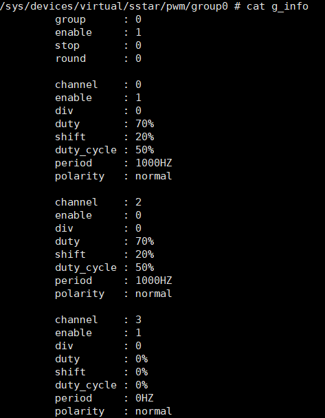
Take pwm group0 as an example, enter the following command to view the parameters:
cd /sys/class/sstar/pwm/group0/

cat g_info
As shown in the figure below, the frequency and duty cycle of channel 0 and channel 2 are set successfully. Channel 0 is enabled and the waveform is output normally. Channel 2 is disabled and no waveform is generated. Channel 3 has no frequency and duty cycle configured.