IR_DebugSop
REVISION HISTORY
| Revision No. | Description |
Date |
|---|---|---|
| 1.0 | 12/04/2024 |
1. Debug Process
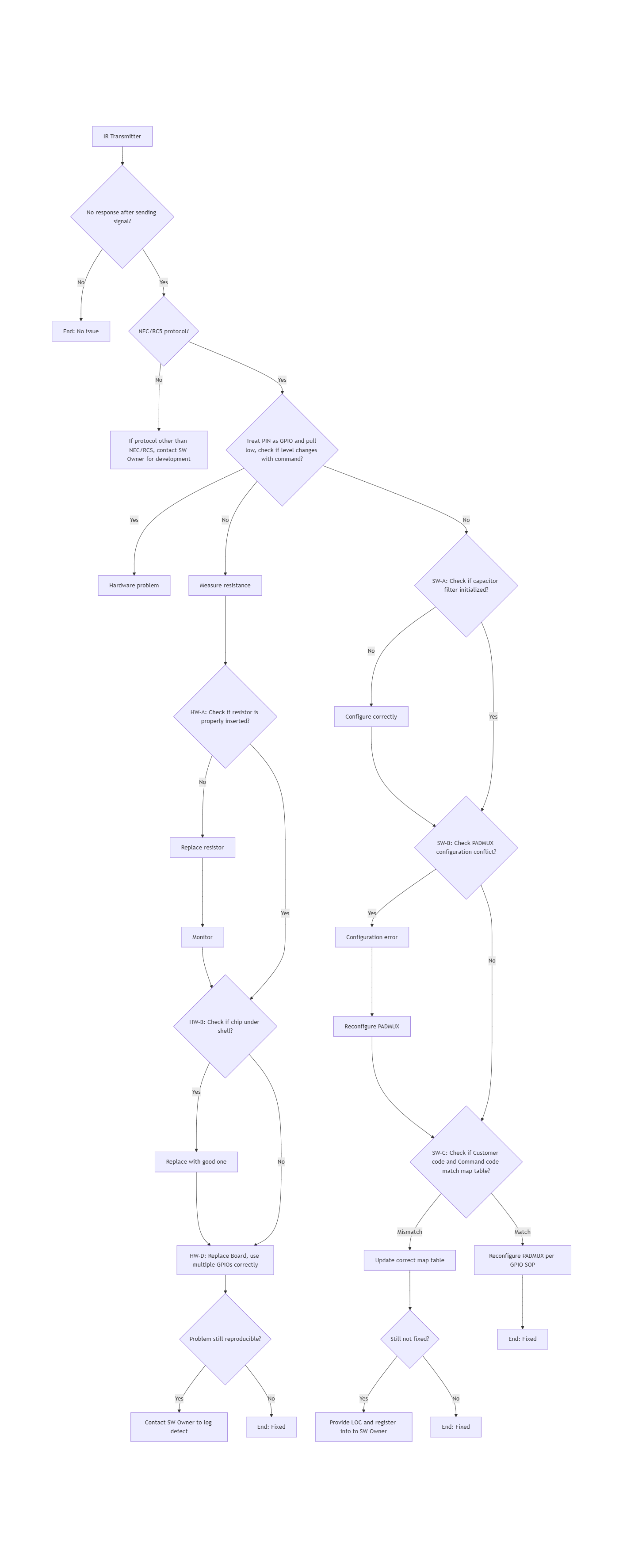
1.1 Debug Flowchart
1.2 Method to Determine Signal Reception Success
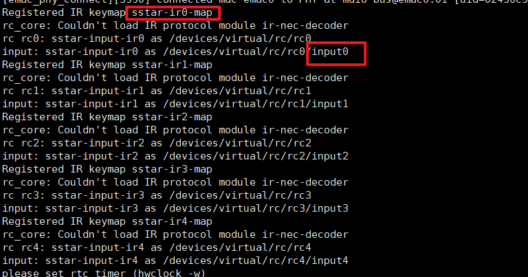
First, check the log to determine the event bound to the IR node, for example, IR0 is bound to event0.
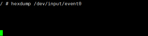
Input the command hexdump /dev/input/event0.
When the signal is not successfully received, there will be no logs, as shown below:
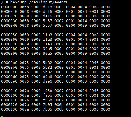
When the signal is successfully received, hexadecimal logs can be seen.
2. Debug Process Explanation
2.1 Protocol Matching
Currently, hardware decoding only supports NEC/RC5 protocols; other protocols need software decoding, which requires adapting a decoder to decode the customer code and command code.
There are two methods to adapt the decoder:
-
Use the native Linux decoder; details can be found in section 5.3 of the document
IR Usage Reference. -
If there is no compatible decoder, please contact FAE development.
2.2 Hardware Issues
When checking for no response after the IR transmitter sends a signal, you can manipulate the registers to set the corresponding PIN as GPIO and pull it high or low (note that some PINs may not have GPIO functionality as the highest priority, in which case you need to clear higher priority settings first). If the actual output level does not change, it can be determined to be a hardware issue, and the following sequence can be used for troubleshooting:
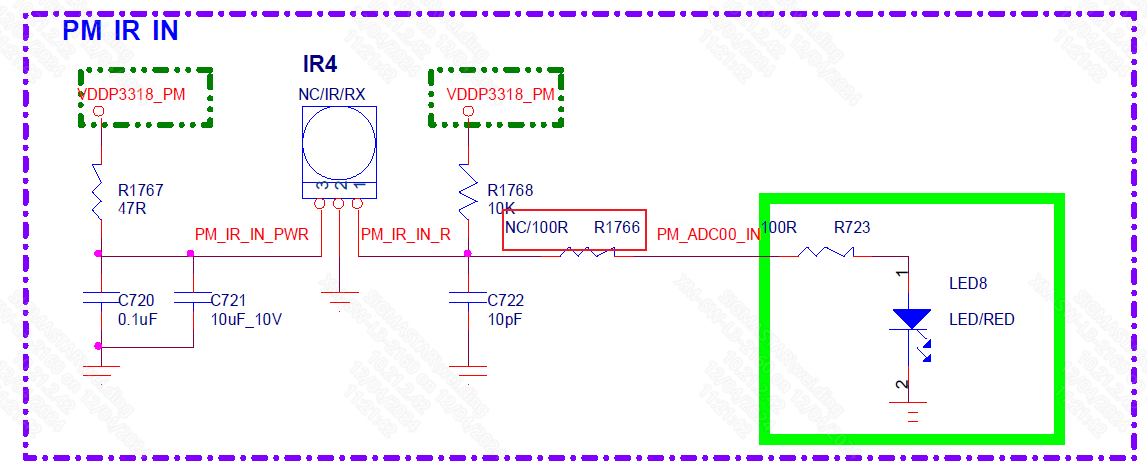
2.2.1 HW-A Check Resistors
Check the schematic for the corresponding PIN to see if there are any soldering issues with the resistors. If there is a soldering issue, the resistor needs to be re-soldered; otherwise, the PIN will not be connected. For example, a 100R resistor needs to be connected at R1766; otherwise, IR signals cannot be received.
2.2.2 HW-B Check Soldering Conditions
If the GPIO can be pulled high or low after replacing the board, it may indicate a cold solder joint on the chip, requiring rework.
2.2.3 HW-C Request Assistance
Contact hardware colleagues for assistance in troubleshooting and re-soldering the chip.
2.2.4 HW-D Defect Reporting
If the GPIO still cannot be pulled high or low after replacing the board, contact FAE to report the issue.
2.3 Software Issues
When determining that it is a software issue, the following sequence can be used for troubleshooting:
2.3.1 SW-A Check IR Register Configuration
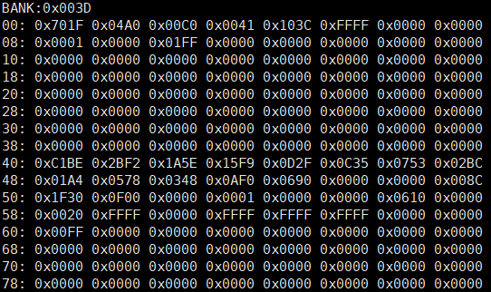
Dump the IR bank and check if the register settings have been initialized.
| Bus | Bank |
|---|---|
| 0 | 0x1671 |
| 1 | 0x1672 |
| 2 | 0x1673 |
| 3 | 0x1673 |
| 4 | 0x3D |
Uninitialized register settings:
Initialized register settings:
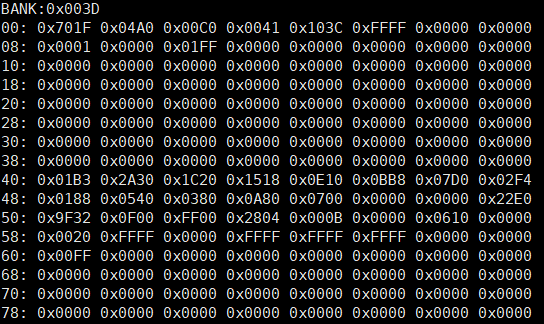
Mainly check the values of offset 0x40~0x4c. If the registers are not initialized, please check if the IR driver is loaded or if the device node is disabled. Refer to sections 5.2 and 5.3 of the document IR Usage Reference.
2.3.2 SW-B Check PADMUX
After confirming the correct configuration of the IR registers, if there is still no response after the transmitter sends a signal, check for conflicts in PADMUX. Refer to the PADMUX conflict check content in Gpio_DebugSop.
2.3.3 SW-C Check if IR Signal Matches Map Table Values
Use a logic analyzer or oscilloscope to capture the signal input to the chip from the IR PIN, as shown below:
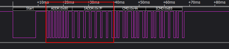
The logic analyzer captures the customer code of the IR input signal as 0x807F and the command code as 0x4A85.
Therefore, the values configured in the map table should be 0x807F4A. Check the configuration of rc-map-table in the dts:
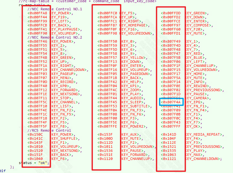
The red box shows the customer code and command code of the IR signal that needs to be configured. If the sampled IR signal is not configured in the rc-map-table, the input subsystem will not report the corresponding key value for that signal. Since 0x807F4A is already configured, and the corresponding key value is KEY_EPPG, every time the IR signal is received, it will report and process the key value KEY_EPPG.
Sometimes, issues such as outdated firmware may cause the rc-map-table running on the board to be inconsistent with what is expected in the code, which can also result in not receiving the IR signal due to mismatched map tables. You can check the actual bound rc-map-table through the following path:
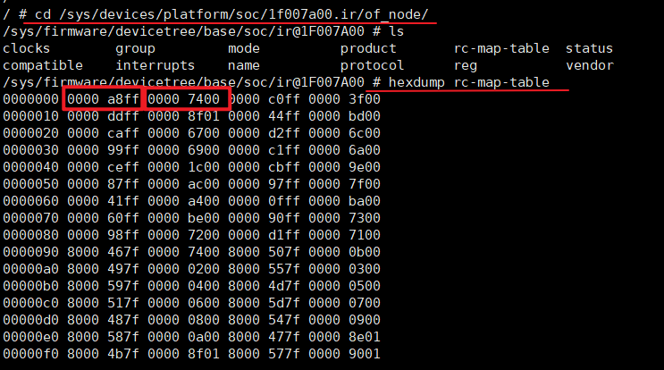
You can compare the first array of the rc-map-table 0x00FFA8 KEY_POWER (macro value 0x74) with the results from the hexdump to see if they match.
2.3.4 SW-D Request Assistance
If the above steps SW-A, SW-B, and SW-C are all checked and OK, please provide relevant LOG and IR BANK information and contact FAE for debugging.