SD EMMC STRESS TEST SOP
REVISION HISTORY
| Revision No. | Description |
Date |
|---|---|---|
| 1.0 | 04/15/2025 |
1. SD EMMC STRESS TEST INTRODUCTION
1.1. Overview
This article is used to guide the stress test of reading, writing and erasing sd/emmc storage under SOC emmc boot. It mainly uses the fio tool and related test interfaces to perform read, write and erase tests on sd/emmc, and hopes to expose potential problems of sd/emmc and judge the health of sd/emmc.
1.2. Environment Preparation Before Testing
Note: The emmc drivers are enabled by default in the Linux emmc boot environment.
1.2.1 Kernel Driver
Before testing, you need to ensure that the kernel supports the emmc driver.
1. make menuconfig
2. # Device Drivers -->
3. #    <*> MMC/SD/SDIO card support -->                   (mmc_core.ko)
4. #        <*> MMC block device driver                    (mmc_block.ko)
5. #    [*] SStar SoC platform drivers -->
6. #        <*> SStar SD/MMC Card Interface Support        (kdrv_sdmmc.ko)
7. #        [ ]     Support SD30
8. #        [*]     Support EMMC50
9. #        [*]     Support SDMMC Command
10.#        [*]       Support SDMMC UT verify
11.#        [*]     SELECT EMMC
1.2.2 Development Board Environment
-
Command check
The test requires the use of the fio tool. The github download address of fio is: https://github.com/axboe/fio. Please compile it according to your own platform.
-
Driver check
After opening and upgrading the driver as described in 1.2.1, check the block device files (/dev/mmcblk0 or /dev/mmcblk1) corresponding to the development board SD and EMMC, enter the /sys/class/mmc_host/mmc0/device/ directory and check whether the eMMC_erase test interface file (this file is not used if emmc erasure is not tested) exists. If it does not exist, check whether the kernel-related options are enabled before and after compiling the code.
-
Test partition
If emmc erasure test is required, it is recommended to create a separate partition for testing.
New partition method:
Testers can use the emmc create command to create a test partition in uboot, for example:
emmc create test1 0x82900000 //Create an emmc partition of size 2G and name test1
**Use mmc part to view the newly created partition:**
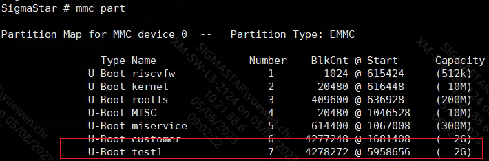
Figure 1-1: Sd_emmc_stress_test-7
You can see that the partition number of partition test1 is 7, and the corresponding test partition file under kernel is /dev/mmcblk0p7.
1.3. FIO Read and Write Test
Mount the partition to be tested before testing. Taking SD as an example, if the block device file of the SD card is /dev/mmcblk1, it can be mounted in the following way:
mkfs.fat /dev/mmcblk1    //Format the SD card with fat file system

mount /dev/mmcblk1 /mnt/ //Mount the SD card to the /mnt/ directory
Use the FIO tool to perform read and write tests on sd/emmc, including sequential write, sequential read, random write and random read. Before testing, create a test file (such as emmc_test) in the partition to be tested. Note that when using FIO for testing, the space reserved for the partition needs to be larger than the set read and write data amount. It is recommended that the test data amount is larger than 1G.
The parameters bs and size can be set according to user needs, and other parameters can be specified as follows.
1.3.1 FIO Parameter Description
filename=/mnt/emmc_test    #Test file name (fill in the absolute path).
direct=1                   #Whether to use directIO, bypass the system's own buffer during the test.
rw=randread                #Test random read I/O.
rw=randwrite               #Test random write I/O.
rw=read                    #Test sequential read I/O.
rw=write                   #Test sequential write I/O.
bs=512                     #The block file size of a single IO is 512 bytes.
size=1G                    #The amount of data read and written by each thread is 1GB.
name=mytest                #The name of the current command task.
thread                     #Use pthread_create to create a thread, and the other is fork to create a process. The overhead of a process is greater than that of a thread, so thread testing is generally used.
ioengine=psync             #Specify the IO engine to use psync mode.
-numjobs=4                 #The number of threads in this test is 4.
-group_reporting           #Display the test results of the task.
1.3.2 FIO Sequential Write Test
Use the following command to test:
(1) The block IO size of a single write test is 512 bytes and the data size is 1G.
fio -filename=/mnt/emmc_test -direct=1 -thread -rw=write -ioengine=psync -bs=512 -size=1G -numjobs=4 -group_reporting -name=mytest
(2) The block IO size of a single write test is 1M and the data size is 1G.
fio -filename=/mnt/emmc_test -direct=1 -thread -rw=write -ioengine=psync -bs=1M -size=1G -numjobs=4 -group_reporting -name=mytest
1.3.3 FIO Sequential Read Test
Use the following command to test:
(1) The block IO size of a single read test is 512 bytes and the data size is 1G.
fio -filename=/mnt/emmc_test -direct=1 -thread -rw=read -ioengine=psync -bs=512 -size=1G -numjobs=4 -group_reporting -name=mytest
(2) The block IO size of a single read test is 1M and the data size is 1G.
fio -filename=/mnt/emmc_test -direct=1 -thread -rw=read -ioengine=psync -bs=1M -size=1G -numjobs=4 -group_reporting -name=mytest
1.3.4 FIO Random Write Test
Use the following command to test:
(1) The block IO size of a single write test is 512 bytes and the data size is 1G.
fio -filename=/mnt/emmc_test -direct=1 -thread -rw=randwrite -ioengine=psync -bs=512 -size=1G -numjobs=4 -group_reporting -name=mytest
(2) The block IO size of a single write test is 1M and the data size is 1G.
fio -filename=/mnt/emmc_test -direct=1 -thread -rw=randwrite -ioengine=psync -bs=1M -size=1G -numjobs=4 -group_reporting -name=mytest
1.3.5 FIO Random Read Test
Use the following command to test:
(1) The block IO size of a single read test is 512 bytes and the data size is 1G.
fio -filename=/mnt/emmc_test -direct=1 -thread -rw=randread -ioengine=psync -bs=512 -size=1G -numjobs=4 -group_reporting -name=mytest
(2) The block IO size of a single read test is 1M and the data size is 1G.
fio -filename=/mnt/emmc_test -direct=1 -thread -rw=randread -ioengine=psync -bs=1M -size=1G -numjobs=4 -group_reporting -name=mytest
1.3.6 FIO Test Result Analysis
Errors can be ignored:
fio:cache invalidation of /mnt/emmc_test fail:Invalid argument
Test result example:
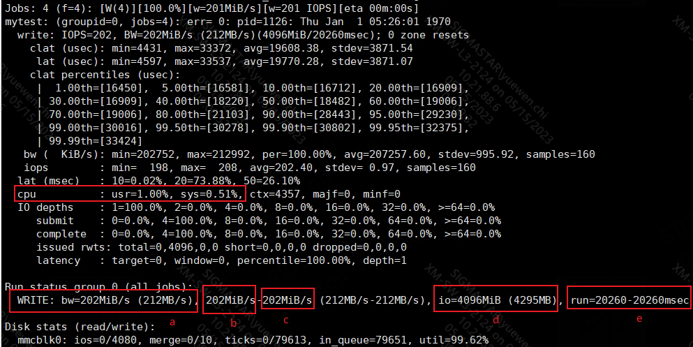
Figure 1-2: Sd_emmc_stress_test-8
Testers mainly focus on whether the parameter data in the red box is abnormal:
cpu: The proportion of user (usr) time and system (sys) time.
bw: Total bandwidth (a), minimum bandwidth (b) and maximum bandwidth ©, all of which are 202M/S here. (The numbers in brackets are in the form of powers of 10).
io: The cumulative I/O size executed by all threads in this group (d), here the four threads cumulatively write 4096M (The numbers in brackets are in the form of powers of 10).
run: The minimum and longest running time in this group of threads (e), here the running time is 20.26 seconds.
1.3.7 CPU STRESS TEST
In addition to the above conventional FIO test, you can simulate the CPU busy state to perform FIO test.
How to use cpu_loading:
echo "loading 0 80 4" > /sys/devices/virtual/sstar/msys/cpu_loading
Parameter description:
-
The first %d represents the total number of running milliseconds. When the input is 0, it means there is no time limit.
-
The second %d represents the required %CPU occupancy value. The set value is the lower limit. 80 means the minimum 80%, which does not necessarily remain at 80% (0< num <= 100: in milliseconds, the percentage of time within one millisecond is occupied, and the rest of the time is dormant).
-
The third %d indicates whether to start the run and the run mode (use 4 when testing, and 0 means to turn off the program run).
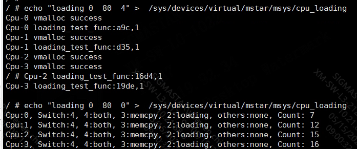
Figure 1-3: Sd_emmc_stress_test-9
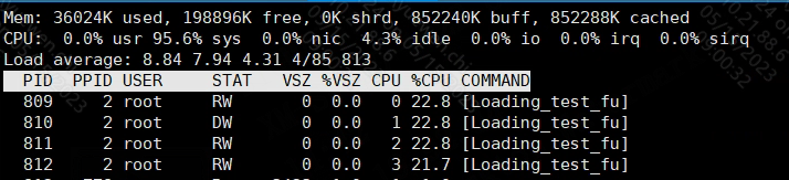
Figure 1-4: Sd_emmc_stress_test-10
Note: In the case of multiple cores, the %CPU displayed by using the top command is the average value of multiple cores. It needs to be multiplied by the number of cores to get the actual occupancy rate of a single-core CPU.
The CPU occupancy rate can be set according to the actual business situation of the user, to simulate whether FIO reads and writes emmc normally when the CPU is busy. FIO read and write tests can be performed after cpu_loading is enabled.
1.3.8 BIST Bandwidth Test
In addition to the CPU stress test described in Section 1.3.7, BIST can be enabled to perform DDR stress test.
How to use BIST:
echo loop rw all > /sys/devices/system/miu/miu0/bist;
By using the above command, bist will occupy the maximum bandwidth for accessing DDR. FIO test can be performed in this mode.
Shut down BIST:
echo stop all > /sys/devices/system/miu/miu0/bist;
You can increase the BIST UTIL occupancy. When cmd_mode=0 is the default, UTIL occupies 84%; when cmd_mode=15, UTIL occupies 98%. Please shut down bist first and then set it.
echo cmd_mode 15 > /sys/devices/system/miu/miu0/bist;
Note: When cma_alloc fails, you can increase cma size in bootargs.
1.4. EMMC Erase Test
The erase test will erase the partition data. It is recommended to create a separate partition for testing. For partition creation methods, see Section 2.2. If you do not want to create a new partition, you can skip the erase test.
How to use eMMC_erase:
cd /sys/class/mmc_host/mmc0/device/
echo "0x5AEC00 0x414800" > eMMC_erase
Parameter description:
-
The first %x indicates the starting address of the partition, in blocks (hexadecimal).
Note: You can get the starting address of the partition through cat /sys/block/mmcblk0/mmcblk0p7/start command.

Figure 1-5: Sd_emmc_stress_test-11
Use a calculator to convert 5958656 to hexadecimal 0x5AEC00.
-
The second %x indicates the size to be erased, in blocks (hexadecimal).
Note: Here 0x414800 means to erase the entire partition, and the partition size can be obtained through cat /sys/block/mmcblk0/mmcblk0p7/size command.
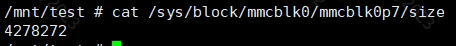
Figure 1-6: Sd_emmc_stress_test-12
Use a calculator to convert 4278272 to hexadecimal 0x414800.
If you need to perform erase tests repeatedly, you can reformat the partition before each erase to ensure that the erase action will be executed by the emmc device. Formatting method: mkfs.ext4 /dev/mmcblk0p7, enter y during the process.
1.5. Vbs Script to Monitor Test Results
If testers need to automatically monitor whether the stress test results are normal, they can use xshell to run the vbs monitoring script provided below:
Sub Main
    Dim waitStrs, result
    Dim i, testCount

    i = 0
    testCount = 172800 '48h'
    waitStrs = Array("DumpReg")

    Do While i < testCount

        result = xsh.Screen.WaitForStrings(waitStrs, 1000)
        If result = 1 Then
            xsh.Screen.Send chr(3)
            xsh.Screen.Send(VbCr)
            xsh.Screen.Send("ps w | grep emmc_stress_test | grep -v ""grep"" | awk '{printf $1}' | xargs kill >/dev/null 2>&1")
            xsh.Screen.Send(VbCr)
            xsh.Screen.Send(VbCr)
            xsh.Screen.Send("emmc stress test fail!")
            exit sub
        else
            i = i + 1
        End If
    Loop

    xsh.Screen.Send chr(3)
    xsh.Screen.Send(VbCr)
    xsh.Screen.Send("ps w | grep emmc_stress_test | grep -v ""grep"" | awk '{printf $1}' | xargs kill >/dev/null 2>&1")
    xsh.Screen.Send(VbCr)
    xsh.Screen.Send(VbCr)
    xsh.Screen.Send("emmc stress test success.")
End Sub
Users can modify the test time in the script as needed. If the stress test script runs in the background, rename the stress test script to emmc_stress_test.sh before running it. The vbs monitoring script will stop the stress test script running at the end.
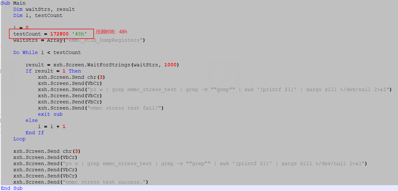
Figure 1-7: Sd_emmc_stress_test-13
Run this script before starting the stress test, open the tool options of xshell, and select the script file to run:
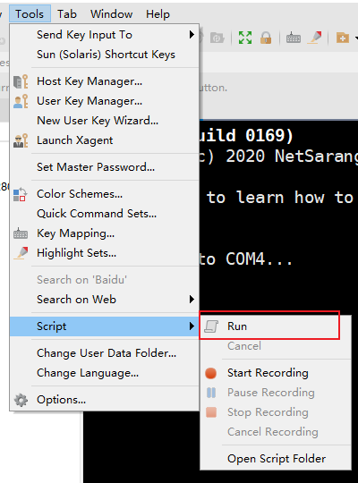
Figure 1-8: Sd_emmc_stress_test-14
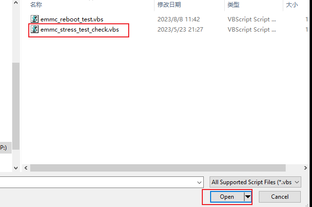
Figure 1-9: Sd_emmc_stress_test-15
After the script runs, it will monitor whether the driver reports eMMC_FCIE_DumpRegisters related errors during the stress test. If this error is detected, the stress test will be stopped and "emmc stress test fail!" will be printed. If no error is detected within the monitoring time, the stress test will also be stopped and "emmc stress test success." will be printed.
2. EMMC POWER-OFF PROTECTION STRESS TEST INTRODUCTION
2.1. Overview
This section is used to guide the stress test of the eMMC Power Save Mode (PSM) function, simulate the actual application scenario, and verify the system stability in a stress test environment with random power on and off. The whole process is automated.
2.2. Test Environment Preparation
2.2.1 Hardware Environment
-
EVB development board (SAR1 pin needs to be turned on to support SAR detect function)
-
Relay control module
-
2 12V power adapters (one for the development board; the other for the relay control module)
-
1 serial port module
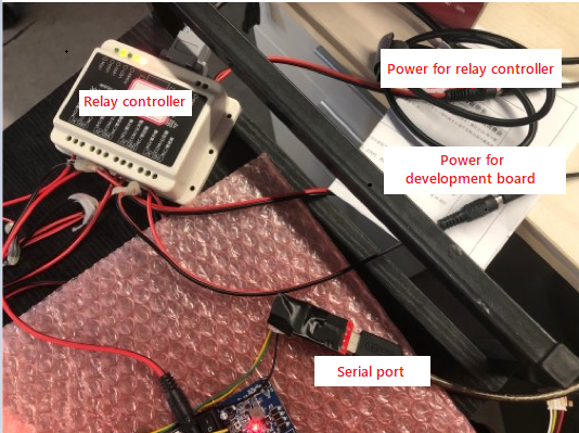
Figure 2-1: Sd_emmc_stress_test-16
2.2.2 Test Principle
-
FIO tool for sequential reading and writing.
-
Python serial module programming to control the relay to power on and off randomly.
-
EMMC driver power-off protection function.
2.3. Test Flow
2.3.1 Pure Linux
-
The development board uses the emmc boot method to enter uboot and create a test partition of about 4GB, as shown in the figure:
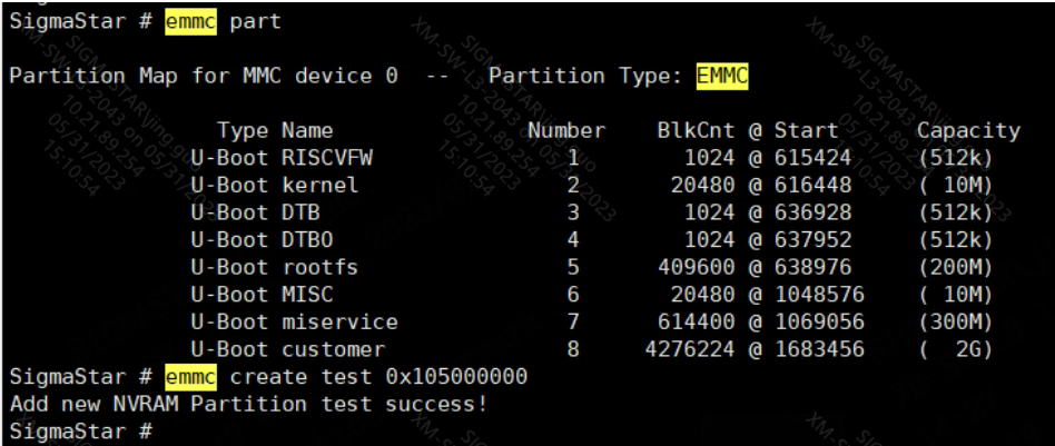
Figure 2-2: Sd_emmc_stress_test-17
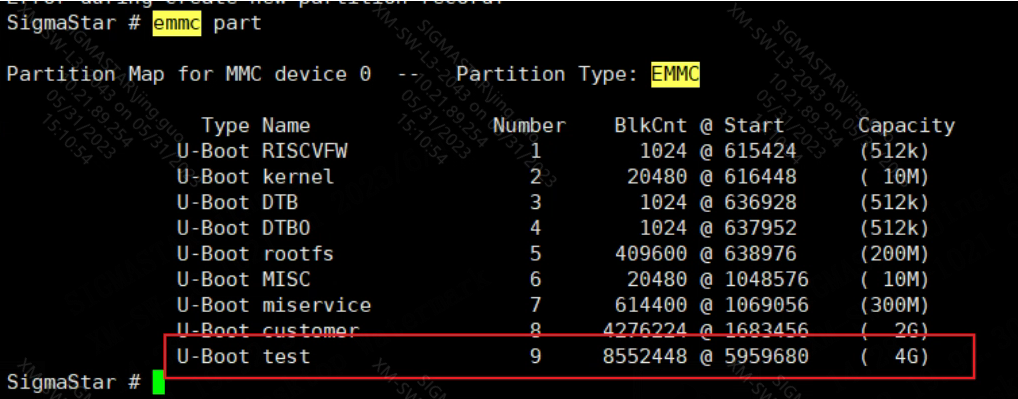
Figure 2-3: Sd_emmc_stress_test-18
-
After re-entering the kernel, format the newly created partition as ext4 file system and mount it at /mnt.
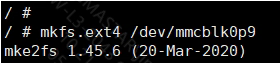
Figure 2-4: Sd_emmc_stress_test-19
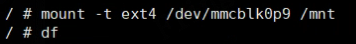
Figure 2-5: Sd_emmc_stress_test-20
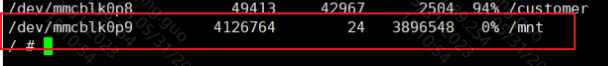
Figure 2-6: Sd_emmc_stress_test-21
-
After mounting the test partition, configure the network parameter information, enter the /mnt path, Put fio and the testcheck.sh script file in the attachment emmc_voltage_drop_test.zip into the path. Remember to dos2unix testcheck.sh and give execution permissions +x to fio and testcheck.sh at the same time.
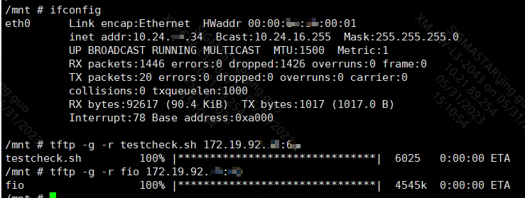
Figure 2-7: Sd_emmc_stress_test-22
-
Change /etc/init.d/rcS as follows so that the stress test script can be automatically executed after each power-on and power-off.
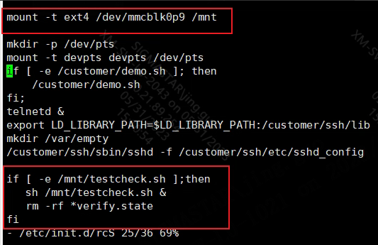
Figure 2-8: Sd_emmc_stress_test-23
2.3.2 Random Power on and Power off
The serialControl.py in the attachment is a python script that controls the random power on and off of the relay. You can execute it directly on the PC: python serialControl.py. The power-on time is an integer in the range of [10s, 600s]. The only thing to note is that the port number in the script needs to be based on the actual allocation of the relay controller when connected to the PC.
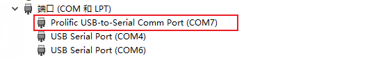
Figure 2-9: Sd_emmc_stress_test-39

Figure 2-10: Sd_emmc_stress_test-40
2.4. Test Results
-
The duration of the test can be determined according to the actual situation.
-
If an abnormality occurs during the stress test, an error log will be output.