Sigmastar eMMC_debugsop Manual
REVISION HISTORY
| Revision No. | Description |
Date |
|---|---|---|
| 1.0 | 02/21/2024 |
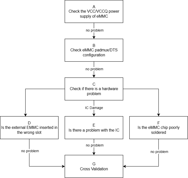
1. Unable to Recognize eMMC Device
| Process | Method | Exit Conditions | Next Step | Information to Provide to FAE | Related FAQs |
|---|---|---|---|---|---|
| A | 1. Use a multimeter to confirm whether the vcc voltage of eMMC during initialization is 3.3v 2. Confirm that the clk-line is low level by default, and cmd/data-line is high level 3. Confirm whether the vccq(IO) voltage of eMMC is within the range of 1.8/3.3v; if EMMC runs in HS200 or HS400 mode, the vccq voltage must be 1.8V |
Exit Condition 1: 1. The vcc power supply of eMMC during initialization is significantly different from 3.3v, 2. or the default state of the bus-line is incorrect, 3. or the vccq power supply of eMMC is not within the effective range of 1.8/3.3v > Power supply issue Exit Condition 2: Power supply is normal> No issue |
Exit Condition 1: > Process ends Exit Condition 2: > B |
Exit Condition 1: ==> Seek hardware assistance |
|
| B | 1. Confirm whether the padmux configuration of eMMC corresponds to the development board, and whether the pad conflicts with other modes. Method: cd vim pcupid_xxxx-padmux.dtsi The eMMC padmux mode will have the keyword 'EMMC8B_BOOT'; the corresponding gpio pad needs to be confirmed for reuse with other modules 2. Confirm whether the dts configuration related to eMMC matches the currently used slot. Method: cd vim pcupid.dtsi For the meaning of related configuration items, please refer to "eMMC Usage Reference", focusing on: 2.1 no-sdio/no-sd/no-mmc; for the type of device connected, comment out the corresponding item and configure the other two, for example: if connecting an eMMC card, comment out no-mmc and configure no-sdio/no-sd |
Exit Condition 1: 1. Padmux is not correctly configured or conflicts with other modes 2. The related configuration items of eMMC in dts do not match the currently used slot > Configuration error issue Exit Condition 2: Configuration is normal> No issue |
Exit Condition 1: > Process ends Exit Condition 2: > C |
Exit Condition 1: ==> Seek hardware FAE to confirm the current padmux situation of the development board, and then configure the correct padmux and dts according to the actual situation |
|
| C | 1. Replace with the same specification eMMC and test whether it can be recognized normally 2. Replace the development board and test whether the same specification eMMC can be recognized normally 3. Test whether the same specification eMMC can be recognized normally on other platforms |
Exit Condition 1: After replacing with the same specification eMMC, it can be recognized normally > eMMC device issue Exit Condition 2: After testing with a different development board, it can be recognized normally > Development board issue Exit Condition 3: After testing on other platforms, it can be recognized normally ==> Driver issue |
Exit Condition 1: > Process ends Exit Condition 2: > Process ends Exit Condition 3: ==> Process ends |
Exit Condition 3: >1. Provide serial log >2. Use LA or oscilloscope to capture the waveform of the entire initialization process ==>3. In the Linux console, use the riu command to dump the relevant bank information of the eMMC IP: 0x1410/0x1038/0x103C/0x103E |
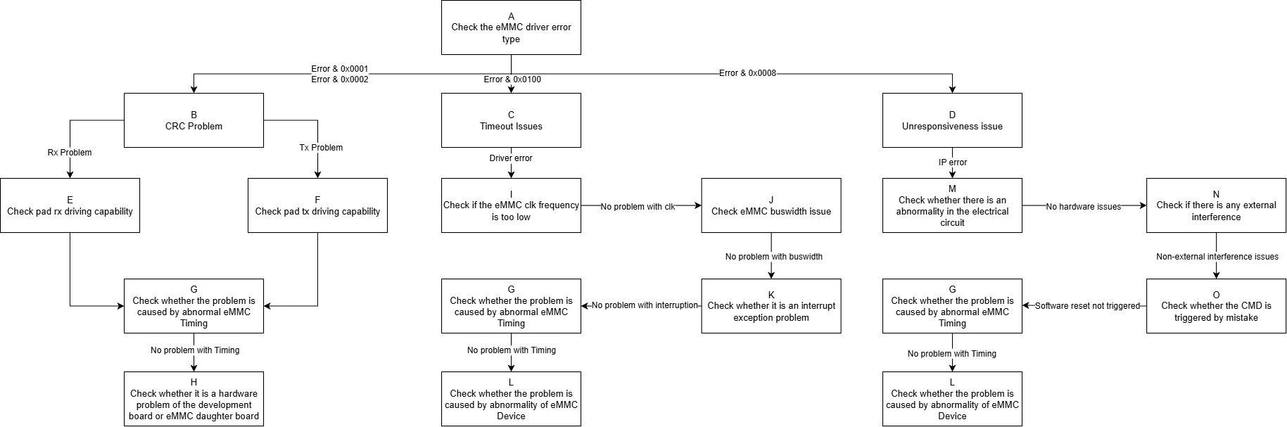
2. eMMC Read/Write Failure Issues
| Process | Method | Exit Conditions | Next Step | Information to be Provided to FAE | Related Reference FAQ |
|---|---|---|---|---|---|
| A | When an error occurs, search the debug log based on the keyword "[sdmmc", mainly focusing on error numbers: 1.(E: 0x0001): Read CRC 2.(E: 0x0002): Write CRC 3.(E: 0x0010): CMD CRC 4.(E: 0x0100): Driver reports Timeout 5.(E: 0x0008): IP reports Device No Response |
Exit Condition 1: 1. Commands 12/13/17/18/23/24/25 and other read/write related commands report CRC errors Exit Condition 2: 1. Commands 12/13/17/18/23/24/25 and other read/write related commands report Timeout errors Exit Condition 3: 1. Commands 12/13/17/18/23/24/25 and other read/write related commands report device not responding errors |
Exit Condition 1: >B Exit Condition 2: >C Exit Condition 3: ==>D |
||
| B | The essence of the CRC issue is poor signal quality, which can be adjusted based on the type of CRC error and combined with adjusting driving (0-7) to select the best driving capability for the pad | Exit Condition 1: 1. The type of CRC error is RX CRC, meaning an error occurred during reading Exit Condition 2: 1. The type of CRC error is TX CRC, meaning an error occurred during writing Exit Condition 3: 1. Other types of CRC errors |
Exit Condition 1: >E Exit Condition 2: >F Exit Condition 3: ==>G |
||
| C | 1. If the driver read/write operation reports a timeout issue, capture the waveform immediately to confirm whether there is a transmission performance issue 2. If there is no issue with the waveform, check whether the eMMC MIE interrupt is reported or received normally, see 3. Check if there are any abnormalities in eMMC Timing, common Timing issues can be found in 4. If none of the above issues exist, consider whether the eMMC Device is abnormal |
Exit Condition 1: 1. The current working frequency is lower than expected based on the waveform Exit Condition 2: 1. The bus width does not match expectations Exit Condition 3: 1. Related events did not trigger normally when errors were displayed in the Debug log Exit Condition 4: 1. eMMC Timing is abnormal Exit Condition 5: 1. eMMC Device causes card busy situation |
Exit Condition 1: >I Exit Condition 2: >J Exit Condition 3: >K Exit Condition 4: >G Exit Condition 5: ==>L |
||
| D | 1. If the eMMC IP reports Device No Response, capture the waveform to confirm whether the CMD was sent without receiving a response 2. Refer to <1: Unable to recognize eMMC device properly>, check whether the relevant configuration is correct 3. Prioritize checking whether the hardware electrical path is normal, and whether the operating environment has undergone interference testing (e.g., electrostatic discharge, high/low temperature, etc.) 4. Search the Debug log for the keyword "SAR1 SDMMC WARN trigger" to determine whether there is an accidental trigger of power-off protection 5. Check if there are any abnormalities in eMMC Timing 6. If none of the above issues exist, consider whether the eMMC Device is abnormal |
Exit Condition 1: 1. Check that the configuration is correct, and the waveform shows that after CMD is sent, no Device response is received Exit Condition 2: 1. Check for significant signal attenuation in the electrical path between the CHIP and the eMMC sub-board Exit Condition 3: 1. The operating environment is currently undergoing electrostatic discharge or high/low temperature stress testing Exit Condition 4: 1. Search the Log and find that eMMC triggered power-off protection without power-off Exit Condition 5: 1. eMMC Timing is abnormal Exit Condition 6: 1. eMMC Device causes no response Exit Condition 7: 1. The waveform shows that the Device has responded, but the IP judges it as unresponsive |
Exit Condition 1: > End of Process Exit Condition 2: 1. Please assist hardware in troubleshooting Exit Condition 3: > End of Process Exit Condition 4: > End of Process Exit Condition 5: >G Exit Condition 6: >L Exit Condition 7: > End of Process |
Exit Condition 1: 1. Dump debug log and DTS configuration file Exit Condition 3: Exit Condition 4: 1. Dump debug log |
|
| E | Adjust driving (0-7) | Exit Condition 1: 1. After setting the data driving level according to the actual situation, it returns to normal Exit Condition 2: 1. After trying all data driving levels, CRC errors still occur |
Exit Condition 1: > End of Process Exit Condition 2: >G |
||
| F | Adjust driving (0-7) | Same as "E" | Same as "E" | ||
| G | 1. Adjust driving (0-7) to comprehensively adjust the driving capability of the CLK/CMD line 2. Adjust the CLK phase 3. Adjust the clock signal sampling mode according to the TMUX table and eMMC REG table 4. When using DMA in trans-mode, set reg_dma_rd_clk_stop to avoid data loss 5. Use LA or an oscilloscope to capture the complete waveform during the problematic phase |
Exit Condition 1: 1. After comprehensively adjusting the driving level of the signal line, it returns to normal Exit Condition 2: 1. After adjusting the CLK's four-phase or eight-phase, it returns to normal Exit Condition 3: 1. After adjusting the clock signal sampling mode, it returns to normal Exit Condition 4: 1. In DMA Mode transmission scenarios, set offset:0xb bit7 to return to normal Exit Condition 5: 1. If the above measures have no effect, the waveform differs from the normal waveform, such as insufficient rise time sampling lock time, cmd overlap, cmd minimum interval not met, etc. Exit Condition 6: 1. Confirm that the above settings are normal, and the waveform has no abnormalities |
Exit Condition 1: Exit Condition 2: Exit Condition 3: Exit Condition 4: > End of Process Exit Condition 5: > End of Process Exit Condition 6: ==>H/L |
Exit Condition 5: 1. Dump the complete debug log of the entire process, including logs from eMMC init to the occurrence of the problem 2. Capture the complete waveform of the abnormal scenario, preferably with a normal scenario waveform under the same conditions for comparison 3. Use the riu command in the Linux console to dump the relevant bank information of the eMMC IP: 0x1410/0x1038/0x103C/0x103E/0x141A |
|
| H | 1. Clarify the version of the eMMC IP used in the current slot according to the manual 1.1 eMMC4.3 supports up to 48MHz 1.2 eMMC5.0 HS200/HS400 supports up to 200MHz 2. Confirm whether it is already at the highest level within the frequency range allowed by the IP 3. Read bank 0x1038 offset 0x43/bank 0x42 offset 0x24 to confirm whether CLK is set successfully as expected |
Exit Condition 1: 1. Adjust CLK to the highest level, communication returns to normal Exit Condition 2: 1. Adjusting CLK has no effect or is already at the highest level Exit Condition 3: 1. CLK setting does not match the register read value |
Exit Condition 1: > End of Process Exit Condition 2: >J Exit Condition 3: ==> End of Process |
Exit Condition 3: 1. Dump 0x1038/0x1133 register information 2. Provide DTS configuration file 3. Provide Debug Log |
|
| I | 1. According to the SPEC document, there are corresponding supported bus widths for different speed modes 1.1 eMMC4.3 can use 1bit/4bit/8bit Buswidth 1.2 eMMC5.0 HS200 can use 4bit/8bit width 1.3 eMMC5.0 HS400 only supports 8bit width 2. Read bank 0x1410 offset 0xb[2:1] to confirm |
Exit Condition 1: 1. Adjust Buswidth to the maximum width corresponding to the speed mode, communication returns to normal Exit Condition 2: 1. Adjusting Buswidth has no effect or is already at the maximum width for that speed mode Exit Condition 3: 1. Buswidth setting does not match the register read value |
Exit Condition 1: > End of Process Exit Condition 2: >K Exit Condition 3: ==> End of Process |
Exit Condition 3: 1. Dump 0x1410 register information 2. Provide DTS configuration file 3. Provide Debug Log |
|
| J | 1. Read bank 0x1410 offset 0x0[1:0] to determine whether the read/write complete event has been raised 2. If the event has been triggered but the driver still reports a timeout, prioritize checking CPU Loading and the number of interrupt triggers |
Exit Condition 1: 1. Within the driver's timeout period, the event has not been raised Exit Condition 2: 1. The event has been raised, and CPU Loading is high or interrupts are triggered frequently Exit Condition 3: 1. The event is raised normally, and there are no other abnormalities in the environment |
Exit Condition 1: > End of Process Exit Condition 2: Investigate which process is causing high CPU Loading, try binding the eMMC MIE interrupt handling to CPU1 Exit Condition 3: >G |
Exit Condition 1: 1. Provide public version reproduction method |
|
| K | 1. First confirm whether the eMMC lifespan has expired: cd /sys/kernel/debug/mmc/mmc:xxxx cat ext_csd The 537~538 bits indicate the life time, refer to SPEC for details 2. Refer to the cross-validation section of <1: Unable to recognize eMMC device properly> 3. Re-solder the eMMC chip |
Exit Condition 1: 1. eMMC life time has exceeded the maximum value or is close to the maximum value Exit Condition 2: 1. After cross-validation or re-soldering, communication returns to normal Exit Condition 3: 1. Confirm that the eMMC device is normal |
Exit Condition 1: > Replace eMMC Exit Condition 2: > End of Process Exit Condition 3: ==> End of Process |
Exit Condition 3: 1. Provide public version reproduction method |
|
| M | 1. Use a multimeter or oscilloscope to test the entire path from the CHIP to the eMMC sub-board, mainly observing whether there is a significant difference in signals near the CHIP end and the eMMC sub-board end | Exit Condition 1: 1. There is a significant attenuation phenomenon in the electrical signal near the CHIP end and the eMMC sub-board end Exit Condition 2: 1. The electrical path is normal |
Exit Condition 1: 1. Please assist hardware in troubleshooting Exit Condition 2: ==>N |
||
| N | 1. Clarify with the customer whether there is external interference in the operating environment, such as ongoing electrostatic discharge, high/low temperature stress testing | Exit Condition 1: 1. Stress testing is ongoing, with additional electrostatic discharge, high/low temperature methods Exit Condition 2: 1. No external interference, normal operating environment |
Exit Condition 1: > End of Process Exit Condition 2: >O |
Exit Condition 1: 1. Capture Debug log and waveform 2. Coordinate with hardware to locate the issue |
|
| O | 1. In a non-power-off operating environment, check whether the Debug log contains the keyword "SAR1 SDMMC WARN trigger" 2. Check whether the filter includes "retry" and "reset" keywords related to the eMMC driver |
Exit Condition 1: 1. Check the Debug log, and there is an eMMC triggering power-off protection or retry operation Exit Condition 2: 1. The environment has not been reset or there is an accidental trigger of eMMC power-off protection |
Exit Condition 1: > End of Process Exit Condition 2: >G |
Exit Condition 1: 1. eMMC accidentally triggered power-off protection 2. If the environment has been triggered to reset, then capture the Debug log |
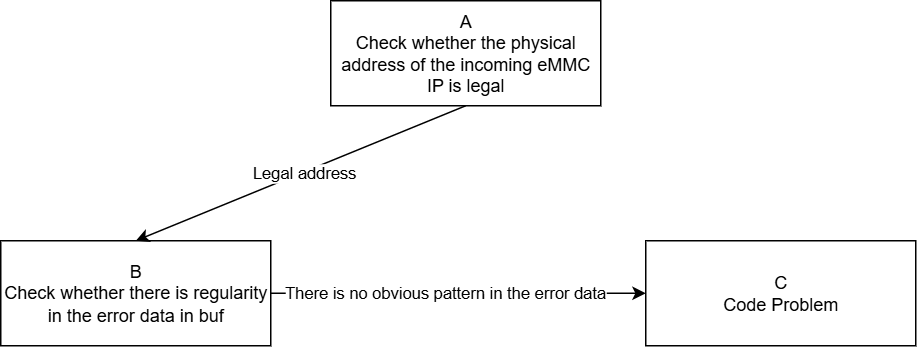
3. eMMC Read/Write Process Successful, But Data in BUF is Problematic
| Process | Method | Exit Conditions | Next Step | Information to be Provided to FAE | Related Reference FAQ |
|---|---|---|---|---|---|
| A | 1. Refer to the specification document to confirm the valid DRAM address space that the eMMC IP can use, and then confirm whether the physical address offset passed to the eMMC IP is valid, i.e., the address composed of bank 1410 offset 0x3/0x4. 2. The available address space in Linux starts from 0x20000000, and the eMMC IP uses the physical address offset reduced by 0x20000000, meaning that offset 0x3/0x4 is the filled physical address, starting from 0 to the maximum available offset, which needs to be confirmed with FAE |
Exit Condition 1: 1. The physical address offset passed to the eMMC IP exceeds the valid range Exit Condition 2: 1. The physical address offset passed to the eMMC IP is valid and effective |
Exit Condition 1: > End of Process Exit Condition 2: >B |
Exit Condition 1: 1. Use the system-provided standard address space allocation interface to request buf |
|
| B | 1. Construct a test pattern, confirm whether there is a regularity in the differences between the source pattern and the read/write obtained pattern, refer to "SD_EMMC Stress Test Reference", and use the fio tool to specify the pattern | Exit Condition 1: 1. The pattern error is obviously regular, always occurring with the eMMC driver Cache-line size error Exit Condition 2: 1. The pattern error has no obvious regularity |
Exit Condition 1: > End of Process Exit Condition 2: >C |
Exit Condition 1: 1. Confirm whether the eMMC standard read/write interface is used; if not, further confirm whether the buf is non-cache 2. Provide public board reproduction environment |
|
| C | The eMMC driver read/write process is normal, but there is an abnormality in the data transfer process within the IP, mainly considering the following points: 1. Is the DMA burst length set to 8, i.e., bank 1410 offset 0x2[5:4] 2. Whether read/write has not considered Cache operations or handled incorrectly 3. Data synchronization issues caused by modern CPU out-of-order execution |
Exit Condition 1: 1. DMA burst length is not set to the maximum Exit Condition 2: 1. In the Cache-on operating environment, the buf read/write did not perform invalid and flush operations, leading to inconsistent data Exit Condition 3: 1. Logic requiring synchronization calls did not perform memory barrier processing, causing out-of-order execution Exit Condition 4: 1. Other issues |
Exit Condition 1: 1. Try manually setting the DMA burst to the maximum value of 8 Exit Condition 2: 1. Try performing flush operations during write operations and invalid operations after read operations Exit Condition 3: Exit Condition 4: ==> End of Process |
Exit Condition 3: Exit Condition 4: 1. Confirm the current status of the customer branch and patches applied 2. Provide public board reproduction environment |
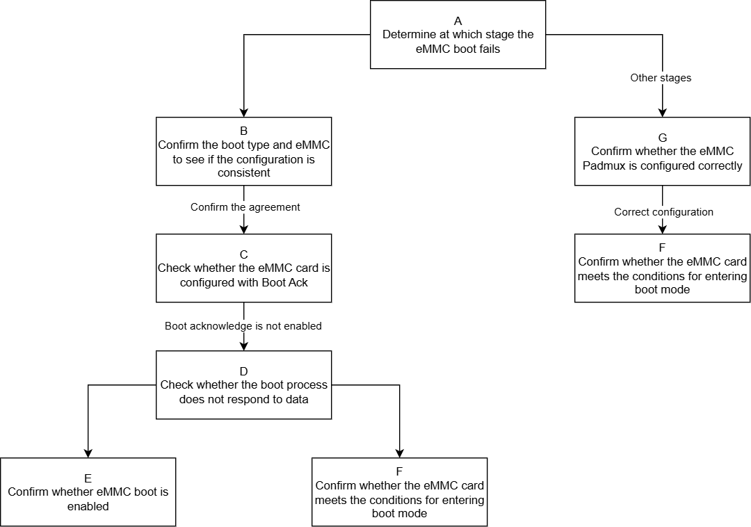
4. eMMC Boot Issues
| Process | Method | Exit Conditions | Next Step | Information to be Provided to FAE | Related Reference FAQ |
|---|---|---|---|---|---|
| A | First, retrieve the Debug Log to determine at which stage the eMMC Boot failed. 1. If it fails at the ROM stage, the Log will not show keywords for IPL and subsequent stages. 2. If it fails after the ROM stage, you can determine which stage of IPL/IPL_CUST/UBOOT it is based on the last keyword that appeared, and then analyze the problem specifically. |
Exit Condition 1: 1. eMMC Boot fails at the ROM stage. Exit Condition 2: 1. eMMC Boot fails after the ROM stage. |
Exit Condition 1: >B Exit Condition 2: >G |
||
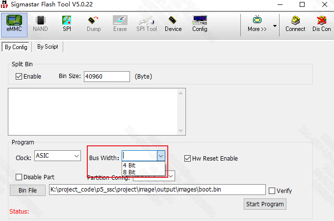
| B | If it fails at the ROM startup stage, first check whether the boot strap on the development board matches the selection made during isptool programming. The latest version of isptool can automatically match; for older versions, pay attention to ensure that the 'Bus Width' option on the selection board matches the boot strap selection on the development board. | Exit Condition 1: 1. The Bus width selected during isptool programming does not match the boot strap type. Exit Condition 2: 1. Both configurations match. |
Exit Condition 1: Correct the Bus width during isptool programming. Exit Condition 2: ==>C |
||
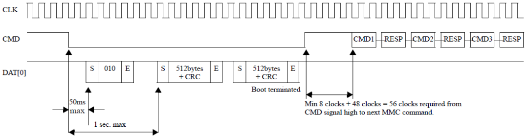
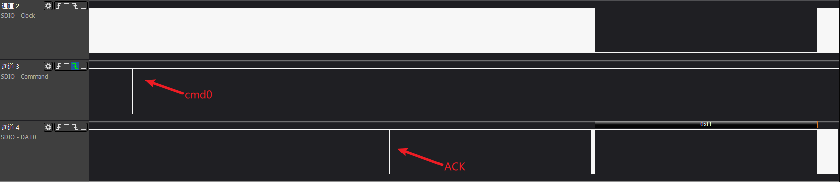
| C | According to the SPEC, the Boot Ack mechanism will reply with Ack information on the Dat0 line within a maximum of 50ms after cmd0 is issued. Capture the waveform to confirm whether the Boot Ack mechanism is enabled or if there are violations of SPEC regulations. Generally, this can be determined by the first parameter of the uboot programming command 'mmc partconf', where 0 means disable Ack; 1 means enable Ack. | Exit Condition 1: 1. The Boot ACK mechanism is enabled, and Ack information appears on other data lines. Exit Condition 2: 1. Boot Ack is not configured to be enabled. |
Exit Condition 1: Disable the Boot Ack mechanism, i.e., set ExtCSD[179]bit6 to 0. Exit Condition 2: ==>D |
||
| D | Capture the eMMC Boot waveform to confirm whether there is a response to the Boot partition data. | Exit Condition 1: 1. No response to Boot partition data after cmd0 is sent; querying ECSD[179]bit[5:3] shows that the card has not enabled Boot mode. Exit Condition 2: 1. No response to Boot partition data after cmd0 is sent, and the waveform indicates that the conditions for entering Boot mode are not met. |
Exit Condition 1: >E Exit Condition 2: >F |
||
| E | Read the ECSD[179]bit[5:3] register and analyze whether the eMMC card has enabled Boot mode according to the SPEC. | Exit Condition 1: 1. The eMMC card has not enabled Boot mode. Exit Condition 2: 1. The eMMC card has enabled Boot mode. |
Exit Condition 1: 1. Use isptool to reprogram and do not check disable part. Exit Condition 2: ==>F |
||
| F | According to the SPEC, the eMMC card Boot mode includes three states: 1. pre-idle state, which can be entered in three ways: 1.1 after power on; 1.2 cmd0(arg:0xf0f0f0f0) command 1.3 hw reset by host 2. pre-boot state: after power on or reset and before sending the first command cmd1, the cmd line must remain low for at least 74 clock cycles. 3. boot state: perform Boot partition data reading, mainly through: 3.1 cmd line low level 3.2 cmd0(arg:0xfffffffa), the current method used by eMMC |
Exit Condition 1: 1. Failed to enter pre-idle state, meaning the current eMMC's HW reset or cmd0(arg:0xf0f0f0f0) is ineffective for the eMMC card. Exit Condition 2: 1. eMMC Timing has issues. |
Exit Condition 1: 1. Try switching between HW reset/SW reset methods to resolve. Exit Condition 2: ==>Process End |
Exit Condition 2: 1. Capture eMMC Boot waveform and Dump log. 2. Provide public board reproduction environment. |
|
| G | Check whether the eMMC Padmux configuration is correct. | Exit Condition 1: 1. There is an issue with the eMMC Padmux configuration. Exit Condition 2: 1. The eMMC Padmux configuration is correct. |
Exit Condition 1: 1. Configure correctly based on the actual operating environment. Exit Condition 2: ==>F |
5. Appendix
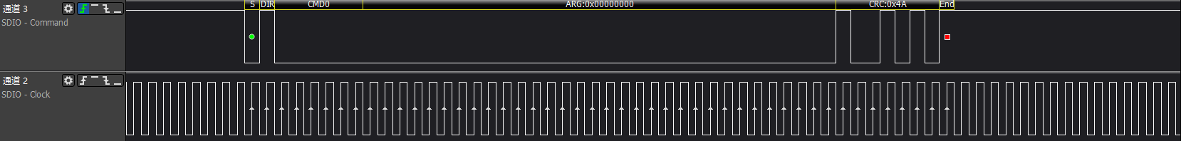
5.1 eMMC Device High Speed Mode Initialization Process
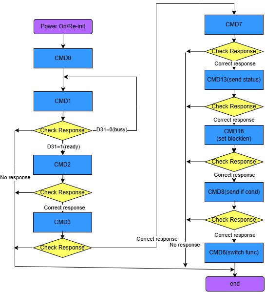
>>>emmc go idle: cmd0 makes the card enter idle state
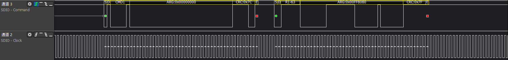
>>>Get OCR register information: Retrieve the card's OCR information and wait for the card to be ready
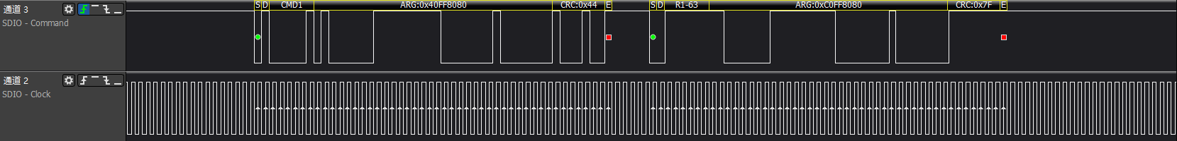
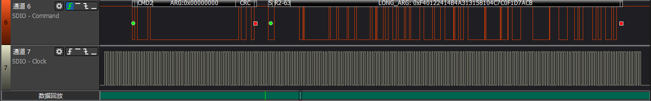
>>>Get CID register information
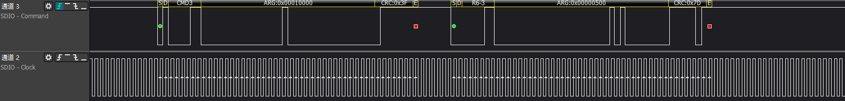
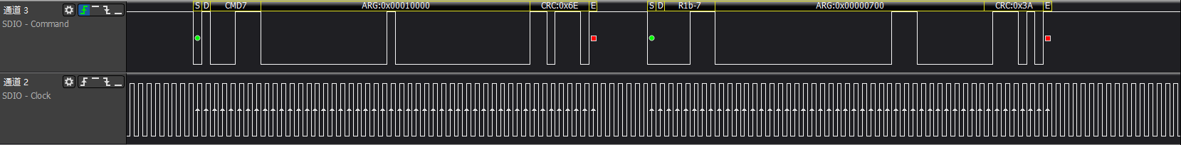
>>>cmd3/cmd7: Host retrieves eMMC card RCA address and puts the card into trans-state
>>>Set EMMC block length
>>>Get EXT-CSD register information: Important extended register information for eMMC
>>>cmd6+cmd13 switch operation: Perform a series of settings and enable functions
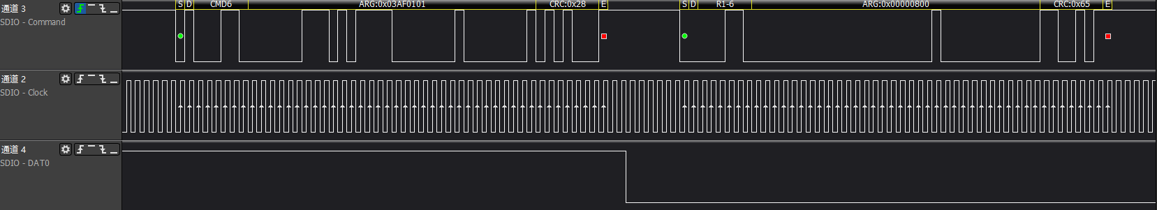
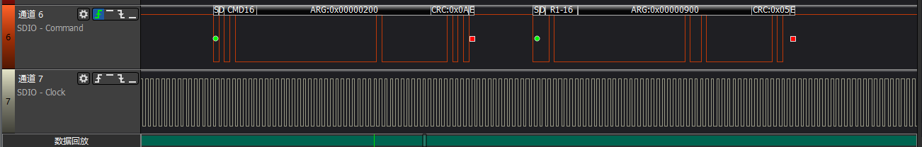
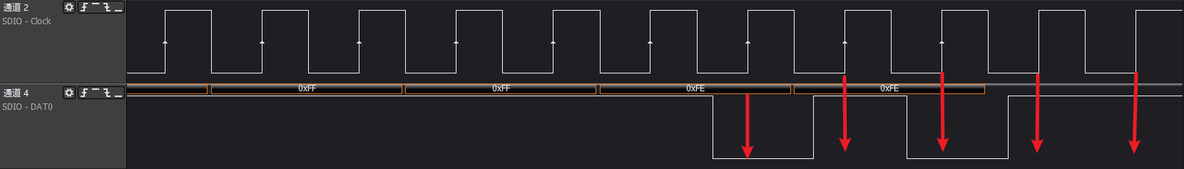
Sometimes it may also be paired with asserting a busy signal (data0 pulled low) + r1 response to cmd6, as shown in the figure. The switch operations mainly include the following:
1. Enable erase group
2. ext-csd[179] boot partition enable
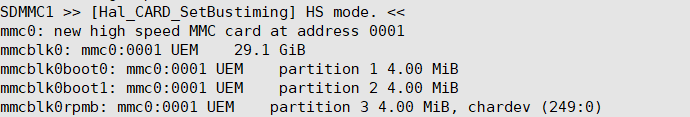
3. Switch to high-speed; after this step, the clock is 48MHz.
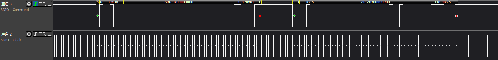
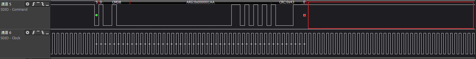
4. Switch bus width and confirm by sending cmd8.
5. Select power class to confirm power supply voltage.
6. Switch cache control to enable cache functionality.
After completing these steps, because the card device is generated, it will match with the card driver to generate a block device node.
>>>eMMC card identification successful
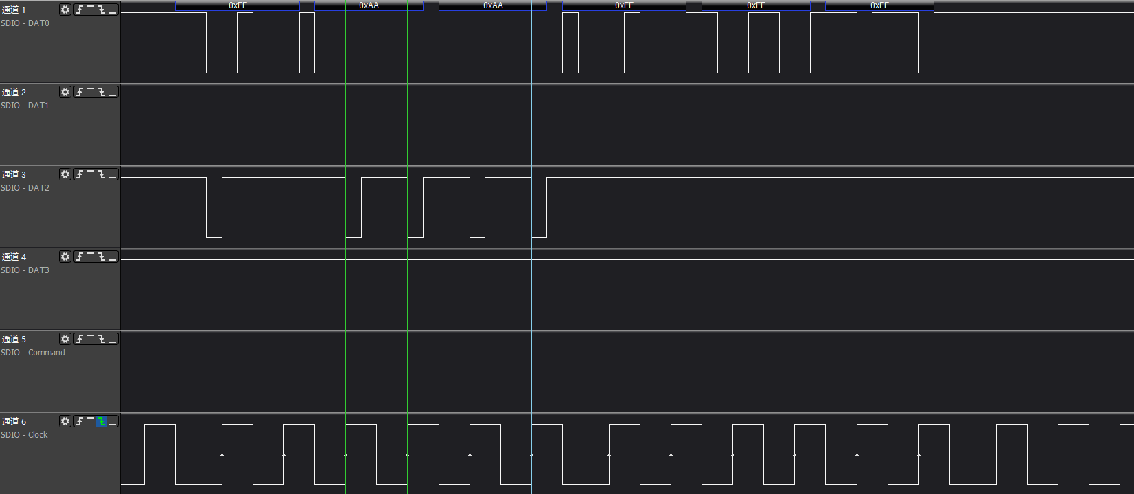
5.2 Common eMMC Error Waveforms and Logs
>>>cmd no rsp

The driver will print SD_STS:0x0F08 error code.
>>>cmd crc


The CRC for read commands is an internal check by the IP.
The driver will print SD_STS:0x0F01 (read CRC)/SD_STS:0x0F02 (write CRC) error codes.
>>>cmd timeout
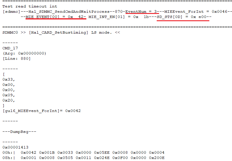

The driver will print (FAIL)= 0100 error code, indicating that the waiting time set by the driver has been reached, but the event has not been received.
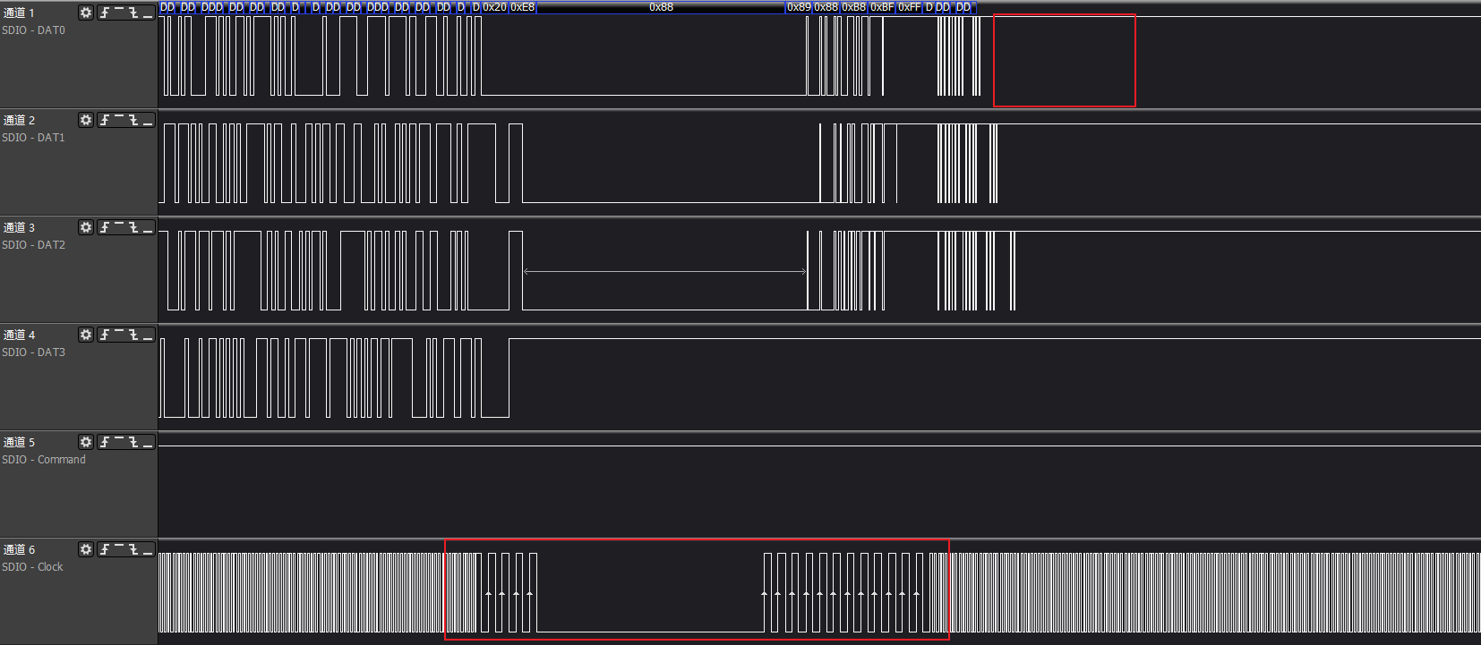
Here, you can focus on the key information printed by the driver, 'eventnum=3' indicates that it is waiting for a read cmd with data, 'MIE_EVENT[00]=0x42' indicates that only the cmd response was received, but the dat_end event was not received.
Additionally, you can pay attention to 'SD_STS[0D]=0xe00', which is the high 8 bits of the sd status register. If it is not all 1s, it indicates that there is a low condition on the data line, which generally means that data is still being transmitted or has been pulled low.
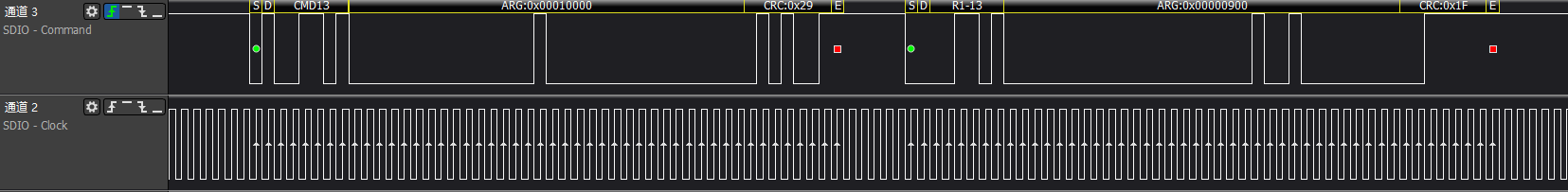
>>>cmd6 execution switch func error
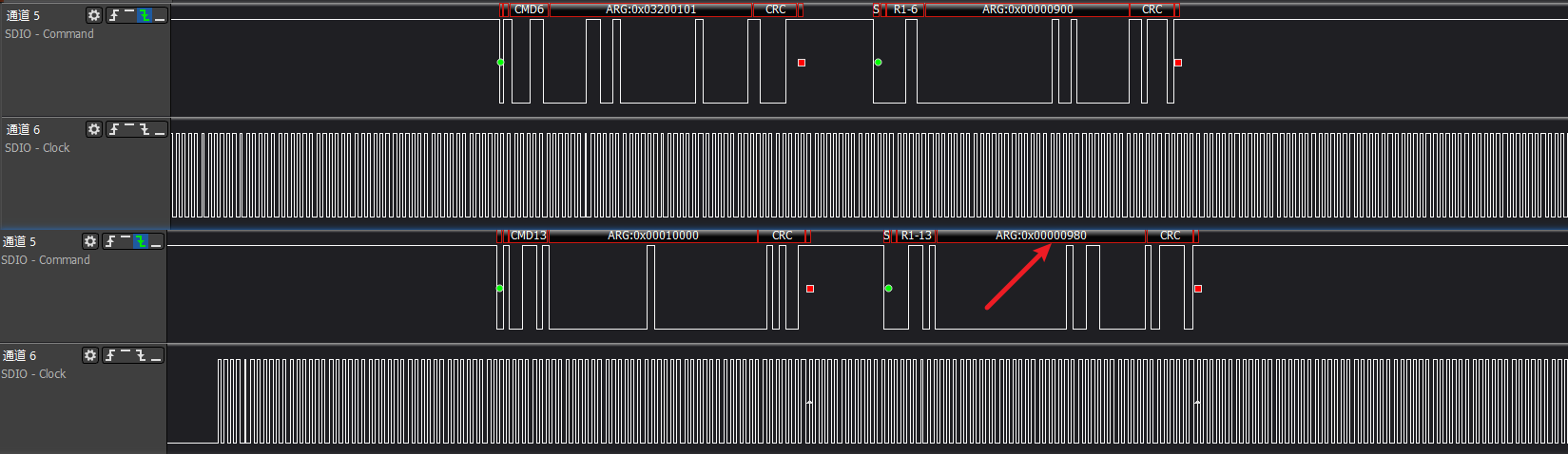
The figure shows a switch error, with the cmd13 response status displaying '980', indicating a device switch error.
>>>eMMC boot

>>>eMMC isptool
>>>eMMC boot ack
>>>Common timing issue 1: clk is turned off when cmd is issued
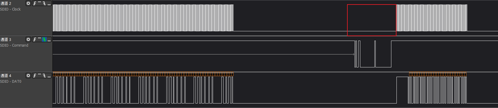
>>>Common timing issue 2: clk is abnormal when cmd is issued, causing cmd to not be recognized properly
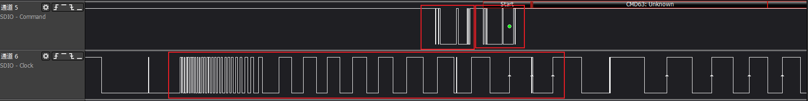
>>>Common timing issue 3: External interference such as static electricity/high and low temperatures causes clk anomalies
>>>Common timing issue 4: clk has almost no sampling setup time, easily leading to misjudgment