Sensor Click Program Description
1. Introduction to Sensor Image Display Functionality
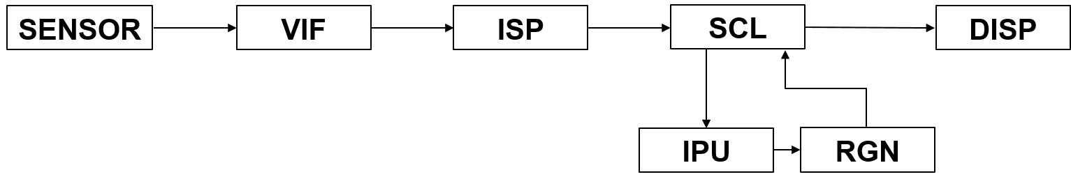
This demo primarily demonstrates how to connect the entire pipeline from Sensor to Panel, as shown in the diagram above. It uses the IPU to perform target detection and display the results in real-time within the pipeline, specifically supporting the following functionalities:
-
Functional Scene: The video collected by the sensor is displayed on the panel (the terms sensorTopanel and sensor2panel mentioned elsewhere in the text refer to this functionality)
-
Video Stream: sensor->vif->isp->scl->(vdisp)->disp->panel
-
Supports dual-camera configuration
-
Supports dynamic switching of vif-isp binding methods
-
Supports configuration of iqbin path
-
Supports iq tool debugging
-
Supports configuration of TTL and MIPI screens
-
Supports output of one RGB and one IR display
-
Supports single-channel object detection bounding boxes
-
Supports configuration of the iqbin path
2. Compilation Environment Description
Note
Generally, the corresponding programs have already been packaged on the board by default, so program compilation is not mandatory. You can directly find prog_disp_sensor2Panel_demo in the /customer/sample_code/disp_sensor2Panel_demo folder on the board. If you cannot find the file or have a need to modify the program, you can refer to the following steps.
-
dts configuration
-
Configure screen dts
Taking the MIPI screen as an example, you need to modify the corresponding
// MIPIDSI 4 LANEpart inkernel/arch/arm/boot/dts/pcupid-comake-pi-d1-dual-sensor-padmux.dtsitoif 1, so that the device tree for MIPIDSI 4lane is opened for compilation. -
Configure sensor dts
If using gc2053, 1-lane sensor + 1-lane sensor, modify the following section in
kernel/arch/arm/boot/dts/pcupid-comake-pi-d1-dual-sensor.dtscsi: csi { ... /* Config max lane number, sr0 set to 2 include 1lan support*/ csi_sr0_lane_num = <2>; csi_sr2_lane_num = <1>; /* Config lane selection */ csi_sr0_lane_select = <0 1 2>; csi_sr2_lane_select = <0 1>; /* Config lane P/N swap */ csi_sr0_lane_pn_swap = <0 0 0>; csi_sr2_lane_pn_swap = <0 0>; }; sensorif: sensorif { compatible = "sstar,sensorif"; status = "okay"; clocks = <&CLK_sr00_mclk>, <&CLK_sr01_mclk>; /* Config sensor 0 pad mux */ snr_sr0_mipi_mode = <5>; snr_sr0_mipi_mclk_mode = <2>; snr_sr0_rst_gpio = <73>; snr_sr0_pdn_gpio = <77>; snr_sr0_par_mode = <2>; snr_sr0_par_rst_mode = <2>; snr_sr0_par_pdn_mode = <1>; snr_sr0_par_mclk_mode = <2>; ... /* Config sensor 2 pad mux */ snr_sr2_mipi_mode = <5>; snr_sr2_rst_gpio = <77>; snr_sr2_mipi_pdn_mode = <0>; snr_sr2_mipi_mclk_mode = <2>; ... };
For further sensor driver configuration, please refer to SENSOR USEER GUIDE
-
-
In the project path, select defconfig for the board (nand/nor, ddr model, etc.) to perform a full package compilation.
For example, for Comake PI D1 model board using emmc and ddr4 configuration, use the following defconfig; for other board models, refer to the user manual:
dispcam_pcupid.emmc.glibc-12.4.0-arm-squashfs.comake.pi.d1.1024.dual_sensor.bga_ddr4_riscv_defconfigExecute the following commands in the project directory for compilation:
make dispcam_pcupid.emmc.glibc-12.4.0-arm-squashfs.comake.pi.d1.1024.dual_sensor.bga_ddr4_riscv_defconfigmake clean && make image -j8 -
Navigate to the sdk/verify/sample_code directory and execute
make clean && make source/pcupid/disp/sensor2Panel_demofor compilation; -
Go to
sdk/verify/sample_code/out/arm/app/prog_disp_sensor2Panel_demoto get the executable file; -
Place the executable file prog_disp_sensor2Panel_demo on the board at the path /customer/sample_code/disp_sensor2Panel_demo and change the permissions to 777.
3. Runtime Environment Description
-
Board Environment
Connecting MIPI screen and touchscreen: Insert the touchscreen and MIPI screen FPC cables into the CON9 and CON8 interfaces on the board.
Connecting Sensor: Connect the (single/dual) gc2053 sensor at J5 /J6.
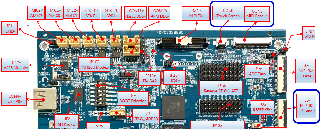
CON8 MIPI screen is connected from above with FPC; ensure not to connect it the wrong way, as shown in the first image below.
For CON9, the FPC is connected from below near the screen side, and from above near the mainboard side; ensure not to connect it incorrectly, as illustrated in the second image below.
J5 sensor is connected from below with FPC; ensure not to connect it the wrong way, as shown in the images on the right below.

-
Sensor Driver Configuration
Note
If you are using the code package we provided and have compiled with the defconfig from the example, then the following dts configurations do not need to be modified as they are already configured by default.
Modify the insmod path in /customer/demo.sh to match the corresponding sensor ko, for example, when running a single sensor with gc2053, you can set it as:
insmod /config/modules/6.1/gc2053_mipi.ko chmap=1
For dual sensors, configure it as:
insmod /config/modules/6.1/gc2053_mipi.ko chmap=5
4. Execution Instructions
Execute cd /customer/sample_code/disp_sensor2Panel_demo to navigate to the corresponding file path.
Parameter explanation as follows:
-b
Select the vif-isp binding method
0: vif isp real-time binding (single camera defaults to real-time; dual camera can only use frame mode)
1: vif isp frame mode binding
-n
Initialize sensor pad selection
0: initialize sensor pad0 (default 0)
1: initialize sensor pad2
2: initialize sensor pad0 and sensor pad2
-p
Select the type of screen to use
0: TTL screen (default TTL screen)
1: MIPI screen
-i
Directory to store iqbin, for example, -i /customer means the iqbin for sensor0 is at /customer/iqApiBin0.bin, and for sensor1 at /customer/iqApiBin1.bin
-c
Choose sensor index, starting from 0. Default value is 0. Different indices of gc2053 correspond to different lane configurations.
-t
Select display output timing; currently, only the following options are available, and you can add others if different screens are used.
0: E_MI_DISP_OUTPUT_USER (used for TTL)
1: E_MI_DISP_OUTPUT_720P60
2: E_MI_DISP_OUTPUT_1080P60
-w
Enable isp output for the IR image, requires dual cameras.
0: disable
1: enable
-d
Enable object detection, only supports single camera.
0: disable
1: enable
-m
Load the object detection model path, default path: /customer/yolov8n_800x480_P3P_fixed.sim_sgsimg.img
Execution Examples
1. Run sensor pad0 individually, MIPI 720p screen

./prog_disp_sensor2Panel_demo -b 0 -n 0 -c 1 -p 1 -t 0 -r 90 -i "/customer"

2. Run sensor pad2 individually, MIPI 720p screen

./prog_disp_sensor2Panel_demo -b 0 -n 1 -c 1 -p 1 -t 0 -r 90 -i "/customer"

3. Simultaneously run pad0 and pad2, MIPI 720p top-and-bottom split screen

./prog_disp_sensor2Panel_demo -b 0 -n 2 -c 1 -p 1 -t 0 -r 90 -i "/customer"

4. Simultaneously run pad0 and pad2, MIPI 720p rotate 90 split screen display

./prog_disp_sensor2Panel_demo -n 2 -c 1 -p 1 -t 0 -r 90 -w 1 -i "/customer"

5. Single sensor object detection, MIPI 720p rotate 90 display

./prog_disp_sensor2Panel_demo -p 1 -t 0 -n 0 -r 90 -c 1 -d 1 -m /customer/sample_code/disp_sensor2Panel_demo/model/yolov8n_800x480_P3P_fixed.sim_sgsimg.im -i "/customer"
During execution, follow the serial port prompts:
select 0: change vif->isp bind mode (this option only supports single sensor scenarios, as dual sensors can only use real-time mode)
select 110: quit app
Enter the corresponding number to select different bind modes.
5. Execution Result Description
-
Effect Viewing
Function 1: Connect the sensor for testing pad0's individual display.
Execute the command
./prog_disp_sensor2Panel_demo -c 1 -n 0 -p 1 -t 0 -r 90, and the display shows the following image, indicating that the screen is displaying the image captured by sensor0 normally.
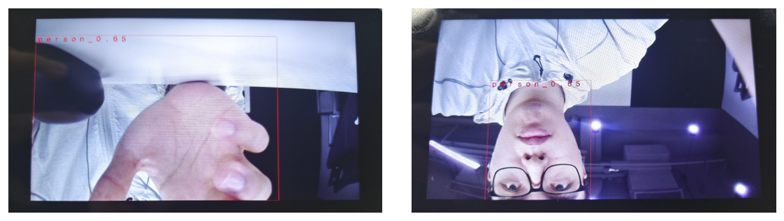
Function 2: Human shape recognition
Execute the command
./prog_disp_sensor2Panel_demo -p 1 -n 0 -c 1 -r 90 -d 1 -m model/yolov8n_800×480_P3P_fixed.sim_sgsimg.img, and the display shows the following image with hands and faces moving in front of the camera.The screen image displays the output from the sensor normally, allowing the drawing of recognition boxes, with person_0.xx printed.
-
Exit Command
Enter
110to quit the demo, it will exit the sensor0's captured image, displaying black.