IR USER GUIDE
REVISION HISTORY
| Revision No. | Description | Date |
|---|---|---|
| 1.0 | 04/18/2023 | |
| 1.1 | 04/08/2025 |
1. OVERVIEW
Infrared Receiver (IR) is mainly used to analyze the signal sent by the infrared remote control, which is a series of binary pulse codes. In order to prevent the infrared signal from being interfered by other signals during wireless transmission, it is usually modulated at a specific carrier frequency (38KHZ) and then transmitted through the infrared transmitting diode. The IR receives the signal of the specific frequency after filtering out other clutter and restores it to a binary pulse code, that is, demodulation. The decoding methods supported by SigmaStar IR are Full, Raw, SW and RC, and the protocols supported are NEC, RC5 and RC6.
2. Keyword
None.
3. FUNCTION DESCRIPTION
3.1. Basic Function
-
Support 5 groups of IR hardware.
-
Pulse signals less than 170us will be filtered.
-
The default clock frequency is 12MHZ, and the clock adjustment is not supported.
-
Supported decoding modes are Full, Raw, SW and RC5 (note that RC6 software is not supported yet), for configuration details, see IR DTS Configuration Description.
3.2. IR Decoding Method
SigmaStar's IR_IN signal can be decoded in four decoding modes: Full mode, Raw mode, SW mode, and RC mode.
When the IR_IN signal is in NEC/NEC-like format, Full/Raw/SW mode can be used for decoding.
When the IR_IN signal is in RC format, it can be decoded in RC/SW mode (currently the driver only supports RC5 format).
When the IR_IN signal is in other format, it can only be decoded in SW mode (it needs to be used with a decoder).
-
Full mode
The hardware can decode IR_IN signals in NEC/NEC-like format and identify user codes and key codes.
-
Raw mode
The hardware can decode IR_IN signals in NEC/NEC-like format, but cannot identify which part is the user code or key code, which needs to be determined by software.
-
SW mode
The hardware cannot identify any format from the IR_IN signal, and software is required to decode the signal format, user code and key code.
-
RC mode
The hardware can decode IR_IN signals in RC format and identify user codes and key codes.
As can be seen from the block diagram below, there are two main paths for infrared decoding. The upper path is Full/Raw/SW mode, and the lower path is RC mode.

3.3. Each Protocol Level Standard
NEC format:
-
Logic0: 0.56ms high + 0.56ms low
-
Logic1: 0.56ms high + 1.68ms low
-
Header code: 9ms high pulse
-
Off code: 4.5ms low pulse:
-
Customer code: 8-bits customer code + 8-bits inverse or 16-bits customer code
-
Command code: 8-bits command code + 8-bits inverse
-
Total cycle time: 108ms
-
Repeat key: 9ms Header code and 2.5ms Off code

Figure 2-2: NEC Format Standard
NEC-like format:
-
Logic0: short high + short low (usually 1:1)
-
Logic1: short high + long low (usually 1:3)
-
Header code: ultra long high width
-
Off code: ultra long low width
RC5 format:
-
Logic0: 888us high + 888us low (Manchester code)
-
Logic1: 888us low + 888us high (Manchester code)
-
Start bits: 2-bits logic1
-
Toggle bit: Inverted every time when the key is released and pressed again
-
Customer code: 5-bits customer code
-
Command code: 6-bits command code
-
Total cycle time: 114ms
-
If a key is held over 114ms, it will repeat the signal every cycle time

Figure 2-3: RC5 Format Standard
RC5-Extend format:
-
Same as RC5 expect the second bit of SB is represented the 6th bit of address code

Figure 2-4: RC5-Extend Format Standard
RC6 mode 0 format:
-
Logic0: 444us low + 444us high (Manchester code)
-
Logic1: 444us high + 444us low (Manchester code)
(Note the logic length is half of RC5 format and the level order is opposite)
-
Header code: 2.666ms high pulse + 888us low pulse
-
Start bit: 1-bit logic1
-
Mode bits: 3-bit logic0 (in mode 0)
-
Toggle bit: Inverted every time when the key is released and pressed again
-
Customer code: 8-bits customer code
-
Command code: 8-bits key code
-
If a key is held over 114ms, it will repeat the signal every cycle time.

Figure 2-5: RC6 Mode 0 Format Standard
4. HARDWARE CONNECTION INTRODUCTION
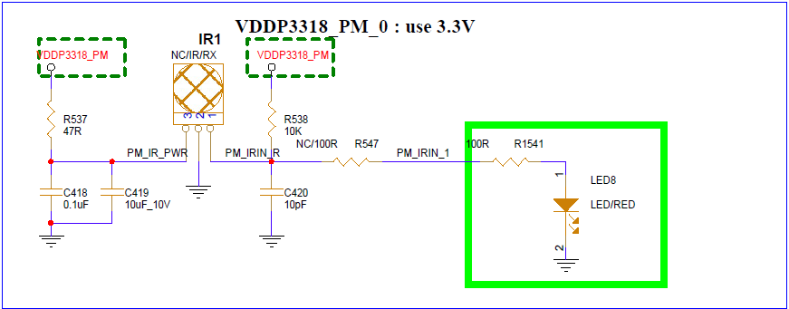
Connect the infrared receiver to the development board according to the direction indicated in the schematic.
5. Uboot USAGE INTRODUCTION
Not Support.
6. KERNEL USAGE INTRODUCTION
Driver path: kernel/drivers/sstar/ir
6.1. Configure Kennel Config
The configurations that need to be selected when compiling the kernel are as follows:
If you do not use SW mode, you only need to configure the following two configs:
Device Driver->

    <*> SStar SoC platform drivers->

        <*> Sstar IR driver

Device Driver->

    Input device support->

        <*> Generic input layer(needed for keyboard, mouse... .)
If you use SW mode, you need to use it with a decoder. You can choose Kernel's decoder. Take the NEC protocol as an example:
Device Driver->

    <*> Remote Controller support->

        <*> Remote Controller decoders->

            <*> Enable IR raw decoder for the NEC protocol
6.2. Configure DTS
The DTS configuration of IR only needs to configure the following information in the corresponding chipname.dtsi:
ir4: ir@1F007A00 {
    compatible = "sstar,ir";
    reg = <0x1F007A00 0x200>;
    clocks = <&CLK_ir>;
    interrupts = <GIC_SPI INT_FIQ_IR IRQ_TYPE_LEVEL_HIGH>,<GIC_SPI INT_FIQ_IR_RC IRQ_TYPE_LEVEL_HIGH>;
    group = <4>;
    /*
     * decode mode selection
     * FULL   1  Format: NEC/NECX
     * RAW    2  Format: NEC/NECX
     * RC5    3  Format: RC5
     * SW     4  Format: /
     */
    mode = <2>;
    //choose enum rc_proto for sw mode
    protocol = <9>;
    vendor = <0x000E>;
    product = <0x3412>;
    //rc-map-table = <customer_code + command_code  input_key_code>
    rc-map-table =
        //NEC Remote Control NO.1
        <0x00FFA8 KEY_POWER>,          <0x00FFC0 KEY_F5>,            <0x00FFDD KEY_GREEN>,
        <0x00FF44 KEY_F19>,            <0x00FFCA KEY_UP>,            <0x00FFD2 KEY_DOWN>,
        <0x00FF99 KEY_LEFT>,           <0x00FFC1 KEY_RIGHT>,         <0x00FFCE KEY_ENTER>,
        <0x00FFCB KEY_BACK>,           <0x00FF87 KEY_HOMEPAGE>,      <0x00FF97 KEY_COMPOSE>,
        <0x00FF41 KEY_PLAYPAUSE>,      <0x00FF0F KEY_F16>,           <0x00FF60 KEY_F20>,
        <0x00FF90 KEY_VOLUMEUP>,       <0x00FF98 KEY_VOLUMEDOWN>,    <0x00FFD1 KEY_MUTE>,
        //NEC Remote Control NO.2
        <0x807F46  KEY_POWER>,          <0x807F50  KEY_0>,           <0x807F49  KEY_1>,
        <0x807F55  KEY_2>,              <0x807F59  KEY_3>,           <0x807F4D  KEY_4>,
        <0x807F51  KEY_5>,              <0x807F5D  KEY_6>,           <0x807F48  KEY_7>,
        <0x807F54  KEY_8>,              <0x807F58  KEY_9>,           <0x807F47  KEY_RED>,
        <0x807F4B  KEY_GREEN>,          <0x807F57  KEY_YELLOW>,      <0x807F5B  KEY_BLUE>,
        <0x807F52  KEY_UP>,             <0x807F13  KEY_DOWN>,        <0x807F06  KEY_LEFT>,
        <0x807F1A  KEY_RIGHT>,          <0x807F0F  KEY_ENTER>,       <0x807F1F  KEY_CHANNELUP>,
        <0x807F19  KEY_CHANNELDOWN>,    <0x807F16  KEY_VOLUMEUP>,    <0x807F15  KEY_VOLUMEDOWN>,
        <0x807F03  KEY_PAGEUP>,         <0x807F05  KEY_PAGEDOWN>,    <0x807F17  KEY_HOME>,
        <0x807F07  KEY_MENU>,           <0x807F1B  KEY_BACK>,        <0x807F5A  KEY_MUTE>,
        <0x807F0D  KEY_RECORD>,         <0x807F42  KEY_HELP>,        <0x807F14  KEY_INFO>,
        <0x807F40  KEY_KP0>,            <0x807F04  KEY_KP1>,         <0x807F0E  KEY_REWIND>,
        <0x807F12  KEY_FORWARD>,        <0x807F4C  KEY_ZOOM>,        <0x807F02  KEY_PREVIOUSSONG>,
        <0x807F1E  KEY_NEXTSONG>,       <0x807F01  KEY_PLAY>,        <0x807F1D  KEY_PAUSE>,
        <0x807F11  KEY_STOP>,           <0x807F44  KEY_AUDIO>,       <0x807F56  KEY_CAMERA>,
        <0x807F5C  KEY_CHANNEL>,        <0x807F45  KEY_SLEEP>,       <0x807F4A  KEY_EPG>,
        <0x807F10  KEY_LIST>,           <0x807F53  KEY_SUBTITLE>,    <0x807F41  KEY_FN_F1>,
        <0x807F4E  KEY_FN_F2>,          <0x807F0A  KEY_FN_F3>,       <0x807F09  KEY_FN_F4>,
        <0x807F1C  KEY_FN_F5>,          <0x807F08  KEY_FN_F6>,       <0x807F0B  KEY_F1>,
        <0x807F18  KEY_F2>,             <0x807F00  KEY_F3>,          <0x807F0C  KEY_F4>,
        <0x807F4F  KEY_F5>,             <0x807F5E  KEY_F6>,          <0x807F43  KEY_F7>,
        <0x807F5F  KEY_F8>,             <0x807FFE  KEY_POWER2>,      <0x807FFF  KEY_OK>,
        //RC5 Remote Control
        <0x150C  KEY_POWER>,          <0x153F  KEY_AUX>,         <0x141D  KEY_MEDIA_REPEAT>,
        <0x141C  KEY_SHUFFLE>,        <0x100D  KEY_MUTE>,        <0x104F  KEY_F4>,
        <0x143F  KEY_F1>,             <0x112D  KEY_F2>,          <0x112E  KEY_F3>,
        <0x1010  KEY_VOLUMEUP>,       <0x1011  KEY_VOLUMEDOWN>,  <0x1521  KEY_PREVIOUSSONG>,
        <0x1520  KEY_NEXTSONG>,       <0x1536  KEY_PAUSE>,       <0x1535  KEY_PLAY>,
        <0x151F  KEY_BACK>,           <0x151E  KEY_FORWARD>,     <0x1063  KEY_MAX>,
        <0x1040  KEY_F6>,             <0x1120  KEY_CHANNELUP>,   <0x1121  KEY_CHANNELDOWN>;
    status = "ok";
};
IR DTS Configuration Description:
| Attribute | Description | Setting Value | Remark |
|---|---|---|---|
| compatible | Match the driver for driver registration | "sstar,ir" | Modification prohibited |
| reg | Set the register bank address | <0x1F007A00 0x200> | Modification prohibited |
| interrupts | Set the interrupt number and attributes | INT_FIQ_IR , INT_FIQ_IR_RC | Modification prohibited |
| clocks | Set the clock source | <&CLK_ir> | No modification required |
| group | Set IR hardware serial number | 0 | No modification required |
| mode | Set the decoding mode at initialization | ½/¾ corresponds to FULL/RAW/RC5/SW | Can be modified as needed |
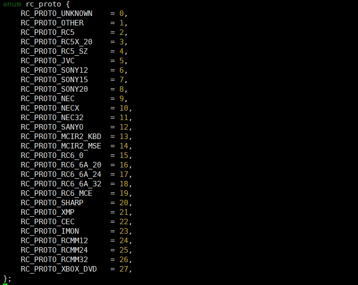
| protocol | Match the decoder protocol in SW mode | See Figure 5-5: rc_proto Option | Can be modified as needed |
| vendor | Set the input id attribute of RC device | 0x0000~0XFFFF, which can be used to distinguish the remote control | Can be changed according to the remote control settings |
| product | Set the product attribute of RC device | 0x0000~0XFFFF, which can be used to distinguish the remote control | Can be changed according to the remote control settings |
| rc-map-table | The code values sent by the remote control and the corresponding Input event codes | 0x00FFA8: The upper 16 bits are the user code, and the lower 8 bits are the key code; KEY_POWER: Input event codes | Can set the map table for different remote controls |
| status | Select whether to enable IR driver | "ok" or "disable" | Can be modified as needed |
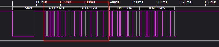
Combined with Figure 5-4, the following explains how to fill in the rc-map-table:
ADDR + IADDR: 0x807F, that is, the user code is 0x807F;
CMD: 0x4A, that is, the key code is 0x4A;
Therefore, the value filled in the left column of the rc-map-table key-value pair is 0x807F4A, and the right column is filled with a certain Input event codes that you want to report.
If you use SW mode, make menuconfig to configure the kernel native decoder or write your own decoder, you need to modify the following configuration in DTS:
If the user code of the attribute "rc-map-table" is the upper 8 bits and the lower 8 bits are complementary, the kernel native decoder will process the reported user code and needs to be modified as follows:
<0x00FFA8 KEY_POWER> -> <0x00A8 KEY_POWER>
Attribute "protocol" to match the decoder, take the NEC protocol as an example:
protocol = <9>;
The kernel 5.10 version supports the following matching protocol options:
6.3. Configure Padmux
To configure the padmux of IR, you only need to add the following code to the corresponding pcupid-xxxx-padmux.dtsi according to the selected pin (only one MODE needs to be configured):
<PAD_GPIOC_00 PINMUX_FOR_IR0_IN_MODE_1   MDRV_PUSE_IR>,
<PAD_GPIOC_01 PINMUX_FOR_IR1_IN_MODE_1   MDRV_PUSE_IR1>,
<PAD_GPIOC_02 PINMUX_FOR_IR2_IN_MODE_1   MDRV_PUSE_IR2>,
<PAD_GPIOC_03 PINMUX_FOR_IR3_IN_MODE_1   MDRV_PUSE_IR3>,
<PAD_PM_GPIO2 PINMUX_FOR_PM_IR_IN_MODE_1 MDRV_PUSE_IR4>,
The first column is the pin index number, which can be found in /drivers/sstar/inlcude/pcupid/gpio.h;
The second column is the mode definition. In the m_hal_gpio_st_padmode_info_tbl array in /drivers/sstar/gpio/pcupid/hal_pinmux.c, the multiplexing relationship of all pins is listed. You can query the array to check which multiplexing functions the pin supports;
The third column is the index name of the pin and the matching mode, which can be found in /drivers/sstar/include/drv_puse.h.
6.4. Module Usage Introduction
The IR driver will generate the corresponding event file in the /dev/input/ directory. You can obtain the key value decoded by the driver and reported to the input system by operating the event interface:
-
Get the key value in the Linux environment: Enter
hexdump /dev/input/event0, and send a signal with the remote control to see the information in Figure 5-6 (the number of event nodes corresponds to the number of IR device groups configured).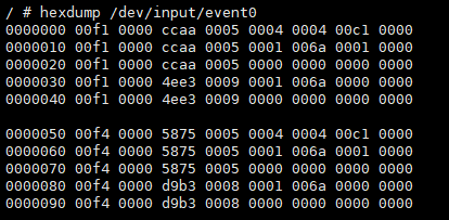
Figure 5-6: Data Received Under /dev/input/event0 -
Currently, it supports switching the IR decoding mode in user space. Check the files in the /sys/class/sstar directory. The configuration of several groups of IR devices corresponds to several IR nodes. echo [mode] > decode_mode can switch the IR decoding mode. The mode input value can be: 1→FULL, 2→RAW, 3→RC5, 4→SW.
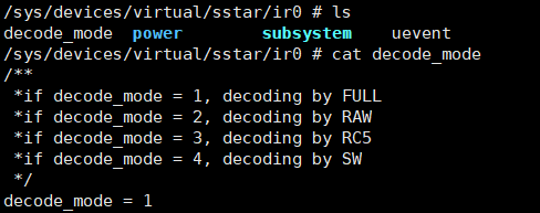
Figure 5-7: Cat /sys/class/sstar/ir0/decode_mode Results
6.5. Sample Code
Enter the driver/sstar/ir/ut path and enter the command make to compile ut_ir.c. The ut_ir file will be generated in this path.
ut_ir.c mainly obtains the input event type and key value by reading the event interface, and transmits the information to the user state through struct input_event. Every time the remote control sends an IR signal, the event type of input_event will change in the following order: EV_MSC->EV_KEY->EV_SYN->EV_KEY->EV_SYN.
| Type | Code | Value |
|---|---|---|
| EV_MSC | MSC_SCAN(0x4) | Code value |
| EV_SYN | SYN_REPORT (0x0) | 0x0 |
| EV_KEY | Key value corresponding to the code value in rc_map_table | 1: Press, 0: Lift |
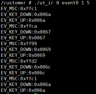
Copy the generated ut_ir file to the board and run it. Enter ./ut_ir [group][event][mode] [count], where count is the number of times the remote control button is pressed. For example, enter ./ut_ir 0 event0 1 5 to test the function when the IR0 decoding mode is FULL. Press the button of the remote control facing the IR, and the log prints the read press and lift signal and the related key value. As shown in Figure 5-8, the remote control test results, where EV_MSC is the code value of the remote control signal after IR decoding, and the EV_KEY_DONW/EV_KEY_UP value is the key value after the code value is converted through the rc-map-table.
7. API Refernece
No external API available at the moment.
8. FAQ
If the remote control does not trigger the Input event after being pressed, that is, hexdump /dev/input/event0 does not print any information, you can check from the following aspects:
8.1 IR Driver Cannot Receive IR Signal
-
Check whether padmux has been configured, see Configure Padmux.
-
Check whether kernel config is configured properly, see Configure Kennel Config.
-
Check whether
statusof DTS IR node isok. -
Check whether there is a short circuit in IR Receiver in the hardware schematic (such as JP55 in Figure 5-9).

Figure 5-9: IR Hardware Schematic -
Check the remote control waveform to determine whether the IR_IN signal conforms to the NEC and RC5 formats, and the current decoding mode matches the source signal.
8.2 EVENT Event Are not Triggered
-
EV_MISC event and EV_KEY event are not triggered. Check DTS's rc_map_table to see if the code value in the left column of the key-value pair is consistent with the one sent by the remote control.
-
EV_MISC event is triggered, but EV_KEY event is not triggered. Check DTS's rc_map_table to see if the code value in the left column of the key-value pair corresponds to the input event code in the right column and is supported by the kernel.
-
If the decoding mode is SW, confirm if the decoder of the protocol to which the remote control belongs is compiled.