Audio Development Guide
REVISION HISTORY
| Revision No. | Description |
Date |
|---|---|---|
| 1.0 | Initial release | 04/17/2024 |
Preface
This chapter mainly describes the relevant concepts and code structure of Audio.
1. Overview
1.1. Overview
This chapter guides users to understand the SigmaStar platform alsa architecture and usage methods, so as to achieve the purpose of preliminary use of alsa and locate audio problems.
The SigmaStar platform ALSA architecture complies with the standard ALSA architecture. The standard ALSA decoupling solution block diagram is as follows. Under the premise of maintaining the standard system architecture unchanged, private business behaviors are integrated and synchronized with the standard ASLA system, mainly involving two aspects: volume control solution & peripheral channel playback.
Complying with the standard alsa-lib to achieve decoupling is also the core of the decoupling solution. Provide interfaces for user-level applications (such as alsa-utils or refer to the example prog_ai_ao_demo) to call, and call the alsa standard interface to implement functions such as volume and device switching. The main solutions involved are as follows:
| Application   |       alsa-utils       |  |      tinyalsa            |
|               | aplay  arecord  amixer |  | tinyplay tinycap tinymix |
|----------------------------------------------------------------------|
| User Space    |       alsa-lib         |  |      tinyalsa-lib        |
|----------------------------------------------------------------------|
| Kernel Space  |               alsa Core & asoc core                  |
|----------------------------------------------------------------------|
| Device driver |                    sound driver                      |
|----------------------------------------------------------------------|
|                                      Hardware                        |
1.2. Concept
| Name | Description |
|---|---|
| DAI | Digital Audio Interfaces |
| CPU DAI | Audio Data Interface of the host, such as I2S, Spdif, Pdm, Tdm |
| CODEC DAI | Codec |
| DAI_LINK | Binds Cpu_Dai and Codec_Dai into one sound card, equivalent to Machine Driver |
| DMAENGINE | Dma transmission engine between CPU and I2S/Spdif etc., actually transfers data via Dma |
| DAPM | Dynamic audio power management, used to dynamically manage the power of codecs, etc., and configure switches based on the opening of the channel to minimize power consumption while ensuring functionality. |
| JACK | Headphone interface detection, most of which use the Codec's own detection mechanism, and a small part uses IO for simulation |
1.3. Audio ALSA Framework and Audio Topology Diagram
1.4. Code Structure
| Project | Function | Path |
|---|---|---|
| Sound soc | Mainly contains common code, including dapm control, jack, dmaengine, core, etc. | sound/soc/ |
| Sigmastar platform | Sigmastar platform cpu dai driver and custom sound card machine driver | sound/soc/sstar |
| Codec driver | All codec driver storage locations | sound/soc/codecs |
1.5. Channel Parameter Support
| Channel Type | Sampling Rate (kHz) | Bit Width | Channel | PCM Format |
|---|---|---|---|---|
| WDMA1 | 8 / 16 / 32 / 44.1 / 48 / 96 / 192 | 16 / 24 / 32 | 1 / 2 / 4 / 8 / 16 | NA |
| WDMA2 | 8 / 16 / 32 / 44.1 / 48 / 96 / 192 | 16 / 24 / 32 | 1 / 2 / 4 / 8 | NA |
| I2S0_TX | 8 / 16 / 32 / 44.1 / 48 / 96 / 192 | 16 / 24 / 32 | 1 / 2 / 4 / 8 | standard,left justified |
| I2S0_RX | 8 / 16 / 32 / 44.1 / 48 / 96 / 192 | 16 / 24 / 32 | 1 / 2 / 4 / 8 | standard,left justified |
| I2S0_MCK | 11289.6 / 12288 / 16384 / 19200 / 24000 / 48000 | NA | NA | NA |
| I2S1_TX | 8 / 16 / 32 / 44.1 / 48 / 96 / 192 | 16 / 24 / 32 | 1 / 2 | standard,left justified |
| I2S1_RX | 8 / 16 / 32 / 44.1 / 48 / 96 / 192 | 16 / 24 / 32 | 1 / 2 | standard,left justified |
| I2S1_MCK | 11289.6 / 12288 / 16384 / 19200 / 24000 / 48000 | NA | NA | NA |
| I2S2_TX | 8 / 16 / 32 / 44.1 / 48 / 96 / 192 | 16 / 24 / 32 | 1 / 2 | standard,left justified |
| I2S2_RX | 8 / 16 / 32 / 44.1 / 48 / 96 / 192 | 16 / 24 / 32 | 1 / 2 | standard,left justified |
| I2S2_MCK | 11289.6 / 12288 / 16384 / 19200 / 24000 / 48000 | NA | NA | NA |
| LINE_IN | 8 / 16 / 32 / 48 | 16 / 24 / 32 | 1 / 2 | NA |
| LINE_OUT | 8 / 11.025 / 12 / 16 / 22.05 / 24 / 32 / 44.1 / 48 | 16 / 24 / 32 | 1 / 2 | NA |
| SPDIF_RX | 32 / 44.1 / 48 / 88.2 / 96 / 192 | 16 / 24 | 2 | LPCM / RAW |
| DMIC | 8 / 16 / 32 / 48 | 16 / 24 / 32 | 2 / 4 / 6 / 8 | PDM |
| ECHO | 8 / 16 / 32 / 48 | 16 / 24 / 32 | 2 | NA |
2. Audio Development Guide
This chapter describes how to add a sound card and debug a sound card. A sound card consists of cpu_dai, codec_dai, and dai_link, which correspond to the driver of cpu dai, such as bach driver, bach2 driver; codec driver; dai_link driver, which is machine driver, such as sound/soc/sstar/pcupid/sstar_asoc_card.c.
If you need to connect to a third-party Codec Alsa Driver, please refer to Connect to a third-party Codec Driver
If you only need to configure I2S, please refer to the I2S Format setting in DTS Configuration
2.1. Keyword Description
-
DMA
DMA stands for direct memory access. DMA transfer copies data from one address space to another, providing high-speed data transfer between peripherals and memory or between memory and memory. When the CPU initializes the transfer action, the transfer action itself is implemented and completed by the DMA controller. The DMA transfer method does not require the CPU to directly control the transfer, nor does it have the scene retention and scene recovery process like the interrupt processing method. It opens a direct data transmission channel for RAM and IO devices through hardware, greatly improving the efficiency of the CPU.
-
WDMA
WDMA stands for direct memory access writer.
-
RDMA
RDMA stands for direct memory access reader.
-
MUX
MUX is a multiplexer data selector. In multi-channel data transmission, it is a circuit that can select any of the multiple channels as needed. The Mux in front of WDMA selects multiple data sources for WDMA, and can support the selection of ½/4 data sources (the data sources can be the same or different). Each data source has 2 channels, that is, 2/4/8 channels of data are selected to be written to DRAM by WDMA, playing the role of a multiplexer. The Mux close to the output peripheral interface (I2S_TX/DAC, etc.) realizes the function of selecting one from multiple.
-
DPGA
DPGA stands for digital programmable gain amplifier, which is a very versatile amplifier whose amplification factor can be controlled by program as needed.
-
DMIC
DMIC stands for digital microphone interface. The audio codec only provides the DMIC interface, not the complete DMIC. The DMIC interface provides the clock signal required for DMIC operation and receives the PDM signal from the DMIC.
-
ADC
ADC stands for analog digital conversion, which is an electronic component that converts analog signals into digital signals.
-
I2S
I2S, the inter-IC sound integrated circuit built-in audio bus, is a bus standard developed by Philips for audio data transmission between digital audio devices. Sigmastar's I2S bus only supports the standard I2S data format and the left-aligned I2S data format. It also supports TDM (Time-Division Multiplexing) technology, which interweaves different signals in different time periods and transmits them along the same channel, and can simultaneously support ½/4/8 channel data transmission.
-
DAC
DAC stands for digital analog conversion, which is an electronic component that converts digital signals into analog signals.
-
SPDIF_RX
Sony/Philips Digital InterFace (SPDIF for short), can transmit LPCM streams and surround sound compressed audio signals such as Dolby Digital and DTS.
-
SRC
SRC stands for sample rate convert, which converts the sampling rate of voice digital signals.
-
Mixer
Mixer is mixing, using a linear superposition averaging algorithm (if the volume of a certain audio channel is particularly low, the volume of the entire mixing result will be lowered). After mixing, the output sampling rate can be set.
-
device (audio input/output device)
The device of audio output refers to the RDMA of audio codec. Device is ASOC's abstraction of DMA in audio codec. Only one device is mounted under one card. RDMA in audio codec and output device are in one-to-one correspondence. For example, card 0 and device 0 corresponds to RDMA0 in audio codec, card 1 and device 0 corresponds to RDMA1 in audio codec, and so on. WDMA and input device are also in one-to-one correspondence. For example, card 0 and device 0 corresponds to WDMA0 in audio codec, card 1 and device 0 corresponds to WDMA1 in audio codec. ASOC's data streams are all connected in series with DMA as the center.
ASOC also includes another type of device, that is, the input device directly sends the data stream to the output device without going through DMA, such as (AMIC -> DAC). This type of device is called passthrough, and is currently only supported by the AI_MCH_VIR_SEL/AO_VIR_MUX_SEL nodes.
-
interface (audio output peripheral)
The output interface refers to the abstraction of the audio output peripheral interface of the audio codec, such as DAC/I2S_TX and other interfaces.
The input interface refers to the abstraction of the audio input peripheral interface of the audio codec, such as the AMIC/DMIC/I2S_RX/Spdif_rx interfaces.
-
output attach
Output attach refers to mounting the interface to RDMA. For output devices, attach is to connect the RDMA output signal to a specific interface so that the peripheral device can output audio signals. Output supports dynamic attach.
Hardware mixing: When the same output interface is attached to two output devices, the output of the output interface is the result of mixing the outputs of the two output devices .
Passthrough: When the usage scenario includes passthrough, you need to attach the input first and then attach the output, otherwise it will not work properly.
Distribution: When multiple output interfaces are attached to one output device, the signal output from RDMA is gain-adjusted by DPGA and then divided into multiple branches to reach each interface, and each peripheral outputs sound at the same time.
-
input attach
Input attach means to mount the interface to the MUX corresponding to WDMA, that is, to associate the device with the interface. For input devices, attach is to set the MUX corresponding to WDMA, and select which interface data can pass through the MUX, and WDMA will do the subsequent data movement. Input does not support dynamic attach.
-
detach
Detach means disconnecting the interface from RDMA/WDMA.
-
output echo
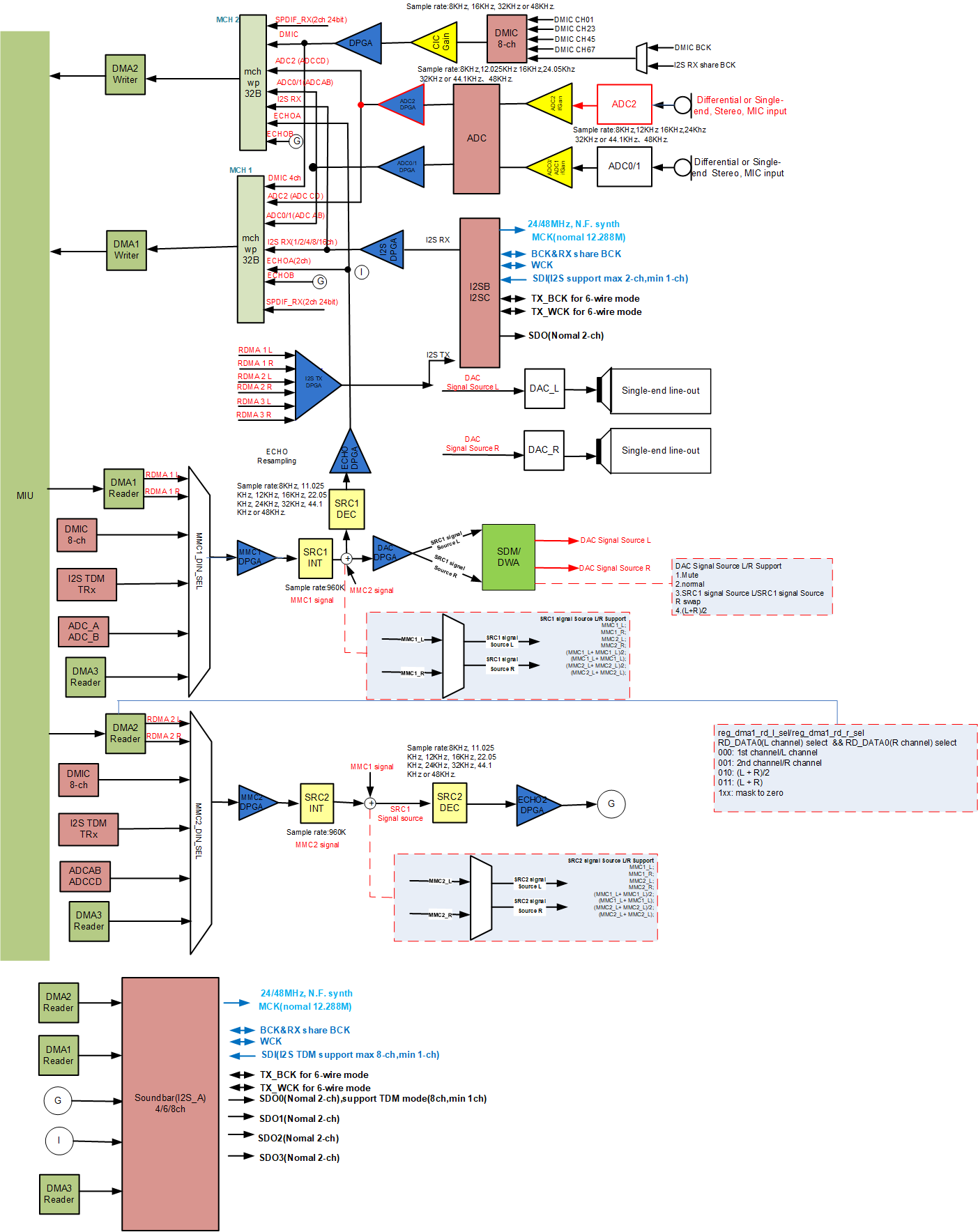
The echo of output refers to the echo reference data of AEC. As can be seen from the ALSA block diagram, the input of SRC is the signal output by RDMA and amplified by DPGA, and the output of SRC is the signal after resampling the input, which can be sent to WDMA through multi channel as the echo reference data of AEC algorithm.
-
input echo
The input echo refers to the AEC reference data provided by the audio codec. For input devices, echo refers to the output signal of SRC in the ALSA block diagram. For output devices, echo refers to connecting the output of the output device to the input of SRC. The following figure uses a simple block diagram to show the data flow of the input device and output device using echo at the same time, so that the application can obtain the aligned AEC far end and near end data.
_________ ___| ADC | <- AMIC _____ ________ _______ | ————————— | APP | <- | WDMA 0 | <- | MCH | <--| ————— ———————— ——————— | ________ |___ | SRC | ———————— ^ |\ | _____ ________ | \ | _____ | APP | -> | RDMA 0 | -> |DPGA------------------> | DAC | -> Speaker ————— ———————— | / ————— |/ -
GAIN
AI Gain is divided into two categories in the ALSA architecture. One is the DPGA Gain associated with the Device, which is the DPGA in the ALSA block diagram. The other is the Gain unique to the Interface. Currently, the Interfaces with Gain are ADC and Dmic. Interface. For AI, if the Interface itself does not have an independent Interface Gain and is not connected to Dpga, then Gain cannot be set. For AO, Gain can only be adjusted through Dpga.
DPGA stands for Digital Programmable Gain Amplifier, which is a very versatile amplifier whose amplification factor can be controlled by program as needed.
-
format
That is, what data format is used to represent an audio sample. Currently, the format S16_LE/S24_3LE/S32_LE is supported.
-
sample rate
Input refers to the number of times the recording device samples the analog signal per unit time. The higher the sampling frequency, the more realistic and natural the waveform of the mechanical wave will be.
For output, it indicates the playback sampling rate.
-
period size
For output, period size indicates the default start condition (playback will start only when the number of samples in the cache is greater than period size)
-
I2S Mode
It determines the working mode of I2S, whether it is standard I2S mode or TDM I2S mode (2 channels or multi-channel), whether it is Master or Slave (Master provides synchronous clock, Slave receives synchronous clock). Generally speaking, there is no restriction on the working mode, as long as it can match the external codec clock.
-
I2S BitWidth
The bit width of the received and sent data currently supports 16/24/32bit.
-
I2S format
That is, the I2S alignment method. Currently, only I2S Philips and Left-justified alignment are supported.
I2S Philips alignment format, the first data bit of the sample data appears after the first BCLK (serial clock) jump of WCLK (left and right channel switching clock).
Left-justified alignment format, the first data bit of the sample data appears in the first BCLK (serial clock) jump of the WCLK (left and right channel switching clock), and the polarity of WCLK is opposite to the I2S Philips alignment format.
-
MCLK
It is called the master clock, also called the system clock. It is usually 256 or 384 times the sampling frequency. It is used to make the systems synchronized better, but it is not necessary. Currently, it supports 12.288M, 16.384M, 18.432M, 19.2M, 24M, 48M, etc.
-
4-wire/6-wire Mode
Sigmastar's I2S has 2 wiring modes.
One is the 4-wire mode, including RX_WCK, RX_BCK, RX_SDI and TX_SDO. In this mode, TX does not have an independent clock, and all clocks are provided by RX. Therefore, in this mode, TX needs to rely on RX to use, and TX cannot be used alone, and the parameters of I2S TX need to be consistent with I2S RX.
The other is the 6-wire mode, including RX_WCK, RX_BCK, RX_SDI, TX_WCK, TX_BCK, and TX_SDO. In this mode, RX and TX are independent and unrelated.
The choice of 4-wire/6-wire Mode needs to be determined according to the specific scenario. The RX/TX of the same I2S group cannot be set to 4-wire Mode on one side and 6-wire Mode on the other side.
-
Slot
Slot indicates the number of channels transmitted by I2S. Currently, 2 slots are supported in I2S mode and 4/8/16 slots are supported in TDM mode. However, the valid data of I2S TX is 2 slots. When the number of slots for I2S TX is set to be greater than 2, except for slot 0 and slot 1, the others are invalid data.
-
Passthrough
Passthrough means that the input device directly sends the data stream to the output device without going through DMA. For example, ADC -> DAC:
/| ______ ------- <- DPGA - <- | | ADC | <- AMIC | \| —————— | | V |\ _______ ---> | - DPGA ->| | |/ | | _____ | Mixer | -> | DAC | -> Speaker _____ ________ |\ | | ————— | MIU | -> | RDMA 0 | -> - DPGA -> | | ————— ———————— |/ ——————— -
Input's attach node
AI_MCH_01_SEL: MUX channel 0/1
-
Output's attach node
DMA is used for non-hardware mixing, DMA+SRC is used for hardware mixing
-
CHANNEL_MODE
STEREO: Normal stereo mode
DOUBLE_MONO: The left and right channels are output as the same mono data
DOUBLE_LEFT: The left and right channels are output as left channel data
DOUBLE_RIGHT: The left and right channels are output as right channel data
EXCHANGE: The left and right channels output the data exchanged between the left and right channels
ONLY_LEFT: Only the left channel is output as mono data
ONLY_RIGHT: Only the right channel is output as mono data
DOUBLE_NONE: Mute
2.2. simple-card
Simple card is a simple and universal machine driver. If the simple-card framework can meet your needs, it is recommended to use the simple card framework first, which is simple, convenient, and easy to use. When using simple-card, you need to manually disable asoc_sound.
-
Open ASoC Simple sound card in menuconfig
If simple-card is enabled, the customized machine-driver will not take effect.
make menuconfig Device Drivers ---> <*> Sound card support ---> <*> Advanced Linux Sound Architecture ---> <*> ALSA for SoC audio support ---> <*> ASoC support for SigmaStar <*> ASoC Simple sound card support -
Add Simple Card Node to the product's DTS
asoc_sound_simple {
    status = "ok";
    compatible = "simple-audio-card";
    simple-audio-card,format = "i2s";
    simple-audio-card,name = "sigmastar,asoc-card";
    simple-audio-card,mclk-fs = <256>;
    simple-audio-card,cpu {
        sound-dai = <&bach1>;
    };
    simple-audio-card,codec {
        sound-dai = <&dummy_codec1>;
    };
};
bach1: bach1 {
    status = "ok";
    compatible = "sstar,bach";
    sound-dma = <&dma1>;
    #sound-dai-cells = <0>;
    reg = <0x1F2A0400 0x800>;
};
2.3. Custom Machine Driver
- Use custom Machine Driver by default.
make menuconfig
Device Drivers --->
    <*> Sound card support --->
        <*> Advanced Linux Sound Architecture --->
            <*> ALSA for SoC audio support --->
                <*> ASoC support for SigmaStar
                < > ASoC Simple sound card
2.4. Connecting to a third-party Codec Driver
2.4.1. Connecting to third-party Codec Driver based on custom Machine Driver
-
Add codec driver. For example, when add sound/soc/codec/es8326.c, if you do not need to use the I2S interface, you can use sstar_dummy_codec.c by default.
-
Modify sound/soc/codec/Kconfig and Makefile to include the added codec driver in the driver compilation.
sound/soc/codec/Kconfig: config SND_SOC_ES8326 tristate "Everest Semi ES8326 CODEC" depends on I2C sound/soc/codec/Makefile: snd-soc-es8326-objs := es8326.o obj-$(CONFIG_SND_SOC_ES8326) += snd-soc-es8326.o -
Enable card and codec in menuconfig
make menuconfig Device Drivers ---> <*> Sound card support ---> <*> Advanced Linux Sound Architecture ---> <*> ALSA for SoC audio support ---> <*> ASoC support for SigmaStar CODEC drivers ---> <*> SSTAR DUMMY AUX CODEC driver <*> Everest Semi ES8326 CODEC -
Add Card Node in the product's DTS and modify the settings in DTSI as needed. If an I2S interface is used, set the relevant I2S format in DTS. For the setting rules of the relevant format, please refer to Device Tree Configuration.
soc {
    sound {
        // I2S RX0 TDM
        i2s-rx0-tdm-mode    = <2>;  // 1:master       2:slave
        i2s-rx0-tdm-fmt     = <1>;  // 1:i2s justify  2:left justify
        i2s-rx0-tdm-wiremode = <2>; // 1:4wire        2:6 wire
        i2s-rx0-channel  = <4>;
        i2s-rx0-tdm-ws-pgm = <0>; // 0: OFF  1: ON
        i2s-rx0-tdm-ws-width = <0>; // value: 0~31 (width = value + 1)
        i2s-rx0-tdm-ws-inv = <0>; // 0: normal  1: inverse WCK
        i2s-rx0-tdm-bck-inv = <0>; // 0: normal  1: inverse BCK
        i2s-rx0-tdm-ch-swap = <0 0 0>; // 0: OFF  1: ON

        // I2S TX0 TDM
        i2s-tx0-tdm-mode    = <1>;  // 1:master       2:slave
        i2s-tx0-tdm-fmt     = <1>;  // 1:i2s justify  2:left justify
        i2s-tx0-tdm-wiremode = <2>; // 1:4wire        2:6 wire
        i2s-tx0-channel  = <4>;
        i2s-tx0-tdm-ws-pgm = <0>; // 0: OFF  1: ON
        i2s-tx0-tdm-ws-width = <0>; // value: 0~31 (width = value + 1)
        i2s-tx0-tdm-ws-inv = <0>; // 0: normal  1: inverse WCK
        i2s-tx0-tdm-bck-inv = <0>; // 0: normal  1: inverse BCK
        i2s-tx0-tdm-ch-swap = <0 0 0>; // 0: OFF  1: ON
        i2s-tx0-tdm-active-slot = <0xFF>; // value: 0x00 ~ 0xFF (bit0->slot0, bit1->slot1, ... )

        status = "ok";
    };

    asoc_sound {
        compatible = "sstar, asoc-card";
        sstar-audio-card,name = "sigmastar,asoc-card";
        sstar-audio-card,cpu {
            sound-dai = <&bach1>;
        };
        sstar-audio-card,codec {
            sound-dai = <&dummy_codec1>, <&es8326_1>;
        };
    };

    bach1:bach1 {
        mclk0-freq = <24000000>;
        status = "okay";
    };

    i2c1{
        status = "ok";
        es8326_1: es8326_1@18{
            status = "ok";
            #sound-dai-cells = <0>;
            //interrupts = <GIC_SPI  INT_FIQ_DUMMY_31 IRQ_TYPE_LEVEL_HIGH>;
            compatible = "everest,es8326_1";
            codec-name = "ES8326_1 HiFi";
            clocks = <&CLK_mck_12p288m>;
            clock-names = "mclk";
            reg = <0x18>;
        };
    };
};
2.4.2. Connecting to third-party Codec Driver based on simple-card
-
Add codec driver. For example, add sound/soc/codec/es8386.c.
Modify sound/soc/codec/Kconfig and Makefile to include the added codec driver in driver compilation.
sound/soc/codec/Kconfig: config SND_SOC_ES8326 tristate "Everest Semi ES8326 CODEC" depends on I2C sound/soc/codec/Makefile: snd-soc-es8326-objs := es8326.o obj-$(CONFIG_SND_SOC_ES8326) += snd-soc-es8326.o -
Enable ASoC Simple sound card and codec in menuconfig.
If simple-card is enabled, the custom machine-driver will not take effect.
make menuconfig Device Drivers ---> <*> Sound card support ---> <*> Advanced Linux Sound Architecture ---> <*> ALSA for SoC audio support ---> <*> ASoC support for SigmaStar <*> ASoC Simple sound card support CODEC drivers ---> <*> SSTAR DUMMY AUX CODEC driver <*> Everest Semi ES8326 CODEC -
Add Simple Card Node in the product's DTS.
asoc_sound_simple {
    status = "ok";
    compatible = "simple-audio-card";
    simple-audio-card,format = "i2s";
    simple-audio-card,name = "sigmastar,asoc-card";
    simple-audio-card,mclk-fs = <256>;
    simple-audio-card,cpu {
        sound-dai = <&bach1>;
    };
    simple-audio-card,codec {
        sound-dai = <&es8326_1>;
    };
};
bach1: bach1 {
    status = "ok";
    compatible = "sstar,bach";
    sound-dma = <&dma1>;
    #sound-dai-cells = <0>;
    reg = <0x1F2A0400 0x800>;
    mclk-freq = <12288000>;
};
i2c1{
    status = "ok";
    es8326_1: es8326_1@18{
        status = "ok";
        #sound-dai-cells = <0>;
        //interrupts = <GIC_SPI  INT_FIQ_DUMMY_31 IRQ_TYPE_LEVEL_HIGH>;
        compatible = "everest,es8326_1";
        codec-name = "ES8326_1 HiFi";
        clocks = <&CLK_mck_12p288m>;
        clock-names = "mclk";
        reg = <0x18>;
    };
};
3. Sound Card Control
3.1. Volume Control
-
All channels use the mixer control interface to complete volume adjustment.
-
The volume is applied to the DPGA connected to the interface
Playback:
________     _________     |\              _______
|  MIU | -> | RDMA 0  | -> |  - DPGA  ->  |  DAC  | -> Speaker
————————     —————————     |/              ———————

Capture:
________     _________      _______            /|     _____
|  MIU | <- | WDMA 0  | <- |  MUX  | <- DPGA -  | <- | ADC | <- AMIC
————————     —————————      ———————            \|     —————
-
Adjust the mute switch
control node
console:/ # tinymix -D 0 contents  or    tinymix -D 1 contents
Number of controls: 62
ctl type    num   name                                    value
0   BOOL    1     DAC Mute                                Off
1   BOOL    1     I2S_TXA_01 Mute                         Off
2   BOOL    1     I2S_TXA_23 Mute                         Off
3   BOOL    1     I2S_TXA_45 Mute                         Off
4   BOOL    1     I2S_TXA_67 Mute                         Off
5   BOOL    1     I2S_TXB_01 Mute                         Off
6   BOOL    1     I2S_TXC_01 Mute                         Off
7   BOOL    1     ADC_A Mute                              Off
8   BOOL    1     ADC_B Mute                              Off
9   BOOL    1     DMIC_01 Mute                            Off
10  BOOL    1     DMIC_23 Mute                            Off
11  BOOL    1     DMIC_45 Mute                            Off
12  BOOL    1     DMIC_67 Mute                            Off
13  BOOL    1     I2S_RXA_01 Mute                         Off
14  BOOL    1     I2S_RXA_23 Mute                         Off
15  BOOL    1     I2S_RXA_45 Mute                         Off
16  BOOL    1     I2S_RXA_67 Mute                         Off
17  BOOL    1     I2S_RXB_01 Mute                         Off
18  BOOL    1     I2S_RXC_01 Mute                         Off
19  BOOL    1     SPDIF_RX_01 Mute                        Off
Adjustment range:
- Adjustment range (Off/On), On means mute, Off means not mute, and the default state is Off.
-
Adjust DPGA Gain
control node
console:/ # tinymix -D 0 contents  or    tinymix -D 1 contents
Number of controls: 62
ctl type    num   name                                    value
20  INT     2     DAC Playback Volume                     511, 511 (range 0->1023)
21  INT     2     I2S_TXA_01 Playback Volume              511, 511 (range 0->1023)
22  INT     2     I2S_TXA_23 Playback Volume              511, 511 (range 0->1023)
23  INT     2     I2S_TXA_45 Playback Volume              511, 511 (range 0->1023)
24  INT     2     I2S_TXA_67 Playback Volume              511, 511 (range 0->1023)
25  INT     2     I2S_TXB_01 Playback Volume              511, 511 (range 0->1023)
26  INT     2     I2S_TXC_01 Playback Volume              511, 511 (range 0->1023)
27  INT     2     SIDETONE Playback Volume                0, 0 (range 0->1023)
28  INT     2     ADC_A Capture Volume                    511, 511 (range 0->1023)
29  INT     2     ADC_B Capture Volume                    511, 511 (range 0->1023)
30  INT     2     I2S_RXA_01 Capture Volume               511, 511 (range 0->1023)
31  INT     2     I2S_RXA_23 Capture Volume               511, 511 (range 0->1023)
32  INT     2     I2S_RXA_45 Capture Volume               511, 511 (range 0->1023)
33  INT     2     I2S_RXA_67 Capture Volume               511, 511 (range 0->1023)
34  INT     2     I2S_RXB_01 Capture Volume               511, 511 (range 0->1023)
35  INT     2     I2S_RXC_01 Capture Volume               511, 511 (range 0->1023)
36  INT     2     DMIC_01 Capture Volume                  511, 511 (range 0->1023)
37  INT     2     DMIC_23 Capture Volume                  511, 511 (range 0->1023)
38  INT     2     DMIC_45 Capture Volume                  511, 511 (range 0->1023)
39  INT     2     DMIC_67 Capture Volume                  511, 511 (range 0->1023)
40  INT     2     ECHO_01 Capture Volume                  511, 511 (range 0->1023)
41  INT     2     SPDIF_RX_01 Capture Volume              511, 511 (range 0->1023)
Adjustment range:
- The two values represent the left channel and the right channel respectively. Range (0~1023), minimum value is -63.875db, maximum value is 64db, step length is 0.125db. The default value is 511, which represents a gain of 0db.
Adjustment method:
References for tinyalsa usage:
The dpga gain of DAC Playback Volume is set to 911
console:/ # tinymix -D 0 set "DAC Playback Volume" 911 911

alsa-utils usage reference:
console:/ # ./amixer cset name='DAC Playback Volume' 911,911

Before setup:
console:/ # tinymix -D 0 contents
Number of controls: 62
ctl type    num   name                                    value
20  INT     2     DAC Playback Volume                     511, 511 (range 0->1023)

After setup:
console:/ # tinymix -D 0 contents
Number of controls: 62
ctl type    num   name                                    value
20  INT     2     DAC Playback Volume                     911, 911 (range 0->1023)
-
Adjust ANOLG Gain
A control node that supports volume adjustment
console:/ # tinymix -D 0 contents  or    tinymix -D 1 contents
Number of controls: 62
ctl type    num   name                                    value
42  INT     2     ADC_A ANOLG GAIN                        0, 0 (range 0->19)
43  INT     2     ADC_B ANOLG GAIN                        0, 0 (range 0->19)
Adjustment range:
- The two values represent the left channel and the right channel respectively. Range (0~19), minimum value is 0db, maximum value is 57db, step length is 3db. The default value is 0, which means a gain of 0db.
Adjustment method:
The gain of left and right channels of ADC_A ANOLG GAIN is set to 10
console:/ # tinymix -D 0 set "ADC_A ANOLG GAIN" 10 10

The gain of left and right channels of ADC_B ANOLG GAIN is set to 10
console:/ # tinymix -D 0 set "ADC_B ANOLG GAIN" 10 10

alsa-utils usage reference:
console:/ # ./amixer cset name='ADC_A ANOLG GAIN' 10 10
console:/ # ./amixer cset name='ADC_B ANOLG GAIN' 10 10

Before setup:
console:/ # tinymix -D 0 contents
Number of controls: 62
ctl type    num   name                                    value
42  INT     2     ADC_A ANOLG GAIN                        0, 0 (range 0->19)
43  INT     2     ADC_B ANOLG GAIN                        0, 0 (range 0->19)

After setup:
console:/ # tinymix -D 0 contents
Number of controls: 62
ctl type    num   name                                    value
42  INT     2     ADC_A ANOLG GAIN                        10, 10 (range 0->19)
43  INT     2     ADC_B ANOLG GAIN                        10, 10 (range 0->19)
3.2. Device Tree Configuration
-
Master-slave mode
Property name Description Value range i2s-rx0-tdm-mode Configure master-slave mode 1: Master mode
2: Slave modei2s-tx0-tdm-mode Configure master-slave mode 1: Master mode
2: Slave modei2s-rx1-tdm-mode Configure master-slave mode 1: Master mode
2: Slave modei2s-tx1-tdm-mode Configure master-slave mode 1: Master mode
2: Slave modei2s-rx2-tdm-mode Configure master-slave mode 1: Master mode
2: Slave modei2s-tx2-tdm-mode Configure master-slave modes 1: Master mode
2: Slave mode -
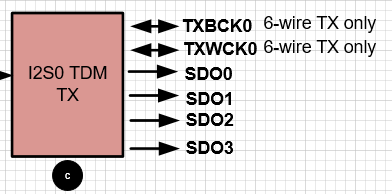
I2S Soundbar
Property name Description Value range i2s-tx0-soundbar-mode Configure Soundbar mode 1: On
2: OffWhen Soundbar is turned on, I2S data will output audio data from SDO0/½/3 at the same time
-
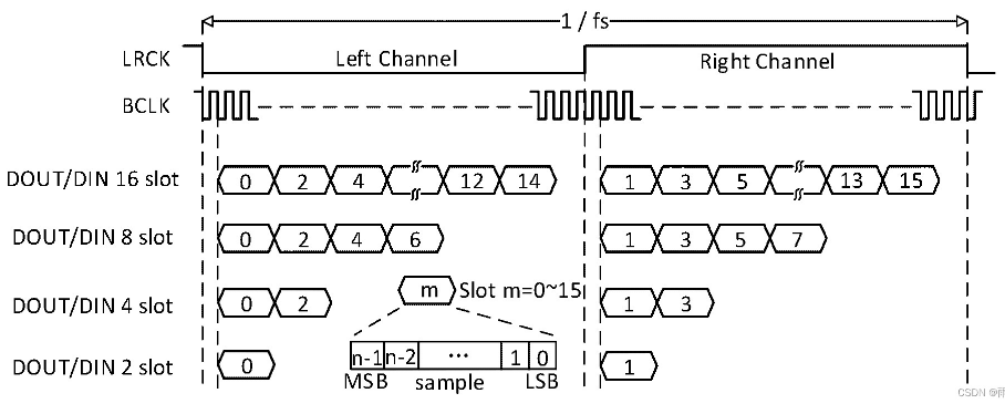
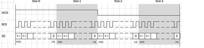
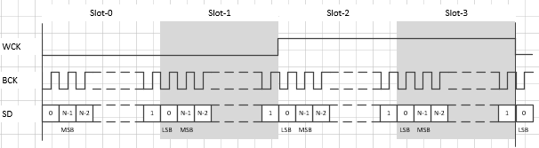
I2S format
Property name Description Value range i2s-rx0-tdm-fmt Configure I2S format 1: Standard format
2: Left-aligned formati2s-tx0-tdm-fmt Configure I2S format 1: Standard format
2: Left-aligned formati2s-rx1-tdm-fmt Configure I2S format 1: Standard format
2: Left-aligned formati2s-tx1-tdm-fmt Configure I2S format 1: Standard format
2: Left-aligned formati2s-rx2-tdm-fmt Configure I2S format 1: Standard format
2: Left-aligned formati2s-tx2-tdm-fmt Configure I2S format 1: Standard format
2: Left-aligned formatStandard format:
I2S mode is a special case of left-aligned format, also called PHILIPS mode, which is a change from the standard left-aligned format with a delay of one clock bit.
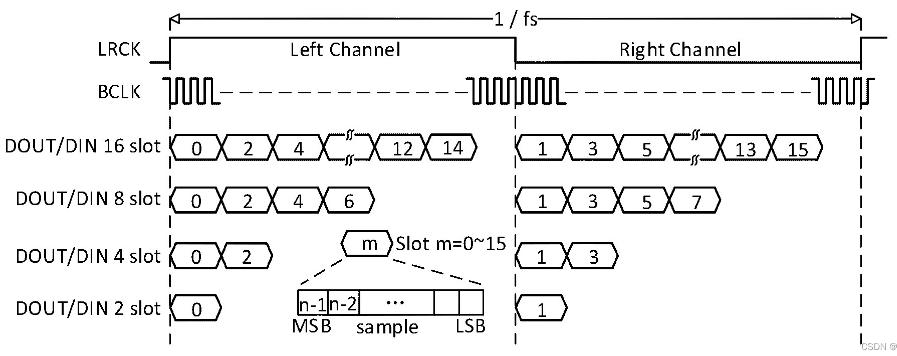
Left-aligned format:
Compared with the standard format, it can be seen that the MSB of the data in the standard left-aligned format is not delayed by one clock relative to BCLK.
-
I2S wiremode
Property name Description Value range i2s-rx0-tdm-wiremode Configure I2S wiring mode 1: 4-wire mode
2: 6-wire modei2s-tx0-tdm-wiremode Configure I2S wiring mode 1: 4-wire mode
2: 6-wire modei2s-rx1-tdm-wiremode Configure I2S wiring mode 1: 4-wire mode
2: 6-wire modei2s-tx1-tdm-wiremode Configure I2S wiring mode 1: 4-wire mode
2: 6-wire modeFour-wire mode:
When the external codec provides the clock, both i2s-rx-tdm-mode and i2s-tx-tdm-mode are set to slave mode. When the external codec does not provide a clock, both i2s-rx-tdm-mode and i2s-tx-tdm-mode are set to master mode. During lookback (TXRX docking), both i2s-rx-tdm-mode and i2s-tx-tdm-mode are set to master mode.
-
Number of I2S channels
Property name Description Value range i2s-rx0-channel Configure I2S channel number 1, 2, 4, 8 i2s-tx0-channel Configure I2S channel number 1, 2, 4, 8 i2s-rx1-channel Configure I2S channel number 1, 2 i2s-tx1-channel Configure the number of I2S channels 1, 2 i2s-rx2-channel Configure I2S channel number 1, 2 i2s-tx2-channel Configure the number of I2S channels 1, 2 -
I2S tdm configuration
Property name Description Value range i2s-rx0-tdm-ws-pgm TDM programmable mode 0: OFF
1: ONi2s-tx0-tdm-ws-pgm TDM programmable mode 0: OFF
1: ONi2s-rx1-tdm-ws-pgm TDM programmable mode 0: OFF
1: ONi2s-tx1-tdm-ws-pgm TDM programmable mode 0: OFF
1: ONi2s-rx2-tdm-ws-pgm TDM programmable mode 0: OFF
1: ONi2s-rx2-tdm-ws-pgm TDM programmable mode 0: OFF
1: ONi2s-rx0-tdm-ws-width Configure the width of tdm WCK 0~31 (width = value + 1) i2s-tx0-tdm-ws-width Configure the width of tdm WCK 0~31 (width = value + 1) i2s-rx1-tdm-ws-width Configure the width of tdm WCK 0~31 (width = value + 1) i2s-tx1-tdm-ws-width Configure the width of tdm WCK 0~31 (width = value + 1) i2s-rx2-tdm-ws-width Configure the width of tdm WCK 0~31 (width = value + 1) i2s-tx2-tdm-ws-width Configure the width of tdm WCK 0~31 (width = value + 1) Example:
i2s-rx0-tdm-ws-pgm = <0>;
i2s-rx0-tdm-ws-width = <0>;
i2s-tx0-tdm-ws-pgm = <1>;
i2s-tx0-tdm-ws-width = <0xf>;
If the pgm:width attribute is not enabled, the WCK duty cycle is fixed at 50%.
Open pgm: At this time, the width attribute takes effect, and the WCK width is (width+1)*bclk
-
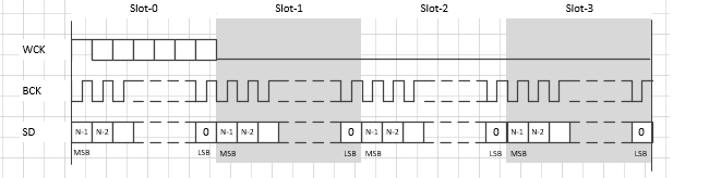
I2S wck flip
Property name Description Value range i2s-rx0-tdm-ws-inv I2S wck flip 0: No flip
1: Flipi2s-tx0-tdm-ws-inv I2S wck flip 0: No flip
1: Flipi2s-rx1-tdm-ws-inv I2S wck flip 0: No flip
1: Flipi2s-tx1-tdm-ws-inv I2S wck flip 0: No flip
1: Flipi2s-rx2-tdm-ws-inv I2S wck flip 0: No flip
1: Flipi2s-tx2-tdm-ws-inv I2S wck flip 0: No flip
1: FlipNo flip:

Flip:
-
I2S rx-ch-swap
Property name Description Value range i2s-rx0-tdm-ch-swap Configure tx i2s channel swap <0 0 0 0>
<0 1 0 0>
<1 0 0 0>
<1 1 0 0>i2s-tx0-tdm-ch-swap Configure tx i2s channel swap <0 0 0 0>
<0 1 0 0>
<1 0 0 0>
<1 1 0 0>i2s-rx1-tdm-ch-swap Configure rx i2s channel swap <0 0 0 0>
<0 1 0 0>
<1 0 0 0>
<1 1 0 0>i2s-tx1-tdm-ch-swap Configure tx i2s channel swap <0 0 0 0>
<0 1 0 0>
<1 0 0 0>
<1 1 0 0>i2s-rx2-tdm-ch-swap Configure rx i2s channel swap <0 0 0 0>
<0 1 0 0>
<1 0 0 0>
<1 1 0 0>i2s-tx2-tdm-ch-swap Configure tx i2s channel swap <0 0 0 0>
<0 1 0 0>
<1 0 0 0>
<1 1 0 0>Example:
i2s-rx0-tdm-ch-swap = <0 0 0 0>;
i2s-tx0-tdm-ch-swap = <0 1 0 0>;

echo rx/tx nTdm -swap <0 0 0 0> => DATA0|DATA1|DATA2|DATA3|DATA4|DATA5|DATA6|DATA7
echo rx/tx nTdm -swap <0 1 0 0> => DATA2|DATA3|DATA0|DATA1|DATA6|DATA7|DATA4|DATA5
echo rx/tx nTdm -swap <1 0 0 0> => DATA4|DATA5|DATA6|DATA7|DATA0|DATA1|DATA2|DATA3
echo rx/tx nTdm -swap <1 1 0 0> => DATA6|DATA7|DATA4|DATA5|DATA2|DATA3|DATA0|DATA1
echo rx/tx nTdm -swap <0 0 1 0> => DATA0|DATA2|DATA4|DATA6|DATA1|DATA3|DATA5|DATA7
echo rx/tx nTdm -swap <0 1 1 0> => DATA2|DATA0|DATA6|DATA4|DATA3|DATA1|DATA7|DATA5
echo rx/tx nTdm -swap <1 0 1 0> => DATA4|DATA6|DATA0|DATA2|DATA5|DATA7|DATA1|DATA3
echo rx/tx nTdm -swap <1 1 1 0> => DATA6|DATA4|DATA2|DATA0|DATA7|DATA5|DATA3|DATA1
-
I2S tx valid channel
Property name Description Value range i2s-tx0-tdm-active-slot Configure I2S tx active channel 0x00 ~ 0xFF (bit0->slot0, bit1->slot1, ... ) i2s-tx1-tdm-active-slot Configure I2S tx active channel 0x00 ~ 0xFF (bit0->slot0, bit1->slot1, ... ) i2s-tx2-tdm-active-slot Configure I2S tx active channel 0x00 ~ 0xFF (bit0->slot0, bit1->slot1, ... ) -
I2S BCK flip
Property name Description Value range i2s-rx0-codec-bck-inv Configure I2S BCK flip 0: Do not flip
1: Flipi2s-tx0-codec-bck-inv Configure I2S BCK flip 0: Do not flip
1: Flipi2s-rx1-codec-bck-inv Configure I2S BCK flip 0: Do not flip
1: Flipi2s-tx1-codec-bck-inv Configure I2S BCK flip 0: Do not flip
1: Flipi2s-rx2-codec-bck-inv Configure I2S BCK flip 0: Do not flip
1: Flipi2s-tx2-codec-bck-inv Configure I2S BCK flip 0: Do not flip
1: Flip -
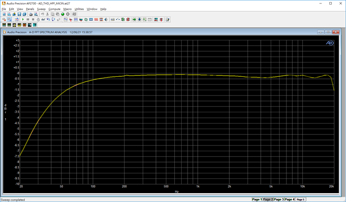
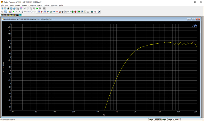
High pass filter
Property name Description Value range hpf-adc1-dmic2ch-level High-pass filtering level < switch value >
switch:
0: not use this level
1: use this level
value: 0~0xfhpf-adc2-dmic2ch-level High-pass filtering level < switch value >
switch:
0: not use this level
1: use this level
value: 0~0xfhpf-dmic4ch-level High-pass filtering level < switch value >
switch:
0: not use this level
1: use this level
value: 0~0xfExample:
hpf-adc1-dmic2ch-level = <1 0xf>;
hpf-adc2-dmic2ch-level = <1 0xf>;
hpf-dmic4ch-level = <1 0x0>;
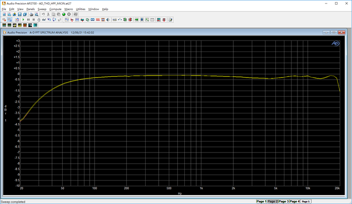
HPF disabled cut-off frequency 20Hz:
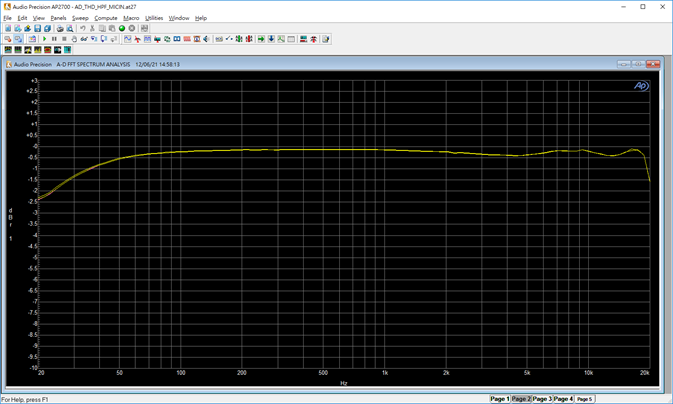
HPF 0x0 cut-off frequency 20Hz:
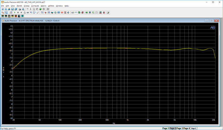
HPF 0x1 cutoff frequency 23Hz:
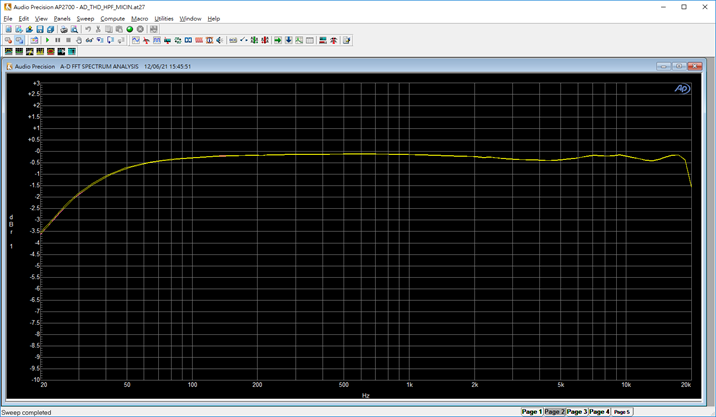
HPF 0x2 cutoff frequency 26Hz:
HPF 0x3 cutoff frequency 32Hz:
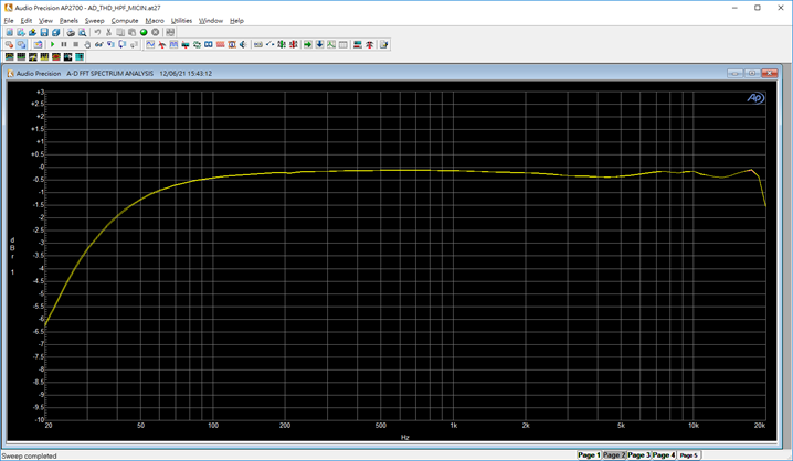
HPF 0x4 cutoff frequency 38Hz:
HPF 0x5 cutoff frequency 52Hz:
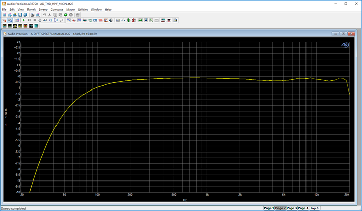
HPF 0x6 cutoff frequency 65Hz:
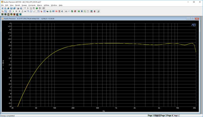
HPF 0x7 cutoff frequency 95Hz:

HPF 0x8 cutoff frequency 140Hz:
HPF 0x9 cutoff frequency 190Hz:
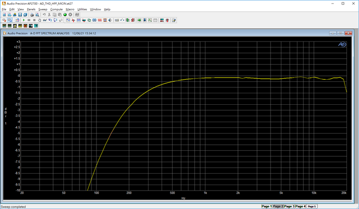
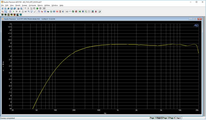
HPF 0xA cut-off frequency 250Hz:

HPF 0xB cut-off frequency 370Hz:
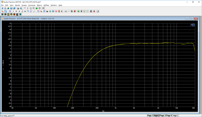
HPF 0xC cut-off frequency 480Hz:
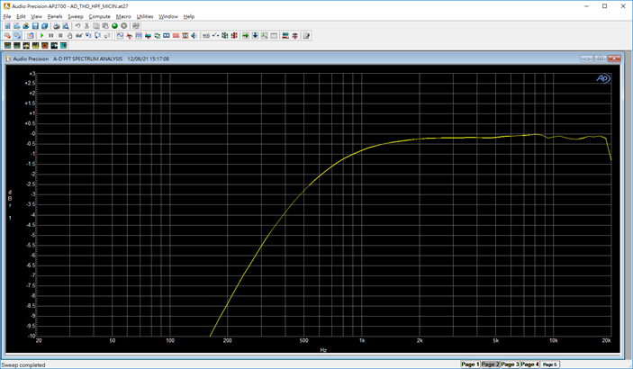
HPF 0xD cut-off frequency 700Hz:
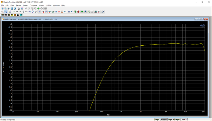
HPF 0xE cut-off frequency 950Hz:
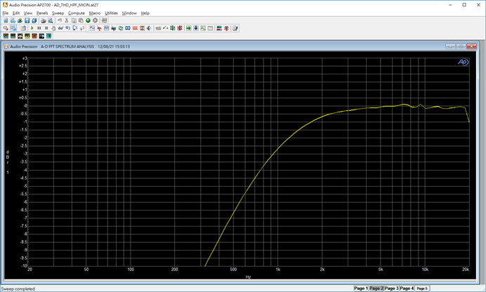
HPF 0xF cut-off frequency 1500Hz:
-
Prevent noise and plosive sound
Property name Description Value range dac_anti_noisy_on Software delay 300ms to prevent noise during playback/ recording 0: OFF
1: ONkeep_adc_power_on ADC power supply is always on 0: OFF
1: ONkeep_dac_power_on DAC power supply always on 0: OFF
1: ON -
dmic bck mode
Property name Description Value range dmic-bck-mode-8k Configure 8K BCK 1~3 dmic-bck-mode-16k Configure 16K BCK 4~7 dmic-bck-mode-32k Configure 32K BCK 8~9 dmic-bck-mode-48k Configure 48K BCK 10~11 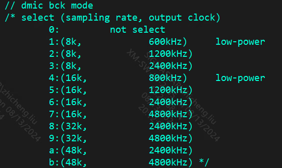
-
Control printing level
Property name Description Value range debug-level Control print level 0x00000001: debug fot test
0x00000002: Print dma LOG information
0x00000004: Print analog part information
0x00000008: Print I2S information
0x00000010: Print DMIC information
0x00000020: Print interrupt information
0x00000040: Print delay
0x00000080: Print attach path information
0x00000100: Print power information
0x00000200: Print Clock information
0x00000400: dump_pcm data
0x00000800 : Print SPDIF informationDynamically adjust reference debug-level
3.3. Audio Channel Control
The system provides audio input and output of ADC, DMIC, ECHO_RX, I2S_RX, DAC, SPDIF_RX, I2S_TX, ECHO_TX and PASSTHROUGH.
The system provides audio output played by aplay, arecord, amixer native alsa framework, and hardware mixing support.
——————————————————————————————————————————————————————————————————————————————————————————————————————
    interface(devide node)      |              CPU DAI                  |           DMA Engine
    ------------------------------------------------------------------------------------------------
                                                DAC
                                                I2S_TX_A
                                                I2S_TX_B             <---       R_DMA_0_Playback
                                                ECHO_TX
                            /
        card_0 - device_0   ---------------------------------------------------------------
                            \       AI_MCH_01_SEL        ADC_A
                                    AI_MCH_23_SEL        ADC_B
                                    AI_MCH_45_SEL        DMIC
                                    AI_MCH_67_SEL   ->   I2S_RX_A    --->       W_DMA_0_Capture
                                    AI_MCH_89_SEL        I2S_RX_B
                                    AI_MCH_AB_SEL        SPDIF_RX
                                    AI_MCH_CD_SEL        ECHO_RX
  /                                 AI_MCH_EF_SEL
-------------------------------------------------------------------------------------------
  \                                             DAC
                                                I2S_TX_A
                                                I2S_TX_B             <---       R_DMA_1_Playback
                                                ECHO_TX
                            /                   SPDIF_TX
        card_1 - device_0   ---------------------------------------------------------------
                            \       AI_MCH_01_SEL        ADC_A
                                    AI_MCH_23_SEL        ADC_B
                                    AI_MCH_45_SEL        DMIC
                                    AI_MCH_67_SEL   ->   I2S_RX_A    --->       W_DMA_1_Capture
                                    AI_MCH_89_SEL        I2S_RX_B
                                    AI_MCH_AB_SEL        SPDIF_RX
                                    AI_MCH_CD_SEL        ECHO_RX
                                    AI_MCH_EF_SEL
——————————————————————————————————————————————————————————————————————————————————————————————————————
The control nodes supported by sound cards 0 and 1, the channel refers to the node named *_SEL
The current input and output channels support playback, capture, passthrough, aec, volume adjust, channel mode and other usage scenarios
console:/ # tinymix -D 0 contents  or    tinymix -D 1 contents
Number of controls: 62
ctl type    num   name                                    value
47  ENUM    1     AI_MCH_01_SEL                           > AI_DETACH, ADC_A, ADC_B, DMIC_01, DMIC_23, DMIC_45, DMIC_67, ECHO_01, I2S_RXA_01, I2S_RXA_23, I2S_RXA_45, I2S_RXA_67, I2S_RXB_01, I2S_RXC_01, SPDIF_RX_01,
48  ENUM    1     AI_MCH_23_SEL                           > AI_DETACH, ADC_A, ADC_B, DMIC_01, DMIC_23, DMIC_45, DMIC_67, ECHO_01, I2S_RXA_01, I2S_RXA_23, I2S_RXA_45, I2S_RXA_67, I2S_RXB_01, I2S_RXC_01, SPDIF_RX_01,
49  ENUM    1     AI_MCH_45_SEL                           > AI_DETACH, ADC_A, ADC_B, DMIC_01, DMIC_23, DMIC_45, DMIC_67, ECHO_01, I2S_RXA_01, I2S_RXA_23, I2S_RXA_45, I2S_RXA_67, I2S_RXB_01, I2S_RXC_01, SPDIF_RX_01,
50  ENUM    1     AI_MCH_67_SEL                           > AI_DETACH, ADC_A, ADC_B, DMIC_01, DMIC_23, DMIC_45, DMIC_67, ECHO_01, I2S_RXA_01, I2S_RXA_23, I2S_RXA_45, I2S_RXA_67, I2S_RXB_01, I2S_RXC_01, SPDIF_RX_01,
51  ENUM    1     AI_MCH_89_SEL                           > AI_DETACH, ADC_A, ADC_B, DMIC_01, DMIC_23, DMIC_45, DMIC_67, ECHO_01, I2S_RXA_01, I2S_RXA_23, I2S_RXA_45, I2S_RXA_67, I2S_RXB_01, I2S_RXC_01, SPDIF_RX_01,
52  ENUM    1     AI_MCH_AB_SEL                           > AI_DETACH, ADC_A, ADC_B, DMIC_01, DMIC_23, DMIC_45, DMIC_67, ECHO_01, I2S_RXA_01, I2S_RXA_23, I2S_RXA_45, I2S_RXA_67, I2S_RXB_01, I2S_RXC_01, SPDIF_RX_01,
53  ENUM    1     AI_MCH_CD_SEL                           > AI_DETACH, ADC_A, ADC_B, DMIC_01, DMIC_23, DMIC_45, DMIC_67, ECHO_01, I2S_RXA_01, I2S_RXA_23, I2S_RXA_45, I2S_RXA_67, I2S_RXB_01, I2S_RXC_01, SPDIF_RX_01,
54  ENUM    1     AI_MCH_EF_SEL                           > AI_DETACH, ADC_A, ADC_B, DMIC_01, DMIC_23, DMIC_45, DMIC_67, ECHO_01, I2S_RXA_01, I2S_RXA_23, I2S_RXA_45, I2S_RXA_67, I2S_RXB_01, I2S_RXC_01, SPDIF_RX_01,
55  ENUM    1     AI_MCH_VIR_SEL                          > AI_DETACH, ADC_A, ADC_B, DMIC_01, DMIC_23, DMIC_45, DMIC_67, ECHO_01, I2S_RXA_01, I2S_RXA_23, I2S_RXA_45, I2S_RXA_67, I2S_RXB_01, I2S_RXC_01, SPDIF_RX_01,
56  ENUM    1     AO_VIR_MUX_SEL                          > VIR_DETACH, DAC, I2S_TXA, I2S_TXB, I2S_TXC, ECHO_0,
57  ENUM    1     DAC_SEL                                 > AO_DETACH, DMA, DMA+SRC,
58  ENUM    1     ECHO_SEL                                > AO_DETACH, DMA, DMA+SRC,
59  ENUM    1     I2S_TXA_SEL                             > AO_DETACH, DMA, DMA+SRC,
60  ENUM    1     I2S_TXB_SEL                             > AO_DETACH, DMA, DMA+SRC,
61  ENUM    1     I2S_TXC_SEL                             > AO_DETACH, DMA, DMA+SRC,
-
Audio Output Device Policy
Supports speaker, SPDIF, I2S_TX device output. Supports switching between devices.
During playback, dynamically adjust the output device process:
  ___________________      ______      __________
|  attach (speaker) | -> | open | -> | playback | -> (start dynamic switching) ->
 ———————————————————      ——————      ——————————

 ___________      ________      _______      _________
|  detach   | -> | attach | -> | close | -> | detach  |
|  (I2S)    |    | (I2S)  |    |       |    | (I2S)   |
 ———————————      ————————      ———————      —————————

(Since different interfaces are attached/detached, there will be audio interruption during the switching process)
In static state, adjust the external device process:
__________ -> | playback | - ________ ______ / —————————— \ _______ ________ | attach | -> | open | -> | close | -> | detach | ———————— —————— \ __________ / ——————— ———————— -> | capture | - —————————— -
Attach channel
-
Connect DAC + I2S outputs individually or simultaneously
Connection operation:
References for tinyalsa usage:
console:/ # tinymix -D 0 set DAC_SEL 1 // R_DMA attach to DAC
console:/ # tinymix -D 0 set I2S_TXA_SEL 1 // R_DMA attach to I2S
alsa-utils usage reference:
console:/ # ./amixer cset name='DAC_SEL' 1
console:/ # ./amixer cset name='I2S_TXA_SEL' 1

Check the status:
console:/ # tinymix -D 0 contents
... ...
57 ENUM 1 DAC_SEL AO_DETACH, > DMA, DMA+SRC,
59 ENUM 1 I2S_TXA_SEL AO_DETACH, > DMA, DMA+SRC,
... ...
-
Multi-channel: AMIC + DMIC input 8-channel data simultaneously
Connection operation: AMIC data is stored in channels 0 and 1, and DMIC data is stored in channels 2, 3, 4, 5, 6, and 7
tinyalsa usage reference:
console:/ # tinymix -D 0 set AI_MCH_01_SEL ADC_A
console:/ # tinymix -D 0 set AI_MCH_23_SEL DMIC_01
console:/ # tinymix -D 0 set AI_MCH_45_SEL DMIC_23
console:/ # tinymix -D 0 set AI_MCH_67_SEL DMIC_45

alsa-utils usage reference:
console:/ # ./amixer cset name='AI_MCH_01_SEL' 'ADC_A'
console:/ # ./amixer cset name='AI_MCH_23_SEL' 'DMIC_01'
console:/ # ./amixer cset name='AI_MCH_45_SEL' 'DMIC_23'
console:/ # ./amixer cset name='AI_MCH_67_SEL' 'DMIC_45'
Note: When capturing data, mono takes channel 0 of multichannel by default.
-
Connect passthrough
Example: ADC to DAC pass-through
Connection operation:
tinyalsa usage reference:
console:/ # tinymix -D 0 set AI_MCH_VIR_SEL 1
console:/ # tinymix -D 0 set AO_VIR_MUX_SEL 1
alsa-utils usage reference:
console:/ # ./amixer cset name='AI_MCH_VIR_SEL' 1
console:/ # ./amixer cset name='AO_VIR_MUX_SEL' 1
-
Connect I2S path
Please configure the master-slave mode of I2S_TX and I2S_RX and the clock signal and other related configurations in the kernel's dtsi file.
Connection operation:
tinyalsa usage reference:
console:/ # tinymix -D 0 set I2S_TXA_SEL 1
alsa-utils usage reference:
console:/ # ./amixer cset name='I2S_TXA_SEL' 1
-
-
Disconnect (detach) the path
To disconnect a channel, just switch the corresponding channel to DETACH state (AI_DETACH / AO_DETACH / VIR_DETACH), for example: detach channel DAC
tinyalsa usage reference:
console:/ # tinymix -D 0 set DAC_SEL 0
alsa-utils usage reference:
console:/ # ./amixer cset name='DAC_SEL' 0
3.4. Headphone Detection
3.4.1. GPIO Detection
-
If a custom machine driver is used, enable the GPIO detection pin and anti-jitter time in DTS:
dummy_codec1: dummy_codec1 { compatible = "sstar,dummy-codec1"; #sound-dai-cells = <0>; headset-det-gpio = <&gpio PAD_SR_PDN1 0>; /* 0:GPIO_ACTIVE_HIGH 1:GPIO_ACTIVE_LOW */ headset-debounce-time = <150>; status = "okay"; }; -
If a simple-card is used, enable simple-audio-card, hp-det-gpio:
i2s_sound2 { compatible = "simple-audio-card"; simple-audio-card,format = "i2s2"; simple-audio-card,name = "sigmastar,i2s2-codec"; simple-audio-card,mclk-fs = <256>; /* 0:GPIO_ACTIVE_HIGH 1:GPIO_ACTIVE_LOW */ simple-audio-card,hp-det-gpio = <&gpio PAD_SR_PDN1 0>; status = "disabled"; simple-audio-card,cpu { sound-dai = <&i2s_bach2>; }; simple-audio-card,codec { sound-dai = <&dummy_codec2>; }; }; -
Input events will be reported when headphones are plugged in
/customer # ./getevent
add device 1: /dev/input/event0
name:     "rtcpwc"
add device 2: /dev/input/event1
name:     "sstar-asoc-card Headset"
could not get driver version for /dev/input/mice, Inappropriate ioctl for device
/dev/input/event1: 0005 0002 00000000
/dev/input/event1: 0000 0000 00000000
/dev/input/event1: 0005 0002 00000001
/dev/input/event1: 0000 0000 00000000
3.4.2. PWM-ADC detection
-
Only supports ADC headset detection in custom machine driver
Field Description (currently supports 3-stage headphone detection):
headset-adc-channel: Read the ADC channel and determine it based on the actual hardware wiring
headset-adc-value-unplug: Voltage range for unplugging headphones
headset-adc-value-headphone: Headphone voltage range
headset-adc-value-headset: Headphone voltage range
headset-adc-poll-time: adc polling time, in ms, default is 1000ms
-
Configuration Example
dummy_codec1: dummy_codec1 {
    compatible = "sstar,dummy-codec1";
    codec-name = "sstar-dummy-codec1";
    #sound-dai-cells = <0>;
    //Pwm-adc-headset
    headset-adc-channel = <4>;
    headset-adc-value-unplug = <1900 2100>;
    headset-adc-value-headphone = <0 200>;
    headset-adc-value-headset = <1300 1500>;
    headset-adc-poll-time = <1000>;
    status = "okay";
};
4. Common debugging methods
4.1. procfs
4.1.1. Confirm whether the sound card is successfully registered
/ # cat  /proc/asound/cards
    0 [sstarasoccard  ]: sstar-asoc-card - sstar-asoc-card
                        sstar-asoc-card
    1 [sstarasoc2card ]: sstar-asoc2-car - sstar-asoc2-card
                        sstar-asoc2-card
/ # ls /dev/snd/
controlC0  controlC1  pcmC0D0c   pcmC0D0p   pcmC1D0c   pcmC1D0p   timer
4.1.2. Confirm I2S TDM status
/ # cat /proc/audio/tdm
TDM RxA
Mck         = <0>
Mode        = <Slave>
Fmt         = <I2S>
WireMode    = <6>
Channel     = <2>
Pgm         = <Off>
Width       = <0>
WckInv      = <Normal>
BckInv      = <Normal>
Short FF    = <0>
ChSwap      = <0 0 0 0>
------------------------------
TDM RxB
Mck         = <0>
Mode        = <Slave>
Fmt         = <I2S>
WireMode    = <6>
Channel     = <2>
Pgm         = <Off>
Width       = <0>
WckInv      = <Normal>
BckInv      = <Normal>
Short FF    = <0>
ChSwap      = <0 0 0 0>
------------------------------
TDM RxC
Mck         = <0>
Mode        = <Slave>
Fmt         = <I2S>
WireMode    = <6>
Channel     = <2>
Pgm         = <Off>
Width       = <0>
WckInv      = <Normal>
BckInv      = <Normal>
Short FF    = <0>
ChSwap      = <0 0 0 0>
------------------------------
TDM TxA
Mck         = <0>
Mode        = <Master>
Fmt         = <I2S>
WireMode    = <6>
Channel     = <2>
Pgm         = <Off>
Width       = <0>
WckInv      = <Normal>
BckInv      = <Normal>
Short FF    = <0>
ChSwap      = <0 0 0 0>
tx active slot = <0xffff>
------------------------------
TDM TxB
Mck         = <0>
Mode        = <Master>
Fmt         = <I2S>
WireMode    = <6>
Channel     = <2>
Pgm         = <Off>
Width       = <0>
WckInv      = <Normal>
BckInv      = <Normal>
Short FF    = <0>
ChSwap      = <0 0 0 0>
tx active slot = <0xffff>
------------------------------
TDM TxC
Mck         = <0>
Mode        = <Master>
Fmt         = <I2S>
WireMode    = <6>
Channel     = <2>
Pgm         = <Off>
Width       = <0>
WckInv      = <Normal>
BckInv      = <Normal>
Short FF    = <0>
ChSwap      = <0 0 0 0>
tx active slot = <0xffff>
------------------------------
4.1.3. Confirm DMA status
/ # cat /proc/audio/dma
Mux Id 1:Src1_Left   2:Src1_Right  3:Src2_Left  4:Src2_Left
Mix Id 1:Src1_1_Left   2:Src1_1_Right  3:Src1_2_Left 4:Src1_2_Right 5:Src2_Left  6:Src2_Left
Mix from Id :0x1:Src1_Left   0x2:Src1_Right  0x4:Src2_Left  0x8:Src2_Right
Mix to Id :0:DAC_A_0  1:DAC_B_0 6:ECHO_A_0 7:ECHO_A_1 8:I2S_TX_A_0 9:I2S_TX_A_1 10:I2S_TX_B_0 11:I2S_TX_B_1 12:SPDIF_TX_A_0 13:SPDIF_TX_A_1

-------------AIO_DMA_AI_A--------------
nWrPos : 0    nActCache : 19041    nSetCache : 0    nLevelCnt : 0
-------------AIO_DMA_AI_B--------------
nWrPos : 0    nActCache : 0    nSetCache : 0    nLevelCnt : 0
-------------AIO_DMA_AO_A--------------
nWrPos : 3603    nLevelCnt : 0
##########Left Path#########
Mix Id : 0
Mux Id : 0
nSrcUse : 0
Mix from : 0
Mix to : 0

#########Right Path#########
Mix Id : 0
Mux Id : 0
nSrcUse : 0
Mix from : 0
Mix to : 0
nDmaSampleRate : 9

-------------AIO_DMA_AO_B--------------
nWrPos : 0    nLevelCnt : 0
##########Left Path#########
Mix Id : 0
Mux Id : 0
nSrcUse : 0
Mix from : 0
Mix to : 0

#########Right Path#########
Mix Id : 0
Mux Id : 0
nSrcUse : 0
Mix from : 0
Mix to : 0
nDmaSampleRate : 0

------------AIO_DMA_AO_DIRECT_A--------
##########Left Path#########
Mix Id : 0
Mux Id : 0
nSrcUse : 0
Mix from : 0
Mix to : 0

#########Right Path#########
Mix Id : 0
Mux Id : 0
nSrcUse : 0
Mix from : 0
Mix to : 0
nDmaSampleRate : 0
4.1.4. Enable sinegen state
-
Check sinegen state
/ # cat /proc/audio/sinegen

[AUDIO Sine Gen]
--------
SineGen ID   = 0
Enable       = 0
Freq         = 0
Gain         = 0
-
Set sinegen
Setting:
    Usage: echo nDma [options] > /proc/audio/sinegen
    nDma    | AI_DMA_A AI_DMA_B AO_DMA_A AO_DMA_B DMIC_A ADC_A ADC_B I2S_RXA I2S_RXB I2S_RXC
    -enable | enable the sinegen 0/1
    -freq   | freq 0~15
    -gain   | gain 0~15

Example:
    echo AO_DMA_A -enable 1 -freq 2 -gain 2 > /proc/audio/sinegen
4.1.5. debug level
-
Check LOG level
/# cat /proc/audio/debug
[AUDIO Debug]
----------------------
Log module       Level
----------------------
test            [Disable]
dma             [Disable]
atop            [Disable]
i2s             [Disable]
dmic            [Disable]
irq             [Disable]
delay           [Disable]
path            [Disable]
power           [Disable]
clock           [Disable]
dump_pcm        [Disable]
spdif           [Disable]
-
Usage
/ # echo > /proc/audio/debug
Usage: echo nModule [options] > /proc/audio/sinegen
    nModule |    test dma atop i2s dmic irq delay path power clock dump_pcm spdif
    -enable |    enable the debug level 0/1
Example:
    echo i2s -enable 1 > /proc/audio/debug
4.1.6. Check the runtime alsa state
-
Check the playback state (taking card0 as an example):
/ # cat /proc/asound/card0/pcm0p/sub0/status state: RUNNING owner_pid : 1120 trigger_time: 991.910025784 tstamp : 999.065843452 delay : 1596 avail : 324 avail_max : 968 ----- hw_ptr : 343480 appl_ptr : 345076 / # cat /proc/asound/card0/pcm0p/sub0/sw_params tstamp_mode: ENABLE period_step: 1 avail_min: 960 start_threshold: 960 stop_threshold: 1920 silence_threshold: 1920 silence_size: 0 boundary: 2013265920 / # cat /proc/asound/card0/pcm0p/sub0/hw_params access: RW_INTERLEAVED format: S16_LE subformat: STD channels: 2 rate: 48000 (48000/1) period_size: 960 buffer_size: 1920 -
Check the capture state (taking card0 as an example):
/ # cat /proc/asound/card0/pcm0c/sub0/status
    state: RUNNING
    owner_pid   : 1129
    trigger_time: 1280.633992485
    tstamp      : 1283.509836152
    delay       : 3520
    avail       : 3520
    avail_max   : 9616
    -----
    hw_ptr      : 138016
    appl_ptr    : 134496

/ # cat /proc/asound/card0/pcm0c/sub0/sw_params
    tstamp_mode: ENABLE
    period_step: 1
    avail_min: 9600
    start_threshold: 1
    stop_threshold: 384000
    silence_threshold: 0
    silence_size: 0
    boundary: 1258291200

/ # cat /proc/asound/card0/pcm0c/sub0/hw_params
    access: RW_INTERLEAVED
    format: S16_LE
    subformat: STD
    channels: 2
    rate: 48000 (48000/1)
    period_size: 9600
    buffer_size: 38400
4.2. Xrun debug
Xrun debug is generally used to debug underrun or overrun. When these two situations occur, the kernel will print a log to assist in locating and analyzing the problem. The following options need to be enabled in Menuconfig:
[*] Advanced Linux Sound Architecture --->
    [*] Debug
        [*] More verbose debug
        [*] Enable PCM ring buffer overrun/underrun debugging0
Then write the corresponding values in the corresponding sound card /proc/asound/card0/pcm0p/xrun_debug. The values are as follows:
#define XRUN_DEBUG_BASIC         (1<<0)
#define XRUN_DEBUG_STACK         (1<<1) /* dump also stack */
#define XRUN_DEBUG_JIFFIESCHECK  (1<<2) /* do jiffies check */
For example, echo 1 > xrun_debug or echo 3 > xrun_debug or echo 7 > xrun_debug enables all debug information detection.
XRUN includes playback's under_run and capture's over_run. When XRUN occurs, the size of each read/write data needs to be changed, usually by increasing it.
For example: use the buffer size mode instead of the period size mode to read and write. For details, please refer to the comments in the read/write example. (In tinyplay and aplay, the default is to write the period size each time)
Note: The period size should be an integer multiple of the sampling rate.
4.3. tiny-alsa
4.3.1. tinypcminfo
Query the sampling rate, format, number of channels, etc. supported by the sound card.
Usage: ./tinypcminfo -D card -d device

PCM out:
      Access:    0x000009
   Format[0]:    0x000004
   Format[1]:    00000000
 Format Name:    S16_LE
   Subformat:    0x000001
        Rate:    min=8000Hz    max=48000Hz
    Channels:    min=1         max=2
 Sample bits:    min=16        max=16
 Period size:    min=8         max=262144
Period count:    min=2         max=40960

PCM in:
      Access:    0x000009
   Format[0]:    0x000004
   Format[1]:    00000000
 Format Name:    S16_LE
   Subformat:    0x000001
        Rate:    min=8000Hz    max=48000Hz
    Channels:    min=1         max=8
 Sample bits:    min=16        max=16
 Period size:    min=2         max=262144
Period count:    min=2         max=4096
4.3.2. tinyplay
Usage: tinyplay file.wav [-D card] [-d device] [-p period_size] [-n n_periods]
Play the test audio file:
tinyplay test.wav -D 0 -d 0 -p 1024 -n 3
Playing sample: 2 ch, 48000 hz , 32 bit
4.3.3. tinycap
Usage: tinycap file.wav [-D card] [-d device] [-c channels] [-r rate] [-b bits] [-p period_size] [-n n_periods]
Record audio at 48k sampling rate:
tinycap test.wav -D 0 -d 0 –c 2 –r 48000 –b 16 –p 1024 –n 3
4.3.4. tinymix
Control the channel switch, volume control, etc. inside the codec. The effect is equivalent to amixer
tinymix
usage: tinymix [options] <command>
options:
    -h, --help               : prints this help message and exits
    -v, --version            : prints this version of tinymix and exits
    -D, --card NUMBER        : specifies the card number of the mixer

commands:
    get NAME|ID              : prints the values of a control
    set NAME|ID VALUE(S) ... : sets the value of a control
        VALUE(S): integers, percents, and relative values
            Integers: 0, 100, -100 ...
            Percents: 0%, 100% ...
            Relative values: 1+, 1-, 1%+, 2%+ ...
    controls                 : lists controls of the mixer
    contents                 : lists controls of the mixer and their contents
4.4. alsa-utils
4.4.1. aplay
Usage: aplay [OPTION]... [FILE]...
-h, --help help
--version print current version
-l, --list-devices list all soundcards and digital audio devices
-L, --list-pcms list device names
-D, --device=NAME select PCM by name
-q, --quiet quiet mode
-t, --file-type TYPE file type (voc, wav, raw or au)
-c, --channels=# channels
-f, --format=FORMAT sample format (case insensitive)
-r, --rate=# sample rate
-d, --duration=# interrupt after # seconds
-s, --samples=# interrupt after # samples per channel
-M, --mmap mmap stream
-N, --nonblock nonblocking mode
-F, --period-time=# distance between interrupts is # microseconds
-B, --buffer-time=# buffer duration is # microseconds
--period-size=# distance between interrupts is # frames
--buffer-size=# buffer duration is # frames
-A, --avail-min=# min available space for wakeup is # microseconds
-R, --start-delay=# delay for automatic PCM start is # microseconds
(relative to buffer size if <= 0)
-T, --stop-delay=# delay for automatic PCM stop is # microseconds from xrun
-v, --verbose show PCM structure and setup (accumulative)
-V, --vumeter=TYPE enable VU meter (TYPE: mono or stereo)
-I, --separate-channels one file for each channel
-i, --interactive allow interactive operation from stdin
-m, --chmap=ch1,ch2,.. Give the channel map to override or follow
--disable-resample disable automatic rate resample
--disable-channels disable automatic channel conversions
--disable-format disable automatic format conversions
--disable-softvol disable software volume control (softvol)
--test-position test ring buffer position
--test-coef=# test coefficient for ring buffer position (default 8)
expression for validation is: coef * (buffer_size / 2)
--test-nowait do not wait for ring buffer - eats whole CPU
--max-file-time=# start another output file when the old file has recorded
for this many seconds
--process-id-file write the process ID here
Example:
./aplay Demo_new.wav
4.4.2. arecord
Usage: arecord [OPTION]... [FILE]...
-h, --help help
--version print current version
-l, --list-devices list all soundcards and digital audio devices
-L, --list-pcms list device names
-D, --device=NAME select PCM by name
-q, --quiet quiet mode
-t, --file-type TYPE file type (voc, wav, raw or au)
-c, --channels=# channels
-f, --format=FORMAT sample format (case insensitive)
-r, --rate=# sample rate
-d, --duration=# interrupt after # seconds
-s, --samples=# interrupt after # samples per channel
-M, --mmap mmap stream
-N, --nonblock nonblocking mode
-F, --period-time=# distance between interrupts is # microseconds
-B, --buffer-time=# buffer duration is # microseconds
--period-size=# distance between interrupts is # frames
--buffer-size=# buffer duration is # frames
-A, --avail-min=# min available space for wakeup is # microseconds
-R, --start-delay=# delay for automatic PCM start is # microseconds
(relative to buffer size if <= 0)
-T, --stop-delay=# delay for automatic PCM stop is # microseconds from xrun
-v, --verbose show PCM structure and setup (accumulative)
-V, --vumeter=TYPE enable VU meter (TYPE: mono or stereo)
-I, --separate-channels one file for each channel
-i, --interactive allow interactive operation from stdin
-m, --chmap=ch1,ch2,.. Give the channel map to override or follow
--disable-resample disable automatic rate resample
--disable-channels disable automatic channel conversions
--disable-format disable automatic format conversions
--disable-softvol disable software volume control (softvol)
--test-position test ring buffer position
--test-coef=# test coefficient for ring buffer position (default 8)
expression for validation is: coef * (buffer_size / 2)
--test-nowait do not wait for ring buffer - eats whole CPU
--max-file-time=# start another output file when the old file has recorded
for this many seconds
--process-id-file write the process ID here
--use-strftime apply the strftime facility to the output file name
--dump-hw-params dump hw_params of the device
--fatal-errors treat all errors as fatal
Example:
./arecord -r 8000 -c 2 -f S16_LE test.wav
4.4.3. amixer
Display reference information for channel configuration/gain configuration:
./ amixer contents
Configure the audio path:
./ amixer sset 'AI_MCH_01_SEL' 'ADC_A'
4.4.4. DMIX
-
Use the -Dplug parameter directly for testing:
./amixer sset DAC_SEL AO_DETACH
./amixer sset DAC_SEL DMA
./aplay -Dplug:dmix --period-size=1024 --buffer-size=2048 -r 48000 -c 2 -f s16_le 48K_16bit_STERO_30s.wav
-
Modify alsa.conf as follows:
pcm.!default { type asym playback.pcm { type plug slave.pcm "dmixer" } capture.pcm { type plug slave { pcm "hw:0,0" } } } pcm.dmixer { type dmix ipc_key 1024 ipc_perm 0666 slave { pcm "hw:0,0" rate 48000 period_time 0 period_size 1024 buffer_size 4096 } bindings { 0 0 # map from 0 to 0 1 1 # map from 1 to 1 } } Test command: ./amixer sset DAC_SEL AO_DETACH ./amixer sset DAC_SEL DMA ./aplay -r 16000 -c 2 -f s16_le 16K_16bit_STEREO_30s_-30db.wav -
Refer to the above alsa.conf, use pipes to test AI and audio mixing:
./tinymix set AI_MCH_01_SEL 0
./tinymix set AI_MCH_01_SEL ADC_A
./ tinymix set 74 0
./ tinymix set 74 DMA
./arecord -D hw:0,0 --period-size=1024 --buffer-size=4096 -r 48000 -c 2 -f s16_le -t raw | ./aplay -r 48000 -c 2 -f s16_le - t raw&
./aplay -r 16000 -c 2 -f s16_le 16K_16bit_STEREO_30s_-30db.wav
4.5. Alsa Native Debug Interface
cat /proc/asound/card0/pcm0p/sub0/status
    state: RUNNING
    owner_pid   : 827
    trigger_time: 3488.618828415
    tstamp      : 3496.126734250
    delay       : 14560
    avail       : 4640
    avail_max   : 10128
    -----
    hw_ptr      : 360380
    appl_ptr    : 374940

cat /proc/asound/card0/pcm0p/sub0/sw_params
    tstamp_mode: ENABLE
    period_step: 1
    avail_min: 9600
    start_threshold: 9600
    stop_threshold: 19200
    silence_threshold: 19200
    silence_size: 0
    boundary: 1258291200

cat /proc/asound/card0/pcm0p/sub0/hw_params
    access: RW_INTERLEAVED
    format: S16_LE
    subformat: STD
    channels: 2
    rate: 48000 (48000/1)
    period_size: 9600
    buffer_size: 19200
4.6. Dump pcm function
If you encounter a problem that you cannot locate, you can turn on the dump_pcm function to check whether the playback/recording data is normal.
-
Usage
echo dump_pcm -enable 1 > /proc/audio/debug
-
Get path (the actual name varies according to parameters such as sampling rate)
/tmp/dump_ai_48000_2ch_16bit.pcm
/tmp/dump_ao_48000_2ch_16bit.pcm
5. Alsa-lib plugin support
5.1. DMIX plugin
-
alsa.conf configuration reference
pcm.!default { type asym playback.pcm { type plug slave.pcm "dmixer" } capture.pcm { type plug slave { pcm "hw:0,0" } } } pcm.dmixer { type dmix ipc_key 1024 ipc_perm 0666 slave { pcm "hw:0,0" rate 48000 period_time 0 period_size 1024 buffer_size 4096 } bindings { 0 0 # map from 0 to 0 1 1 # map from 1 to 1 } } -
Usage reference
./amixer sset DAC_SEL AO_DETACH
./amixer sset DAC_SEL DMA
./aplay -r 16000 -c 2 -f s16_le 16K_16bit_STEREO_30s_-30db.wav
5.2. Alsaloop
- Compile alsaloop app
./amixer  -c 1 cset  name='AI_MCH_01_SEL'   'AI_DETACH'
./amixer  -c 1 cset  name='AI_MCH_01_SEL'   'ADC_A'
./amixer  cset  name='DAC_SEL'   0
./amixer  cset  name='DAC_SEL'   1

./alsaloop -C hw:1,0 -P hw:0,0 -t 5000 -A 3 -S 5 -b -v --period 1024 -f s16_le -r 48000 -c 2
5.3. Dsnoop plugin
-
alsa.conf configuration reference
pcm.!default{ type asym playback.pcm{ type plug slave.pcm "dmixer" } capture.pcm { type plug slave.pcm "dsnooper" } } pcm.dsnooper { type dsnoop ipc_key 10086 ipc_perm 0666 slave { pcm "hw:0,0" rate 48000 channels 2 period_time 0 period_size 1024 buffer_size 4096 } bindings { 0 0 1 1 } } -
Usage reference
./amixer  cset  name='AI_MCH_01_SEL'   'AI_DETACH'
./amixer  cset  name='AI_MCH_01_SEL'   'ADC_A'
./arecord -r 48000 -f S16_LE -d 10 test.wav &
./arecord -r 48000 -f S16_LE -d 10 test2.wav &
6. Reference Examples
The core logic of attach / detach refers to the interface method in alsa-utils:
alsa-utils-1.2.5.1\amixer\amixer.c
static int cset(int argc, char *argv[], int roflag, int keep_handle)
The core logic of attach / detach refers to the following code:
// set control contents for one control
static int aio_control_contents_set_by_name(unsigned int card_id, char *name, char *value)
{
    FUNC_ENTER();
    int                   err      = 0;
    char                  card[64] = "default";
    static snd_ctl_t *    handle   = NULL;
    snd_ctl_elem_info_t * info;
    snd_ctl_elem_id_t *   id;
    snd_ctl_elem_value_t *control;
    snd_ctl_elem_info_alloca(&info);
    snd_ctl_elem_id_alloca(&id);
    snd_ctl_elem_value_alloca(&control);

    if (!name || !value)
    {
        PrintErr("Error param, specify a full control identifier: [name='name']\n");
        return -EINVAL;
    }

    sprintf(card, "hw:%i", card_id);

    if (snd_ctl_ascii_elem_id_parse(id, name))
    {
        PrintErr("Wrong control identifier:(%s)\n", name);
        return -EINVAL;
    }
    if (handle == NULL && (err = snd_ctl_open(&handle, card, 0)) < 0)
    {
        PrintErr("Control(%s) open error:(%s)\n", card, snd_strerror(err));
        return err;
    }
    snd_ctl_elem_info_set_id(info, id);
    if ((err = snd_ctl_elem_info(handle, info)) < 0)
    {
        PrintErr("Cannot find the given element from control(%s)\n", card);
        snd_ctl_close(handle);
        handle = NULL;
        return err;
    }
    snd_ctl_elem_info_get_id(info, id);
    snd_ctl_elem_value_set_id(control, id);
    if ((err = snd_ctl_elem_read(handle, control)) < 0)
    {
        PrintErr("Cannot read the given element from control(%s)\n", card);
        snd_ctl_close(handle);
        handle = NULL;
        return err;
    }
    err = snd_ctl_ascii_value_parse(handle, control, info, value);
    if (err < 0)
    {
        PrintErr("Control(%s) parse error:(%s)\n", card, snd_strerror(err));
        snd_ctl_close(handle);
        handle = NULL;
        return err;
    }
    if ((err = snd_ctl_elem_write(handle, control)) < 0)
    {
        PrintErr("Control(%s) element write error:(%s)\n", card, snd_strerror(err));
        snd_ctl_close(handle);
        handle = NULL;
        return err;
    }

    snd_ctl_close(handle);
    handle = NULL;
    FUNC_EXIT();
    return 0;
}
The logic of open refers to the following code:
static int aio_open(struct ctx *ctx, snd_pcm_stream_t stream, unsigned int card_id, unsigned int device_id, unsigned int channels_param, unsigned int rate_param, unsigned int dma_rate_param)
{
    int  ret      = DEMO_SUCCESS;
    snd_pcm_t **      in_out_pcm;
    if(stream == SND_PCM_STREAM_CAPTURE){
        in_out_pcm = &ctx->in_pcm;
    }
    else {
        in_out_pcm = &ctx->out_pcm;
    }
    snd_pcm_hw_params_t *hw_params;
    snd_pcm_sw_params_t *sw_params;
    snd_output_t *log;
    snd_output_stdio_attach(&log, stderr, 0);
    /* Allocate a hardware parameters object. */
    snd_pcm_hw_params_alloca(&hw_params);
    snd_pcm_sw_params_alloca(&sw_params);
    size_t n;
    int start_delay = 0;
    int stop_delay = 0;
    snd_pcm_uframes_t start_threshold, stop_threshold;

    char card[64] = "default";
    sprintf(card, "hw:%i,%i", card_id, device_id);

    /* Open PCM device for playing (playback). */
    ret = snd_pcm_open(in_out_pcm, card, stream, 0 /*mode*/);
    if (ret < 0)
    {
        PrintErr("Unable to open PCM device (%s)\n", snd_strerror(ret));
        return DEMO_FAIL;
    }

    /* Fill it in with default values. */
    snd_pcm_hw_params_any(*in_out_pcm, hw_params);

#if SSTAR_CUSTOMIZED
    // for dma sample rate
    snd_pcm_hw_params_set_dma_rate(hw_params, dma_rate_param);
#else
    (void)dma_rate_param;
#endif

#if 0
    unsigned int latency = 1000000 * DEFAULT_PERIOD_SIZE / rate_param * DEFAULT_PERIOD_COUNT;
    /* set alsa basic param, only support SND_PCM_FORMAT_S16_LE, SND_PCM_ACCESS_RW_INTERLEAVED */
    ret = snd_pcm_set_params(*in_out_pcm, SND_PCM_FORMAT_S16_LE, SND_PCM_ACCESS_RW_INTERLEAVED, channels_param, rate_param,
                            1 /*soft_resample*/, latency /*in us*/);
    if (ret < 0)
    {
        PrintErr("Unable to set params (%s)\n", snd_strerror(ret));
        return DEMO_FAIL;
    }
#else
    int dir;
    unsigned int channels = channels_param;
    unsigned int rate = rate_param;
    snd_pcm_uframes_t period_frames = DEFAULT_PERIOD_SIZE;
    unsigned int period_count = DEFAULT_PERIOD_COUNT;

    /* Set the desired hardware parameters. */
    /* Interleaved mode */
    snd_pcm_hw_params_set_access(*in_out_pcm, hw_params, SND_PCM_ACCESS_RW_INTERLEAVED);

    /* Signed 16-bit little-endian format */
    snd_pcm_hw_params_set_format(*in_out_pcm, hw_params, SND_PCM_FORMAT_S16_LE);

    /* channels (stereo) */
    snd_pcm_hw_params_set_channels(*in_out_pcm, hw_params, channels);

    /* sampling rate */
    snd_pcm_hw_params_set_rate_near(*in_out_pcm, hw_params, &rate, &dir);

    /* Set period size to frames. */
    snd_pcm_hw_params_set_period_size_near(*in_out_pcm, hw_params, &period_frames, &dir);
    snd_pcm_hw_params_set_periods_near(*in_out_pcm, hw_params, &period_count, &dir);

    /* Write the parameters to the driver */
    ret = snd_pcm_hw_params(*in_out_pcm, hw_params);
    if (ret < 0) {
        PrintErr("unable to set hw parameters (%s)\n", snd_strerror(ret));
        return DEMO_FAIL;
    }
#endif

    ret = snd_pcm_sw_params_current(*in_out_pcm, sw_params);
    if (ret < 0) {
        PrintErr("Unable to get current sw params.");
        return DEMO_FAIL;
    }

    if(stream == SND_PCM_STREAM_CAPTURE){
        start_delay = 1;
    }
    /* round up to closest transfer boundary */
    n = DEFAULT_PERIOD_SIZE * DEFAULT_PERIOD_COUNT;
    if (start_delay <= 0) {
        start_threshold = n + (double) rate_param * start_delay / 1000000;
    } else{
        start_threshold = (double) rate_param * start_delay / 1000000;
    }
    if (start_threshold < 1){
        start_threshold = 1;
    }
    if (start_threshold > n){
        start_threshold = n;
    }
    snd_pcm_sw_params_set_start_threshold(*in_out_pcm, sw_params, start_threshold);

    if (stop_delay <= 0) {
        stop_threshold = n + (double) rate_param * stop_delay / 1000000;
    }
    else {
        stop_threshold = (double) rate_param * stop_delay / 1000000;
    }
    snd_pcm_sw_params_set_stop_threshold(*in_out_pcm, sw_params, stop_threshold);

    if (snd_pcm_sw_params(*in_out_pcm, sw_params) < 0) {
        snd_pcm_sw_params_dump(sw_params, log);
        PrintErr("Unable to get current sw params.");
        return DEMO_FAIL;
    }

    // for dump info
    PrintInfo("===hw_params_dump====\n");
    snd_pcm_hw_params_dump(hw_params, log);
    PrintInfo("=====================\n");

    PrintInfo("===sw_params_dump====\n");
    snd_pcm_sw_params_dump(sw_params, log);
    PrintInfo("=====================\n");

    PrintInfo("===pcm_dump==========\n");
    snd_pcm_dump(*in_out_pcm, log);
    PrintInfo("=====================\n");

    snd_output_close(log);

    FUNC_EXIT();
    return ret;
}
The logic of close refers to the following code:
snd_pcm_close(ctx->in_pcm);
snd_pcm_close(ctx->out_pcm);
The logic of read refers to the following code:
static int sample_capture(struct ctx *ctx)
{
    FUNC_ENTER();
    int    ret = DEMO_SUCCESS;
    int rc;
    char *buffer;
    unsigned int size;
    unsigned int total_frames_read;
    unsigned int bytes_per_frame;
    // Read data of buffer size each time
    snd_pcm_uframes_t frames = snd_pcm_bytes_to_frames(ctx->in_pcm, DEFAULT_PERIOD_SIZE * DEFAULT_PERIOD_COUNT);
    // Read data of period size each time
    //snd_pcm_uframes_t frames = snd_pcm_bytes_to_frames(ctx->in_pcm, DEFAULT_PERIOD_SIZE);

    size = snd_pcm_frames_to_bytes(ctx->in_pcm, frames);
    buffer = malloc(size);
    if (!buffer) {
        PrintErr("unable to allocate %zu bytes\n", size);
        return -1;
    }

    bytes_per_frame = snd_pcm_frames_to_bytes(ctx->in_pcm, 1);
    total_frames_read = 0;

    /* catch ctrl-c to shutdown cleanly */
    signal(SIGINT, stream_close);

    while (!close_flag) {
        if (ctx->in_pcm) {
            rc = snd_pcm_readi(ctx->in_pcm, (void*)buffer, frames);
            if (rc == -EPIPE) {
                /* EPIPE means overrun */
                PrintErr("overrun occurred\n");
                snd_pcm_prepare(ctx->in_pcm);
            } else if (rc < 0) {
                PrintErr("error from read: %s\n", snd_strerror(rc));
                break;
            } else if (rc != (int)frames) {
                PrintErr("short read, read %d frames\n", rc);
            } else {
                total_frames_read += frames;
                if (fwrite(buffer, bytes_per_frame, frames, ctx->in_file) != frames) {
                    PrintErr("Error capturing sample\n");
                    break;
                }
                PrintInfo("total_read data(%u), read frames(%u) \n", total_frames_read, frames);
            }
        } else {
            PrintErr("pcm null.\n");
            ret = E_ERR_NOT_INIT;
            break;
        }
    }

    free(buffer);
    FUNC_EXIT();
    return 0;
}
The logic of write refers to the following code:
static int sample_playback(struct ctx *ctx)
{
    FUNC_ENTER();
    int    ret = DEMO_SUCCESS;
    char * buffer;
    size_t buffer_size         = 0;
    size_t num_read            = 0;
    size_t remaining_data_size = ctx->chunk_header.sz;
    size_t played_data_size    = 0;
    size_t read_size           = 0;

    // frames to bytes
    // Read data of buffer size each time
    buffer_size = snd_pcm_frames_to_bytes(ctx->out_pcm, DEFAULT_PERIOD_SIZE*DEFAULT_PERIOD_COUNT);
    // Read data of period size each time
    // buffer_size = snd_pcm_frames_to_bytes(ctx->out_pcm, DEFAULT_PERIOD_SIZE);
    buffer      = (char *)malloc(buffer_size);
    if (!buffer)
    {
        PrintErr("unable to allocate %zu bytes\n", buffer_size);
        return -1;
    }

    /* catch ctrl-c to shutdown cleanly */
    signal(SIGINT, stream_close);

    PrintInfo("data size(%u), buffer_size(%u)\n", remaining_data_size, buffer_size);
    do
    {
        memset(buffer, 0, sizeof(buffer));
        read_size                = remaining_data_size > buffer_size ? buffer_size : remaining_data_size;
        num_read                 = fread(buffer, 1, read_size, ctx->out_file);
        snd_pcm_uframes_t frames = snd_pcm_bytes_to_frames(ctx->out_pcm, num_read);
        PrintInfo("remaining data size(%u), write frames(%u) \n", remaining_data_size, frames);
        if (num_read > 0)
        {
            if (ctx->out_pcm)
            {
                int ret = snd_pcm_writei(ctx->out_pcm, (void *)buffer, frames);
                if (ret == -EPIPE)
                {
                    PrintErr("underrun occured\n");
                }
                else if (ret < 0)
                {
                    PrintErr("error from writei (%d:%s)\n", ret, snd_strerror(ret));
                    break;
                }
            }
            else
            {
                PrintErr("pcm null.\n");
                break;
            }

            remaining_data_size -= num_read;
            played_data_size += snd_pcm_frames_to_bytes(ctx->out_pcm, frames);
        }
    } while (!close_flag && num_read > 0 && remaining_data_size > 0);

    free(buffer);
    PrintInfo("Played (%zu) bytes. Remains (%zu) bytes.\n", played_data_size, remaining_data_size);

    FUNC_EXIT();
    return 0;
}
7. FAQ
7.1. Sound card registration failed
-
Check if the sound card is registered successfully:
cat /proc/asound/cards
-
Locate the cause based on kmsg: For example, the following log indicates that the sound card instantiation failed
asoc-simple-card soc:asoc_sound: ASoC: failed to instantiate card -110
-
CODEC fail
Use a multimeter and oscilloscope to measure CODEC voltage and clock; cooperate with i2c_read_write to confirm whether the i2c device communication is normal
7.2. Playing Silence
-
Make sure the audio source is a non-silent file
-
Use aplay or tinyplay to play the video and determine whether the problem occurs in user mode or kernel mode
-
Wait for more than 10 seconds to confirm whether it is an I/O error.
-
Confirm whether there is an attached path first. The following LOG indicates that the path is not attached:
[ALSA ERROR][mhal_audio_ao_start][3915]: enAoDma[0] bIsAttached FALSE
-
Use amixer or tinymix to check if the CODEC internal DAC path is open and the volume is muted
-
Check the register configuration and confirm whether the configuration is correct with the chip manual or CODEC manual: IOMUX, DAI, CODEC.
-
Use a multimeter and oscilloscope to measure voltage, clock, and data. Confirm that the voltage and clock are normal and there is a waveform on the data line; measure whether the CODEC near-end analog output signal is normal, measure the PA enable gpio level, and locate the problem point step by step
7.3. Playback Distortion
-
Use aplay or tinyplay to play 1KHz 0db audio files
-
Use an oscilloscope to measure whether the analog output sine wave is normal and whether there is clipping distortion
-
Adjust the digital or analog gain, observe the waveform at the output of the CODEC chip, and compare the index test data to see if they match
-
Check each level for nodes that introduce distortion
7.4. Recording Silence
-
CODEC end generates 1KHz 0db waveform input through signal generator
-
Use arecord or tinycap to record and determine whether the problem occurs in user mode or kernel mode
-
Wait for more than 10 seconds to confirm whether it is an I/O error.
-
Use amixer or tinymix to check if the CODEC internal ADC path is open and the volume is muted
-
Check the register configuration and confirm whether the configuration is correct with the chip manual or CODEC manual: IOMUX, DAI, CODEC.
-
Use a multimeter and oscilloscope to measure voltage, clock and data. Confirm that the voltage and clock are normal and there is a waveform on the data line
-
Check whether the CODEC near-end analog input signal is normal and locate the problem point step by step
7.5. Recording Distortion
- CODEC end generates 1KHz 0db waveform input through signal generator
- Record with arecord or tincap, output via loopback, measure with an oscilloscope, or analyze with PC tools
- Adjust digital or analog gain, observe loopback waveform, and compare the index test data to see if they match
- Check each level for nodes that introduce distortion
7.6. Too Fast or Too Slow
- Check the clk summary to confirm whether the clock (MCLK, BCLK, LRCK) is accurate
- Use an oscilloscope to confirm that the clock signal is accurate
- Use PC tools to record the output signal and confirm whether the data is lost or increased through waveform or spectrum analysis
- Use a logic analyzer to dump the chip output data to confirm whether the data is lost or added
7.7. Regular Staccato
- Regular staccato problems usually occur in heterogeneous systems, such as: UAC application scenarios, BT voice application scenarios, network audio streaming, etc.
- The root cause is that the clock is asynchronous and the error accumulates over time. This type of problem can be solved by audio clock compensation.
- Abnormal buffer boundary processing can also cause regular staccato and noise. You can use xrun to analyze the problem.
- Turn on the dump_pcm function and dump the audio file to analyze if there is any abnormality
7.8. Noise
- Check whether the clock signal is accurate and whether the jitter is too large.
- Check if there are glitches on the clock, especially within the edge valid value judgment range voltage.
- Confirm the CODEC power supply and ground conditions. CODEC is sensitive to power supply noise. Any noise coupled into the power supply or ground will cause CODEC performance to degrade, the background noise to increase, and the occurrence of noise.
- Hardware uses differential circuits to suppress common mode noise.
- Check the hardware PCB layout and identify the source of noise.