Sensor_Porting
REVISION HISTORY
| Revision No. | Description |
Date |
|---|---|---|
| 1.0 | 04/17/2025 |
1. Environmental Preparation
Before starting porting, please make sure that the sensor wiring is correct. For MIPI sensor wiring, please refer to this document SENSOR USER GUIDE. The basic principles are the same on different CHIPs.
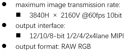
First, you need to confirm the requirements, including the sensor's resolution, frame rate, pixel width, number of MIPI Lanes, and mclk frequency, give the requirements to the manufacturer, and ask them to provide a data sheet and initialization table.
1.1 Sensor Initialize table
init table is a set of I2C configurations. After being written to the sensor through I2C, the data is output according to the established target.
I2C A16D8 init table
......
0x3280,0x00,
0x3281,0x00,
0x3301,0x3c,
0x3304,0x30,
0x3306,0xe8,
0x3308,0x10,
0x3309,0x70,
0x330a,0x01,
0x330b,0xe0,
0x330d,0x10,
0x3314,0x92,
0x331e,0x29,
......
2. Sensor Driver Porting
2.1 Sensor Driver Basic Parameters
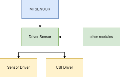
The sensor driver is actually managed by the sensor interface module. Register means providing sensor information to the sensor interface, including but not limited to the basic image parameters of the sensor, data interface parameters, control interface parameters, how to power on and off, output streams, modify FPS , etc. These require the sensor driver to fill in the structure or implement some corresponding callback functions and register them to the sensor interface module.
2.1.1 Sensor module register
In Linux, each Sensordriver is a separate module. The SDK implements two macros to compile the driver into a Linux module and register the driver to the sensor interface.
| MACRO | SENSOR_DRV_ENTRY_IMPL_BEGIN_EX( Name ) | ||||
|---|---|---|---|---|---|
| Description | This macro defines the module parameters required for the Sensor to register with the Sensor Interface and is usually placed in the driver source file header. | ||||
| Parameters |
|
||||
| Return |
| MACRO | SENSOR_DRV_ENTRY_IMPL_END_EX( Name, LinearEntry, HdrSefEntry, HdrLefEntry, PrivateDataType ) | ||||||||||||||||||||
|---|---|---|---|---|---|---|---|---|---|---|---|---|---|---|---|---|---|---|---|---|---|
| Description | This macro defines the module parameters required for the Sensor to register with the Sensor Interface and is usually placed at the end of the driver source file | ||||||||||||||||||||
| Parameters |
|
||||||||||||||||||||
| Return |
- The Name used in the two macros remains the same
2.1.2 Basic Sensor Image Parameters
The basic outflow needs to implement the LinearEntry handle for registration, which basically constructs the ss_cus_sensor structure. The key parts of the data structure prototype are as follows:
/* Location : sdk\driver\SensorDriver\drv\pub\drv_ss_cus_sensor.h */

typedef struct __ss_cus_sensor{

.......

char strSensorStreamName[32];        /**< Please fill the sensor modle id string here then libcamera user can read model_id by using cameraGetSensorModelID() */
.*/

// i2c
app_i2c_cfg i2c_cfg;                 /**< Sensor i2c setting */

// sensor data enum list*/
CUS_SEN_BAYER           bayer_id;    /** < Sensor bayer raw pixel order */
CUS_SEN_RGBIR           RGBIR_id;    /** < Sensor bayer raw pixel order */
CUS_SENIF_BUS           sif_bus;     /** < Select sensor interface */
CUS_DATAPRECISION       data_prec;   /** < Raw data bits */

cus_camsensor_res_list  video_res_supported; /** < Resolution list */
InterfaceAttr_u         interface_attr;

//sensor calibration
int           mclk;        /** < Sensor master clock frequency */

......

}ss_cus_sensor;
Basic sensor image parameters that need to be configured
| Param | Type | value | desc |
|---|---|---|---|
| model_id | char[31] | string | Sensor name, any string |
| bayer_id | enum | CUS_BAYER_RG CUS_BAYER_GR CUS_BAYER_BG CUS_BAYER_GB |
Sensor bayer arrangement format |
| sif_bus | enum | CUS_SENIF_BUS_PARL CUS_SENIF_BUS_MIPI CUS_SENIF_BUS_BT601 CUS_SENIF_BUS_BT656 CUS_SENIF_BUS_BT1120 CUS_SENIF_BUS_LVDS |
Sensor data interface type |
| data_prec | enum | CUS_DATAPRECISION_8 CUS_DATAPRECISION_10 CUS_DATAPRECISION_16 CUS_DATAPRECISION_12 CUS_DATAPRECISION_14 |
pixel width port:8b/10b/12b/14b/16b |
Take a certain sensor model as an example
These parameters are flexible and need to be determined based on actual needs and the init table configuration obtained from the Sensor vendor.
2.1.3 Power on and off parameters
The following parameters are required to control the power on and off of the Sensor:
| Param | Type | value | desc |
|---|---|---|---|
| mclk | enum | CUS_CMU_CLK_27MHZ CUS_CMU_CLK_21P6MHZ CUS_CMU_CLK_21P6MHZ CUS_CMU_CLK_12MHZ CUS_CMU_CLK_5P4MHZ CUS_CMU_CLK_36MHZ CUS_CMU_CLK_54MHZ CUS_CMU_CLK_43P2MHZ CUS_CMU_CLK_61P7MHZ CUS_CMU_CLK_72MHZ CUS_CMU_CLK_48MHZ CUS_CMU_CLK_24MHZ |
mclk frequency, select according to Sensor requirements, different chips may have some differences, please refer toSENSOR USER GUIDE 3. FUNCTIONAL DESCRIPTION |
-
MCLK is the working clock provided by the SoC to the sensor. For the sensor, it may be called INCK/EXTCLK in the sensor data sheet, which is easy to confuse and needs to be carefully identified.
-
pwdn and reset are actually used to control the high and low levels of two GPIOs, but not all sensors require two pins to control power on and off. Some sensors only need one pin to achieve power-on operation.
Take a certain sensor model as an example
-
Confirm which SOC and which PAD XSHUTDN is connected to, whether it is pwdn or rst
-
Set the corresponding pin to trigger level
2.1.4 I2C Interface Parameters
Most sensors are controlled by I2C or I2C-compatible interfaces. The parameters of the I2C interface are defined by the structure app_i2c_cfg.
/*  sdk\driver\SensorDriver\drv\pub\drv_ss_cus_sensor.h */
typedef struct _app_i2c_cfg{
    ISP_I2C_MODE        mode;   //!< I2C_NORMAL_MODE only
    ISP_I2C_FMT         fmt;        //!< I2C data format
    u32                 speed;          //!< I2C clock in Hz
    u16                 address;       //!< Sensor slave address , bit[7~1] are available, bit[0] user don't care
    u16  reserved;
}__attribute__((packed, aligned(1))) app_i2c_cfg;
| Param | Type | value | desc |
|---|---|---|---|
| mode | enum | I2C_LEGACY_MODE I2C_NORMAL_MODE |
Only use I2C_NORMAL_MODE |
| fmt | enum | I2C_FMT_A8D8 I2C_FMT_A16D8 I2C_FMT_A8D16 I2C_FMT_A16D16 |
I2C data format, select according to Sensor requirements I2C_FMT_AxDy: x bit Address, y bit Data |
| speed | uint | 60000~320000 | I2C communication rate, unit (Hz) |
| address | uint | 0x00~0xFF | Sensor I2Caddress, 8bit addressing address, read and write bits can be 0/1 |
Take the information provided in the following figure as an example
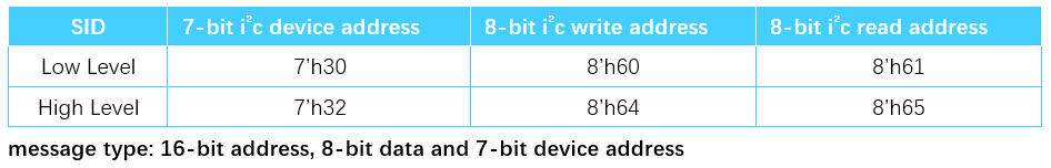
-
fmt: I2C_FMT_A16D8
-
speed: Consult the sensor vendor for recommended values
-
address: 0x60/0x61
2.1.5 Data interface parameters
The information of the data interface is mainly defined by the InterfaceAttr_u union. The union is used to be compatible with different interface types. Here we only look at the MIPI interface.
/*  sdk\driver\SensorDriver\drv\pub\drv_ss_cus_sensor.h */
typedef union {
......
    //MIPI sensor
    struct {
        u8 mipi_lane_num;
        CUS_SEN_INPUT_FORMAT mipi_data_format;      /**< 0: YUV 422 format. 1: RGB pattern. */
        CUS_SENSOR_YUV_ORDER mipi_yuv_order;        /**< YUYV or UYVY*/
        CUS_HDR_MODE mipi_hdr_mode;
        CUS_HDR_FUSION_TYPE mipi_hdr_fusion_type;
        u8 mipi_hdr_virtual_channel_num;
        u32 mipi_user_def;
    } attr_mipi;
......
}  InterfaceAttr_u;
| Param | Type | value | desc |
|---|---|---|---|
| mipi_lane_num | uint | 1 / 2 / 4 | Number of Data Lanes output by the Sensor |
| mipi_data_format | enum | CUS_SEN_INPUT_FORMAT_YUV422 CUS_SEN_INPUT_FORMAT_RGB |
Select YUV or RGB according to the format YUV422: only supports YUV4228b RGB: supports RAW8/10/12/14/16 |
| mipi_yuv_order | enum | CUS_SENSOR_YUV_ORDER_CY CUS_SENSOR_YUV_ORDER_YC |
YUV arrangement |
| mipi_hdr_mode | enum | CUS_HDR_MODE_NONE CUS_HDR_MODE_SONY_DOL CUS_HDR_MODE_DCG CUS_HDR_MODE_COMP_VS CUS_HDR_MODE_VC CUS_HDR_MODE_VC ..... |
HDR type Linear mode select NONE |
| mipi_hdr_virtual_channel_num | uint | 0 / 1 / 2 / 3 | CSI channel number, Linear mode writes 0, HDR will use other channels |
example:
handle->interface_attr.attr_mipi.mipi_lane_num = 4;
handle->interface_attr.attr_mipi.mipi_data_format = CUS_SEN_INPUT_FORMAT_RGB;
handle->interface_attr.attr_mipi.mipi_hdr_mode = CUS_HDR_MODE_VC; //hdr type setting
handle->interface_attr.attr_mipi.mipi_hdr_virtual_channel_num = 1; //virtual chnannel can be 0~3
- note: This structure does not require initialization for alternate interface sensors (e.g., DVP or BT656).
2.1.6 Resolution Information
The list of all resolution information supported by Sensor is defined by cus_camsensor_res_list and cus_camsensor_res. The structure prototype is as follows:
/*  sdk\driver\SensorDriver\drv\pub\drv_ss_cus_sensor.h */
typedef struct _cus_camsensor_res_list
{
    u32 num_res;                            /**< number of sensor resolution in list */
    u32 ulcur_res;                          /**< current sensor resolution index */
    cus_camsensor_res res[31];              /**< resolution list max size is 31 */
} __attribute__((packed, aligned(4))) cus_camsensor_res_list;

typedef struct _cus_camsensor_res{
    u16 u16width;          /**< Image crop width */
    u16 u16height;         /**< Image crop height */
    u16 u16max_fps;        /**< Max fps in this resolution */
    u16 u16min_fps;        /**< Min fps in this resolution*/
    u16 u16crop_start_x;   /**< Image crop width start position*/
    u16 u16crop_start_y;   /**< Image crop height start position*/
    u16 u16OutputWidth;   /**< Sensor actual output width */
    u16 u16OutputHeight;  /**< Sensor actual output height */
    u16 u16MinFrameLengthLine;    // in Line
    u16 u16RowTime;
    char strResDesc[32];
} __attribute__((packed, aligned(4))) cus_camsensor_res;
2.1.7 AE INFO
The structure prototype in Sensor Driver used to read and write AE info is as follows:
typedef struct
{
    u8 u8AEGainDelay;                /**< How many frame delay from writing AE gain to take effect*/
    u8 u8AEShutterDelay;             /**< How many frame delay from writing AE shutter to take effect*/
    u8 u8AEGainCtrlNum;              /**HDR gain share or not,1:share 2:separate*/
    u8 u8AEShutterCtrlNum;           /**HDR shutter share or not,1:share 2:separate*/
    u32 u32PixelSize;                /**in nano meter*/
    u32 u32AEShutter_length;         /**< struct size */
    u32 u32AEShutter_max;            /**< maximun shutter in us*/
    u32 u32AEShutter_min;            /**< minimum shutter in us*/
    u32 u32AEShutter_step;           /**< shutter in step us*/
    u32 u32AEGain_max;
    u32 u32AEGain_min;
} __attribute__((packed, aligned(4))) CUS_SENSOR_AE_INFO_t;
2.2 Sensor Stream on
From the API of the MI SENSOR layer, the typical Sensor outflow calling process is as follows:
->MI_SNR_SetPlaneMode //Set HDR mode
->MI_SNR_SetRes //Select resolution
->MI_SNR_Enable //Enable sensor outflow
In this process, the interfaces registered by the Sensor Driver to the Sensor Interface are called. These interfaces need to be implemented as callbacks. The callback interfaces are also defined in the structure of ss_cus_sensor. The key interface prototypes required for outflow are as follows
/*  sdk\driver\SensorDriver\drv\pub\drv_ss_cus_sensor.h */
typedef struct __ss_cus_sensor{
......
int (*pCus_sensor_poweron)(struct __ss_cus_sensor* handle, u32 idx);
int (*pCus_sensor_poweroff)(struct __ss_cus_sensor* handle, u32 idx);
int (*pCus_sensor_GetVideoResNum)(struct __ss_cus_sensor* handle, u32 *ulres_num);
int (*pCus_sensor_SetVideoRes)(struct __ss_cus_sensor* handle, u32 res_id);
int (*pCus_sensor_GetCurVideoRes)(struct __ss_cus_sensor* handle, u32 *cur_idx, cus_camsensor_res **res);
int (*pCus_sensor_GetVideoRes)(struct __ss_cus_sensor* handle, u32 res_idx, cus_camsensor_res **res);
int (*pCus_sensor_init)(struct __ss_cus_sensor* handle);
int (*pCus_sensor_release)(struct __ss_cus_sensor* handle);
......
}ss_cus_sensor;
2.2.1 Power ON/OFF
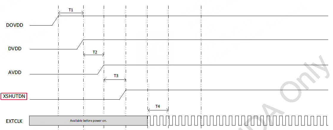
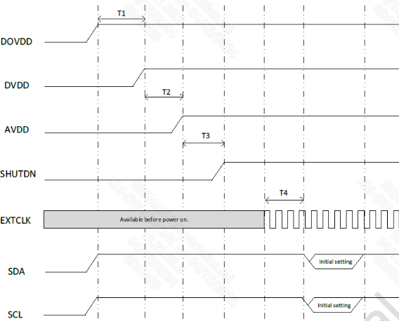
To implement Power on/off, porting is required for each sensor datasheet’s power-on and power-off timing diagram.
Take a certain sensor model as an example

In addition to the power-on sequence, some additional I/O and clock operations are required. The APIs for these operations are provided by the Sensor Interface. The interface prototypes used are as follows:
/*  sdk\driver\SensorDriver\drv\pub\drv_ss_cus_sensor.h */
typedef struct __ISensorIfAPI {
......
    int (*PowerOff)(u32 idx, CUS_CLK_POL pol);
    int (*Reset)(u32 idx, CUS_CLK_POL pol);
    int (*MCLK)(u32 idx, u8 bONOFF, CUS_MCLK_FREQ mclk);
    int (*SetIOPad)(u32 idx, CUS_SENIF_BUS ulSnrType, u32 ulSnrPadCfg);
    int (*SetCSI_Clk)(u32 idx, CUS_CSI_CLK clk);
    int (*SetCSI_Lane)(u32 idx, u16 num_lan, u8 bon_off);
    int (*SetCSI_LongPacketType)(u32 idx, u16 ctl_cfg0_15, u16 ctl_cfg16_31, u16 ctl_cfg32_47);
......
}ISensorIfAPI;
-
PowerOff: control power down pin voltage
Param Type value desc idx unsigned int unsigned int sensor pad id pol enum CUS_CLK_POL_POS CUS_CLK_POL_NEG CUS_CLK_POL_POS: active high CUS_CLK_POL_NEG: low active example:
sensor_if->PowerOff(idx,CUS_CLK_POL_POS); // pull pdn pin high
-
Reset: control reset pin voltage
Param Type value desc idx unsigned int unsigned int sensor pad id pol enum CUS_CLK_POL_POS CUS_CLK_POL_NEG CUS_CLK_POL_POS: active high CUS_CLK_POL_NEG: low active example:
sensor_if->Reset(idx, CUS_CLK_POL_NEG); // pull rst pin high
-
MCLK: config sensor mclk
Param Type value desc idx unsigned int unsigned int sensor pad id bONOFF unsigned char unsigned char greater than 0 means enable mclk enum CUS_CMU_CLK_27MHZCUS_CMU_CLK_21P6MHZCUS_CMU_CLK_12MHZCUS_CMU_CLK_5P4MHZCUS_CMU_CLK_36MHZCUS_CMU_CLK_54MHZCUS_CMU_CLK_43P2MHZCUS_CMU_CLK_61P7MHZCUS_CMU_CLK_72MHZCUS_CMU_CLK_48MHZCUS_CMU_CLK_24MHZCUS_CMU_CLK_37P125MHZCUS_CMU_CLK_LPLL_DIV1CUS_CMU_CLK_LPLL_DIV2CUS_CMU_CLK_LPLL_DIV4CUS_CMU_CLK_LPLL_DIV8 choose mclk frequency example:
sensor_if->MCLK(idx, 1, CUS_CMU_CLK_27MHZ); // set MCLK ot 27M and enable
-
SetIOPad: config sensor padmux mode
Param Type value desc idx unsigned int unsigned int sensor pad id ulSnrType enum CUS_SENIF_BUS_PARLCUS_SENIF_BUS_MIPICUS_SENIF_BUS_BT601CUS_SENIF_BUS_BT656CUS_SENIF_BUS_BT1120CUS_SENIF_BUS_LVDSCUS_SENIF_BUS_MAX sensor interface type ulSnrPadCfg unsigned int unsigned int mipi lane number example:
sensor_if->SetIOPad(idx, CUS_SENIF_BUS_MIPI, 4); //config sensor to MIPI mode with 4 pairs data lane
-
SetCSI_Clk: config MIPI RX MAC CLK
Param Type value desc idx unsigned int unsigned int sensor pad id clk enum CUS_CSI_CLK_DISABLECUS_CSI_CLK_432MCUS_CSI_CLK_384MCUS_CSI_CLK_320MCUS_CSI_CLK_288MCUS_CSI_CLK_240MCUS_CSI_CLK_216MCUS_CSI_CLK_172MCUS_CSI_CLK_144M MIPI RX MAC clk frequency, The selected clock (CLK) must satisfy the following relationship: MAC CLK > MIPI Data Rate(unit:bps)/8x1.5 example:
sensor_if->SetCSI_Clk(idx, CUS_CSI_CLK_288M);// set MIPI RX MAC CLk to 288M
-
SetCSI_Lane: config MIPI RX Data Lane number
Param Type value desc idx unsigned int unsigned int sensor pad id num_lan unsigned short unsigned short data lane number bon_off unsigned char unsigned char enable or not example:
sensor_if->SetCSI_Lane(idx, 4, 1); // 4 pairs Data Lane
-
SetCSI_LongPacketType: config MIPI long packet data type
Param Type value desc idx unsigned int unsigned int sensor pad id ctl_cfg0_15 unsigned short unsigned short long packet data type[0:15] ctl_cfg16_31 unsigned short unsigned short long packet data type[16:31] ctl_cfg32_47 unsigned short unsigned short long packet data type[32:47] The supported data type are shown in the figure below. Multiple bits can be selected simultaneously.
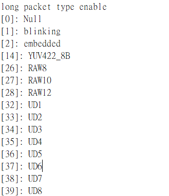
example:
sensor_if->SetCSI_LongPacketType(idx, 0, 0x1C00, 0);// [26:28] receive raw8/raw10/raw12
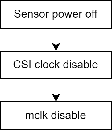
Typical power-on flow
-
MIPI sensor
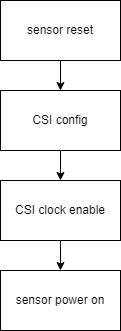
Sample Code
static int pCus_poweron(ss_cus_sensor *handle, u32 idx) { ISensorIfAPI *sensor_if = handle->sensor_if_api; SENSOR_DMSG("[%s] ", __FUNCTION__); //Sensor Disable sensor_if->PowerOff(idx, CUS_CLK_POL_NEG); // Pull the power down pin to an invalid level sensor_if->Reset(idx, CUS_CLK_POL_NEG); // Pull the reset pin to an invalid level SENSOR_USLEEP(1000); // MIPI CSI config sensor_if->SetIOPad(idx, handle->sif_bus, handle->interface_attr.attr_mipi.mipi_lane_num); // Interface I/O configuration sensor_if->SetCSI_Clk(idx, CUS_CSI_CLK_288M); // CSI clock frequency configuration sensor_if->SetCSI_Lane(idx, handle->interface_attr.attr_mipi.mipi_lane_num, 1); // CSI Lane quantity configuration sensor_if->SetCSI_LongPacketType(idx, 0, 0x1C00, 0); // CSI long packet data type configuration //Sensor power on sequence sensor_if->MCLK(idx, 1, handle->mclk); // Enable mclk output SENSOR_USLEEP(2000); sensor_if->Reset(idx, CUS_CLK_POL_POS); // Pull the reset pin to the trigger level SENSOR_USLEEP(1000); sensor_if->PowerOff(idx, CUS_CLK_POL_POS); // Pull the pwdn pin to the trigger level SENSOR_MSLEEP(5); return SUCCESS; } -
DVP/bt656/bt1120 sensor
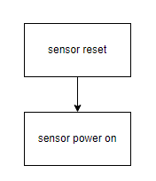
Non-MIPI sensors (such as DVP/BT656 interfaces) do not require CSI configuration during power-up, unlike MIPI sensors. Sample code is as follows:
static int pCus_poweron(ss_cus_sensor *handle, u32 idx)
{
    ISensorIfAPI *sensor_if = handle->sensor_if_api;
    SENSOR_DMSG("[%s] ", __FUNCTION__);

    //Sensor Disable
    sensor_if->PowerOff(idx, CUS_CLK_POL_NEG); // Pull the power down pin to an invalid level
    sensor_if->Reset(idx, CUS_CLK_POL_NEG); // Pull the reset pin to an invalid level
    SENSOR_USLEEP(1000);

    //Sensor power on sequence
    sensor_if->MCLK(idx, 1, handle->mclk); // Enable mclk output
    SENSOR_USLEEP(2000);
    sensor_if->Reset(idx, CUS_CLK_POL_POS); // Pull the reset pin to the trigger level
    SENSOR_USLEEP(1000);
    sensor_if->PowerOff(idx, CUS_CLK_POL_POS); // Pull the pwdn pin to the trigger level
    SENSOR_MSLEEP(5);
    return SUCCESS;
}
Typical power-off flow
-
MIPI sensor
The power-off sample code is as follows:
static int pCus_poweroff(ss_cus_sensor *handle, u32 idx) { ISensorIfAPI *sensor_if = handle->sensor_if_api; SENSOR_DMSG("[%s] power low\n", __FUNCTION__); sensor_if->PowerOff(idx, CUS_CLK_POL_NEG); sensor_if->Reset(idx, CUS_CLK_POL_NEG); SENSOR_USLEEP(1000); sensor_if->SetCSI_Clk(idx, CUS_CSI_CLK_DISABLE); sensor_if->MCLK(idx, 0, handle->mclk); return SUCCESS; } -
DVP/bt656/bt1120 sensor
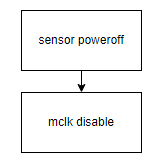
Non-MIPI sensors (such as DVP/BT656 interfaces) do not require disable CSI clk during power-off, unlike MIPI sensors. Sample code is as follows:
static int pCus_poweroff(ss_cus_sensor *handle, u32 idx)
{
    ISensorIfAPI *sensor_if = handle->sensor_if_api;
    SENSOR_DMSG("[%s] power low\n", __FUNCTION__);
    sensor_if->PowerOff(idx, CUS_CLK_POL_NEG);
    sensor_if->Reset(idx, CUS_CLK_POL_NEG);
    SENSOR_USLEEP(1000);
    sensor_if->MCLK(idx, 0, handle->mclk);
    return SUCCESS;
}
2.2.2 ResolutionConfigration
It mainly implements the functions of getting and setting Resolution, and the logic is relatively simple
/* Get the number of supported Resolutions*/
static int pCus_GetVideoResNum(ss_cus_sensor *handle, u32 *ulres_num)
{
    *ulres_num = handle->video_res_supported.num_res;
    return SUCCESS;
}
/* Get the information of a certain Resolution*/
static int pCus_GetVideoRes(ss_cus_sensor *handle, u32 res_idx, cus_camsensor_res **res)
{
    u32 num_res = handle->video_res_supported.num_res;
    if (res_idx >= num_res) {
        return FAIL;
    }
    *res = &handle->video_res_supported.res[res_idx];
    return SUCCESS;
}
/* Get the information of Resolution being used */
static int pCus_GetCurVideoRes(ss_cus_sensor *handle, u32 *cur_idx, cus_camsensor_res **res)
{
    u32 num_res = handle->video_res_supported.num_res;
    *cur_idx = handle->video_res_supported.ulcur_res;
    if (*cur_idx >= num_res) {
        return FAIL;
    }
    *res = &handle->video_res_supported.res[*cur_idx];
    return SUCCESS;
}
/* Set the Resolution index to be used */
static int pCus_SetVideoRes(ss_cus_sensor *handle, u32 res_idx)
{
    u32 num_res = handle->video_res_supported.num_res;
    if (res_idx >= num_res) {
        return FAIL;
    }
    handle->video_res_supported.ulcur_res = res_idx;
    return SUCCESS;
}
2.2.3 Sensor Init/Deinit
The goal of Sensor Init is generally to initialize the sensor and output the data according to the established target. Here we need the init table that the manufacturer wants, that is, a set of I2C configurations. The typical operation is to convert the table into I2C_ARRAY, and then write these configurations to the sensor through the relevant read and write interfaces of I2C.
Init table conversion
I2C_ARRAY has been defined in \sdk\driver\SensorDriver\drv\pub\sensor_i2c_api.h. The structure prototype and conversion examples are as follows:
typedef struct _I2C_ARRAY{
    u16 reg; /**< Register address.*/
    u16 data; /**< Data.*/
} I2C_ARRAY;
/*
    i2c init table
    0x3280,0x00,
    0x3281,0x00,
    0x3301,0x3c,
......
*/
const I2C_ARRAY Sensor_init_table_8M30fps[] ={
    {0x3280, 0x00},
    {0x3281,0x00},
    {0x3301,0x3c},
......
}
I2C read and write interface
The following macros can be used directly for I2C reading and writing:
#define SensorReg_Read(_reg,_data)      (handle->i2c_bus->i2c_rx(handle->i2c_bus, &(handle->i2c_cfg),_reg,_data))
#define SensorReg_Write(_reg,_data)     (handle->i2c_bus->i2c_tx(handle->i2c_bus, &(handle->i2c_cfg),_reg,_data))
#define SensorRegArrayW(_reg,_len)      (handle->i2c_bus->i2c_array_tx(handle->i2c_bus, &(handle->i2c_cfg),(_reg),(_len)))
#define SensorRegArrayR(_reg,_len)      (handle->i2c_bus->i2c_array_rx(handle->i2c_bus, &(handle->i2c_cfg),(_reg),(_len)))
Init function
Prepare the init table conversion and I2C read and write interface to implement Sensor Init/deinit. The sample code is as follows:
static int pCus_init_linear_8M30fps(ss_cus_sensor *handle)
{
    int i,cnt;
    for(i=0;i< ARRAY_SIZE(Sensor_init_table_8M30fps);i++)
    {
        if(Sensor_init_table_8M30fps[i].reg==0xffff)
        {
            SENSOR_MSLEEP(Sensor_init_table_8M30fps[i].data);
        }
        else
        {
            cnt = 0;
            while(SensorReg_Write(Sensor_init_table_8M30fps[i].reg, Sensor_init_table_8M30fps[i].data) != SUCCESS)
            {
                cnt++;
                SENSOR_DMSG("Sensor_init_table -> Retry %d...\n",cnt);
                if(cnt>=10)
                {
                    SENSOR_DMSG("[%s:%d]Sensor init fail!!\n", __FUNCTION__, __LINE__);
                    return FAIL;
                }
                SENSOR_MSLEEP(10);
            }
        }
    }
    return SUCCESS;
}

// Deinit can be left blank if there is no clear requirement.
static int cus_camsensor_release_handle(ss_cus_sensor *handle)
{
    return SUCCESS;
}
2.2.4 SensorDriver callback registration
When you have completed the above code, congratulations, the last step is to register these functions to the callback interface in the ss_cus_sensor structure, and the Sensor is ready to flow. The registration process is generally placed in init_handle. The example is as follows
int cus_camsensor_init_handle(ss_cus_sensor* drv_handle)
{
......
    handle->pCus_sensor_poweron              = pCus_poweron ;
    handle->pCus_sensor_poweroff         = pCus_poweroff;

    handle->pCus_sensor_release              = cus_camsensor_release_handle;
    handle->pCus_sensor_init             = pCus_init_linear_8M30fps;

    handle->pCus_sensor_GetVideoResNum       = pCus_GetVideoResNum;
    handle->pCus_sensor_GetVideoRes          = pCus_GetVideoRes;
    handle->pCus_sensor_GetCurVideoRes       = pCus_GetCurVideoRes;
    handle->pCus_sensor_SetVideoRes          = pCus_SetVideoRes;
......
}
After completion, you can directly run any demo to output the stream. However, at this time, the picture may be dark due to the low exposure and gain configuration of inittable. This is a normal phenomenon. You need to complete AE porting to achieve automatic brightness adjustment.
2.3 Sensor Basic Adjustment
2.3.1 Sensor FPS calculation principle
FPS (Frame per second), frame rate refers to the number of image frames that are completely read out per unit time, and the unit is fps. A sensor with a resolution of 1080P@30FPS can output 30 1920x1080 pixel image data per second.
In other words, the sensor needs to send a frame every 1s/30=33.333ms. There is no concept of time in the sensor. The basic unit of timing refers to the period of the pixel clock. The relevant time is generally determined by the following parameters:
-
PCLK ( Pixel clock ): The clock that controls pixel output, i.e., pixel sampling clock. One clk samples one pixel, in MHz. It indicates the number of pixels sampled per unit time (per second).
-
HTS ( Horizontal total size ): The length of a line, that is, how many pixels each line contains, in pixels.
-
VTS ( Vertical total size ): The length of a frame, that is, the number of lines in each frame, unit line
After understanding the above three parameters, according to the following formula:
A pixel sampling period is: pixel_time = 1s/PCLK
The time taken for a line is: line_period(H_time) = HTS * pixel_time
The time taken for one frame is: V_time = VTS * H_time
The output frame rate of the Sensor is: FPS = 1s/V_time
According to the above process, the following calculation formula can be obtained:
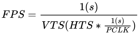
From the above formula, we can see that if we want to increase FPS, we can reduce VTS/HTS or increase the frequency of Pclk. However, these parameters cannot be adjusted infinitely. Their upper and lower limits need to be confirmed with the sensor manufacturer and can only be adjusted within a reasonable range.
Generally speaking, only VTS is controlled to reduce or increase FPS. In a few cases, HTS needs to be adjusted. PCLK is generally not adjusted.
2.3.2 FPS Adjustment
Usually we only use VTS to control the frame rate, so the formula we need becomes: FPS = 1s/V_time = 1s/ VTS * H_time
Assuming that the outgoing stream configuration of the init table we get is 30fps, we can get V_time = 1s/30fps = 33.333ms
VTS needs to first consult the DataSheet to find the register that controls the frame length. Taking a certain sensor model as an example, the register description is as follows:

Determine the register location as 0x320E[6:0]/0x320F. Do not use the default value 0x08CA as VTS for calculation. Instead, check whether the register is configured in the init table. If not, use the default value in the datasheet.
Here we assume that VTS=0x08CA=2250, then H_time = V_time / VTS = 33.333ms / 2250 = 14815 ns
The calculation formula of FPS can be updated to FPS = 1s/(VTS*14815ns), that is, VTS = 1s/(FPS*14815ns)
According to the above calculation formula, given the desired FPS, the value of VTS can be calculated to write all the parameters and formulas required for the Sensor register to be organized.
| Register address | reg_addr | {0x320e[6:0], 0x320f} |
|---|---|---|
| Framerate limit | fpx_max | 30 |
| Frame rate minimum | fps_min | 0 |
| Line_period(H_time) | 14815ns | |
| Initial frame length | init_vts | 2250 |
The VTS calculation formula is:
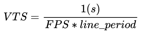
You can realize the control calculation of FPS. The sample code is as follows:
const static I2C_ARRAY vts_reg[] = {
    {0x320e, 0x08},
    {0x320f, 0xCA},
};
u32 Preview_line_period = 14815;
u32 vts = 2250;
u32 preview_fps = 30;

static int pCus_SetFPS(ss_cus_sensor *handle, u32 fps)
{
    u32 max_fps = handle->video_res_supported.res[handle->video_res_supported.ulcur_res].max_fps; //Need to be filled in init handle
    u32 min_fps = handle->video_res_supported.res[handle->video_res_supported.ulcur_res].min_fps; //Write in init handle and you can use it directly

    if(fps>=min_fps && fps <= max_fps){
        vts = 1000000000/(fps*Preview_line_period);
    }else if((fps >= (min_fps*1000)) && (fps <= (max_fps*1000))){        // 1000x parameter for judgment
        vts = 1000000000/(fps*Preview_line_period/1000);                 // Using u32 type may cause overflow during calculation in some cases, you can use u64 instead
    }else{
        SENSOR_DMSG("[%s] FPS %d out of range.\n",__FUNCTION__,fps);
        return FAIL;
    }

    vts_reg[0].data = (vts >> 8) & 0x00ff;
    vts_reg[1].data = (vts >> 0) & 0x00ff;
    SensorReg_Write(vts_reg[0].reg, vts_reg[0].data);
    SensorReg_Write(vts_reg[1].reg, vts_reg[1].data);
    return SUCCESS;
}

static int pCus_GetFPS(ss_cus_sensor *handle)
{
    32 vts = (vts_reg[0].data << 8) | (vts_reg[1].data << 0);

    if (preview_fps >= 1000)
        preview_fps = 1000000000000ULL/(vts*Preview_line_period);
    else
        preview_fps = 1000000000/(vts*Preview_line_period);
    return preview_fps;
}
After implementation, register it to the Sensor Interface module
int cus_camsensor_init_handle(ss_cus_sensor* drv_handle) {
{
......
    handle->pCus_sensor_GetFPS          = pCus_GetFPS;
    handle->pCus_sensor_SetFPS          = pCus_SetFPS;
......
}
2.3.3 Orien Adjustment
Orien adjustment refers to flipping the sensor output horizontally (mirror) or vertically (flip)
The relevant register description of a certain model sensor Datasheet is as follows:
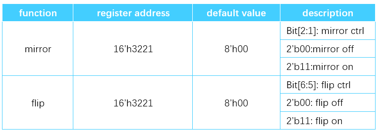
const static I2C_ARRAY mirror_reg[] =
{
    {0x3221, 0x00}, // mirror[2:1], flip[6:5]
};

static int pCus_SetOrien(ss_cus_sensor *handle, CUS_CAMSENSOR_ORIT orit)
{
    switch(orit) {
        case CUS_ORIT_M0F0:
            mirror_reg[0].data = 0x00;
        break;
        case CUS_ORIT_M1F0:
            mirror_reg[0].data = 0x06;
        break;
        case CUS_ORIT_M0F1:
            mirror_reg[0].data = 0x60;
        break;
        case CUS_ORIT_M1F1:
            mirror_reg[0].data = 0x66;
            break;
        default :
            break;
    }
    SensorReg_Write(mirror_reg[0].reg, mirror_reg[0].data);
    return SUCCESS;
}

static int pCus_GetOrien(ss_cus_sensor *handle, CUS_CAMSENSOR_ORIT *orit) {
    char sen_data;
    sen_data = mirror_reg[0].data;
    SENSOR_DMSG("[%s] mirror:%x\r\n", __FUNCTION__, sen_data & 0x66);
    switch(sen_data & 0x66)
    {
        case 0x00:
            *orit = CUS_ORIT_M0F0;
            break;
        case 0x06:
            *orit = CUS_ORIT_M1F0;
            break;
        case 0x60:
            *orit = CUS_ORIT_M0F1;
            break;
        case 0x66:
            *orit = CUS_ORIT_M1F1;
            break;
    }
    return SUCCESS;
}

//Remember to register in init handle
......
    handle->pCus_sensor_GetOrien          = pCus_GetOrien;
    handle->pCus_sensor_SetOrien          = pCus_SetOrien;
......
2.3.4 AEStatusNotify Mechanism
In the previous sample code, the value to be sent to the register is often calculated and sent directly to the sensor through the I2C interface. In most cases, this approach will not cause any major problems. However, in some sensors or in some special scenarios, the sensor may have timing requirements, such as
-
Must be placed in the blanking between the end of the frame and the start of the next frame to take effect
-
ISP hopes that all changes to the Sensor outbound flow can take effect in the same frame
Therefore, a mechanism is needed to meet the above timing requirements. Before implementing this function, modify the previous FSP and orien func and use a dirty variable instead of the direct write action.
bool reg_dirty = false;
bool orient_dirty = false;

static int pCus_SetFPS(ss_cus_sensor *handle, u32 fps)
{
......
    vts_reg[0].data = (vts >> 8) & 0x00ff;
    vts_reg[1].data = (vts >> 0) & 0x00ff;
    //SensorReg_Write(vts_reg[0].reg, vts_reg[0].data);
    //SensorReg_Write(vts_reg[1].reg, vts_reg[1].data);
    reg_dirty = true;
......
    return SUCCESS;
}
static int pCus_SetOrien(ss_cus_sensor *handle, CUS_CAMSENSOR_ORIT orit)
{
......
    //SensorReg_Write(mirror_reg[0].reg, mirror_reg[0].data);
    orient_dirty = true;
    return SUCCESS;
}
After the modification, implement the following sample code:
static int pCus_AEStatusNotify(ss_cus_sensor *handle, u32 idx, CUS_CAMSENSOR_AE_STATUS_NOTIFY status)
{
    switch(status)
    {
        case CUS_FRAME_INACTIVE:
            break;
        case CUS_FRAME_ACTIVE:
            if(orient_dirty)
            {
                SensorRegArrayW((I2C_ARRAY*)params->tMirror_reg, ARRAY_SIZE(mirror_reg));
                orient_dirty = false;
            }
            if(reg_dirty)
            {
                SensorRegArrayW((I2C_ARRAY*)vts_reg, ARRAY_SIZE(vts_reg));
                reg_dirty = false;
            }
            break;
        default :
            break;
    }
    return SUCCESS;
}
If the user wants the changes of orien and fps to take effect in the same frame, the following process can be used to call:
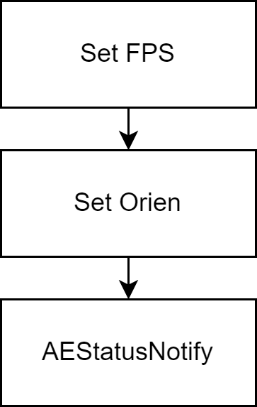
This ensures that these parameters can take effect in the same frame. The same is true when the Sensor has more parameters. This can be achieved by writing the sensor register in AEnotify.
The parameter CUS_CAMSENSOR_AE_STATUS_NOTIFY of this interface only uses one type. The difference between the two methods is as follows. You can choose according to your needs.
typedef enum {
    CUS_FRAME_INACTIVE = 0, /**Triggered by the Frame start interrupt*/
    CUS_FRAME_ACTIVE = 1,   /**Triggered by the Frame end interrupt, ensuring that the action of the next register is during the VBlanking period of the current Frame*/
} CUS_CAMSENSOR_AE_STATUS_NOTIFY;
2.4 AE Adjustment
2.4.1 Basic Principles of Automatic Exposure
AE (Auto Exposure) automatic exposure, the function implemented by the AE module is to obtain the exposure of the current image based on the automatic metering system, and then automatically configure the lens aperture, sensor shutter and gain to obtain the best image quality
A simple schematic diagram is as follows
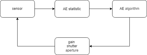
Each image sent by the sensor is statistically analyzed according to certain rules to obtain the input parameters required by the AE algorithm. The AE algorithm obtains the parameters that need to be updated to the sensor based on the current statistical values and the adjustment capabilities provided by the sensor (the adjustment range and range of each sensor are different). Finally, the interface provided by the sensor driver is used to write the parameters to the sensor.
Tips: AE automatic exposure does not only refer to the adjustment of the exposure time parameter of the Sensor, but can be simply understood as the adjustment of the brightness of the entire picture.
2.4.2 Exposure/Shutter Adjustment
Exposure adjustment is also called shutter adjustment. The shutter opening and closing determines the length of exposure time. First, you need to confirm the adjustment capability of the sensor. Check the sensor datasheet and find the exposure adjustment section. Take a certain sensor model as an example. Its exposure-related registers are as follows:
The important parameters are as follows
| Register address | reg_addr | {0x3e00[3:0], 0x3e01[0:7], 0x3e02[7:4]} |
|---|---|---|
| Exposure limit | expo_max | VTS - 4 ( |
| Exposure lower limit | expo_min | 0 |
| Exposure step | expo_step | 1 |
| Exposure delay time | expo_delay | 2 |
Fill in the following parameters in the init handle
handle->sensor_ae_info_cfg.u8AEShutterDelay = 2;
handle->sensor_ae_info_cfg.u8AEShutterCtrlNum = 1;

/*Gain setting is the same*/
handle->sensor_ae_info_cfg.u8AEGainDelay = SENSOR_GAIN_DELAY_FRAME_COUNT;
handle->sensor_ae_info_cfg.u8AEGainCtrlNum = SENSOR_GAIN_CTRL_NUM;
The calculation of exposure time is actually similar to FPS. Generally speaking, the unit is line, which is also determined by HTS. It is consistent with H_time/line_period in FPS calculation. The calculation formula of exposure time is as follows:

What needs attention here is the calculation of the upper limit of exposure. The derivation process is as follows:
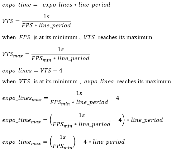
With the above parameters and formulas, you can start to implement the following sample code:
u32 Preview_MIN_FPS = 3;
u32 Preview_line_period = 14815;

//Keep the initial value consistent, according to init table
I2C_ARRAY expo_reg[] = {  // max expo line vts-4!
    {0x3e00, 0x00}, // [3:0] expo [20:17]
    {0x3e01, 0x30}, // [7:0 ]expo[16:8]
    {0x3e02, 0x10}, // [7:4] expo[3:0]
};

static int pCus_GetShutterInfo(ss_cus_sensor* handle,CUS_SHUTTER_INFO *info)
{
    info->max = 1000000000/Preview_MIN_FPS - 4*Preview_line_period;
    info->min = Preview_line_period;
    info->step = Preview_line_period;
    return SUCCESS;
}

static int pCus_SetAEUSecs(ss_cus_sensor *handle, u32 us) {
    u32 lines = 0;

    lines = (1000*us)/Preview_line_period; // Preview_line_period in ns
    if(lines<=1) lines=1;
    if (lines > vts-4) {
        lines = vts - 4;
    }

    lines = lines<<4;
    expo_reg[0].data = (lines>>16) & 0x0f;
    expo_reg[1].data = (lines>>8) & 0xff;
    expo_reg[2].data = (lines>>0) & 0xf0;
    reg_dirty = true;
    return SUCCESS;
}

static int pCus_GetAEUSecs(ss_cus_sensor *handle, u32 *us) {
    int rc=0;
    u32 lines = 0;
    lines |= (u32)(expo_reg[0].data&0x0f)<<16;
    lines |= (u32)(expo_reg[1].data&0xff)<<8;
    lines |= (u32)(expo_reg[2].data&0xf0)<<0;
    lines >>= 4;
    *us = (lines*Preview_line_period)/1000; //return us
    return rc;
}

//Callback Registration
......
    handle->pCus_sensor_GetAEUSecs      = pCus_GetAEUSecs;
    handle->pCus_sensor_SetAEUSecs      = pCus_SetAEUSecs;
    handle->pCus_sensor_GetShutterInfo  = pCus_GetShutterInfo;
......

//AEnotify effective
static int pCus_AEStatusNotify(ss_cus_sensor *handle, u32 idx, CUS_CAMSENSOR_AE_STATUS_NOTIFY status)
{
......
        if(params->reg_dirty)
        {
            SensorRegArrayW(expo_reg, ARRAY_SIZE(expo_reg));
            SensorRegArrayW(vts_reg, ARRAY_SIZE(vts_reg));
            params->reg_dirty = false;
        }
......
}
2.4.3 The interaction between exposure and FPS
If there is such a requirement, the FPS should be 30 and the exposure time should be 40ms
An FPS of 30 means that the sensor needs to read out an image every 33.3ms. The theoretical upper limit of the exposure time is 33.3ms, but it is generally impossible to reach this value. Time must be left for image processing. Therefore, the above requirement is unreasonable and impossible.
The upper limit formula of exposure derived above is as follows:
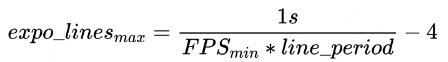
It can be seen that exposure is actually affected by FPS. The smaller the FPS, the longer the exposure time can be adjusted.
In some low-brightness scenes, the frame rate can be sacrificed to increase the brightness of the picture.
It should be noted that the behaviors of different sensors may differ. There are two types:
-
Just adjusting the number of exposure lines can reduce the frame rate. When expo_lines > VTS, VTS = expo_lines + X
-
The sensor will limit the maximum value of exposure_lines to VTS - X. It is useless to increase the number of exposure lines. You must adjust VTS and exposure_lines at the same time.
tips : If the value of X is not specified in the data sheet, please confirm with the sensor vendor. Here, X=4 for this sensor model
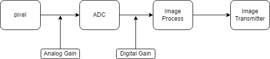
2.4.4 Gain Adjustment
Gain adjustment is consistent with the concept in the signal system. It amplifies the signal. In the sensor, it ultimately affects the overall brightness of the image. Usually, sensors support two adjustment functions.
-
Analog gain
Amplify the analog signal before ADC conversion. The analog gain amplifies the signal and introduces noise only once.
-
Digital gain
Amplify the digital signal converted by ADC. While amplifying the signal, the noise brought by digital gain will be introduced in multiple cascades. Compared with analog gain, the digital signal also contains quantization noise and readout circuit noise.
Generally speaking, the effect of analog gain is better than that of digital gain. Different manufacturers have different methods for adjusting sensor gain. There are also differences in the calculation methods of different models from the same manufacturer. Some manufacturers do not even write it in the data sheet, such as GC (galaxy core) and OV (omnivison). You need to ask the manufacturer's FAE for the calculation formula.
Grade-by-step coarse and fine adjustment
Refer to the data sheet of a certain sensor model to obtain the gain specification parameters, as follows:
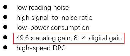
The total gain multiple calculation: total_gain = analog_gain * digital_gain = 49.6*8 = 396.8 times
Analog gain and digital gain can be used together. Generally speaking, analog gain should be adjusted first. If it still cannot meet the requirements after being pulled to the maximum, digital gain should be adjusted. Of course, you can also use only one of analog gain or digital gain and then find the adjustment method, as follows:
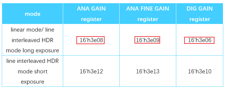
The sensor adjustment method is:
-
analog_gain uses two sets of registers to control, 0x3e08: coarse adjustment (Coarse_Again), 0x3e09: fine adjustment (Fine_Again)
-
digtal_gain has only one register, 0x3e06, but its precision is not high
In addition, the sensor also provides an analog_gain table
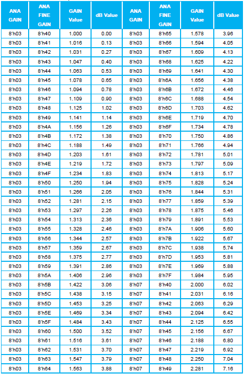
The simplest way is to make the above table into an array and get the closest approximation by looking up the table, but this table is too large, it will take a lot of effort to create it manually.
Generally speaking, most manufacturers will provide a calculation formula, which includes the mapping relationship between the target gain and the register. Through this equation, the required register value can be calculated. If the manufacturer does not provide a calculation formula, we can also find the relationship between gain and reg_value by ourselves by finding the pattern.
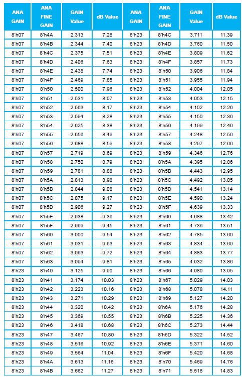
For the above table, when 1\<= gain_value \< 2, coarse_again_reg is fixed to 0x3, coarse_again is fixed to 1, fine_again_reg takes the value of 0x40~0x7F ( 64~127), reg_step=1/64. For every 1bit change in fine_again_reg, the gain changes by (gain_max-gain_min)*reg_step, which is written as reg_unit = (gain_max-gain_min)*reg_step = (2-1)*1/64=0.015625
When 2\<= gain_value \< 3.125, coarse_again_reg is fixed to 0x7, coarse_again is fixed to 2, fine_again_reg takes the value of 0x40~0x63 (64~99), reg_step=1/36. For every 1bit change in fine_again_reg, reg_unit = (3.125-2)*1/36=0.03125
When gain_value is within other value ranges, similar rules can be found. Our goal is to find the calculation formula of fine_again_reg and gain_value, so that we can calculate the value that needs to be stored in the register according to the required gain value.
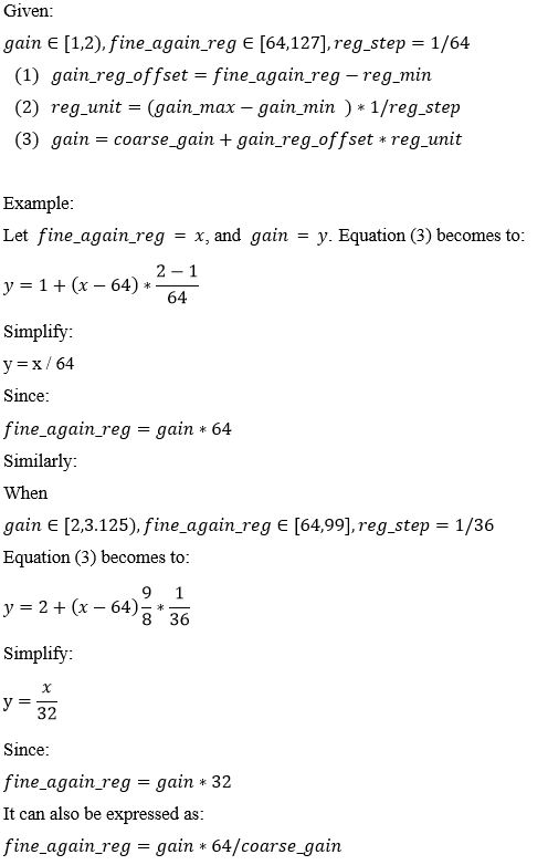
Here we get a more general calculation formula for gain and gain_value for this sensor model in the range of [1, 3.125)
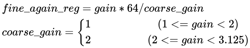
You can implement the following sample code:
I2C_ARRAY gain_reg[] = {
    {0x3e06, 0x00},
    {0x3e08, 0x03}, //coarse_Again_reg
    {0x3e09, 0x40}, //fine_Again_reg
};
#define SENSOR_MAXGAIN 3200 \\3.125*1024

static int pCus_SetAEGain(ss_cus_sensor *handle, u32 gain){
    u32 Coarse_gain,Coarse_gain_reg,Fine_gain_reg;

    if (gain <= 1024) {
        gain = 1024;
    } else if (gain > SENSOR_MAXGAIN) {
        gain = SENSOR_MAXGAIN;
    }
    if (gain < 2048) // start again  2 * 1024
    {
        Coarse_gain = 1;
        Coarse_gain_reg = 0x03;
    }
    else if (gain < 3200) // 3.125 * 1024
    {
        Coarse_gain = 2;
        Coarse_gain_reg = 0x07;
    }
    Fine_gain_reg = gain*64/(Coarse_gain*1024);
    gain_reg[2].data = Fine_gain_reg & 0xFF;
    gain_reg[1].data = Coarse_gain_reg & 0xFF;
    gain_reg[0].data = 0x00;                    //Dgain is not used
    params->reg_dirty = true;
    return SUCCESS;
}

static int pCus_GetAEGain(ss_cus_sensor *handle, u32* gain) {
    u32 Coarse_gain;
    u32 Fine_gain_reg = gain_reg[2].data;

    if(gain_reg[1].data == 0x3)
        Coarse_gain = 1;
    else if(gain_reg[1].data == 0x7)
        Coarse_gain = 2;

    *gain = (Fine_gain_reg*Coarse_gain*1024)/64;
    return SUCCESS;
}

//Callback Registration
......
    handle->pCus_sensor_GetAEGain                   = pCus_GetAEGain;
    handle->pCus_sensor_SetAEGain                   = pCus_SetAEGain;
    handle->sensor_ae_info_cfg.u32AEGain_min        = 1024;
    handle->sensor_ae_info_cfg.u32AEGain_max        = SENSOR_MAXGAIN;
......

static int pCus_AEStatusNotify(ss_cus_sensor *handle, u32 idx, CUS_CAMSENSOR_AE_STATUS_NOTIFY status)
{
......
        if(params->reg_dirty)
        {
            SensorRegArrayW(expo_reg, ARRAY_SIZE(expo_reg));
            SensorRegArrayW(gain_reg, ARRAY_SIZE(gain_reg));
            SensorRegArrayW(vts_reg, ARRAY_SIZE(vts_reg));
            params->reg_dirty = false;
        }
......
}
3. Sensor Driver Verification
3.1 Image Verification
You can use any streaming demo, run RTSP streaming, and use VLC or PotPlayer to preview the image.
3.2 FPS/Orien Control Verification
echo cmd param > /dev/sensorif
The supported commands and parameters are as follows:
| cmd | param | description | example |
|---|---|---|---|
| enable [pad] | pad: PAD ID registered by the sensor | Enable sensor | echo enable 0 >/dev/sensorif |
| disable [pad] | pad: PAD ID registered by the sensor | Disable sensor | echo disable 0 >/dev/sensorif |
| planemode [pad] [HDR mode] | pad: PAD ID registered by the sensor HDR mode: whether to use HDR |
Set the HDR mode of the sensor | echo planemode 0 1 >/dev/sensorif |
| set_res [pad] [nres] | pad: PAD ID registered by Sensor nres: resolution number |
Set the resolution output by sensor | echo set_res 0 1 >/dev/sensorif |
| fps [pad] [fpsx1000] | pad: PAD ID registered by the sensor fpsx1000: 1000 times the fps frame rate |
Set the fps output by the sensor | echo fps 0 30000 >/dev/sensorif |
| mf [pad] [mirror] [flip] | pad: PAD ID registered by the sensor mirror: whether to flip horizontally flip: whether to flip vertically |
Set the rotation of the sensor output | echo mf 0 1 1 >/dev/sensorif |
| shutter [pad] [us] | pad: PAD ID registered by the sensor us: exposure time, unit is us |
Set sensor exposure time | echo shutter 0 30000 >/dev/sensorif |
| gain [pad] [gainx1024] | pad: Sensor registered PAD ID gainx1024: 1024 times of gain |
Set sensor gain | echo gain 0 2048 >/dev/sensorif |
| notify [pad] [notify_type] | pad: PAD ID registered by Sensor notify_type: 1 for direct notification, 0 for triggering at the end of the frame |
Execute AEnotify, notify when actively triggered or at the end of the frame | echo notify 0 1 >/dev/sensorif |
After the outflow is successful, use the above command to adjust the Sensor
3.3 AE Verification
AE affects the brightness of the picture. To determine whether AE is working, the simplest way to check is as follows:
- When streaming via RTSP, cover the sensor lens. If AE is working, the image brightness will be very high. Then quickly remove the cover and observe whether the image brightness is overexposed, flickers slightly, and is stable.
For a more detailed inspection, you need to use IQtool to connect and check the gain/exposure value changes to make a judgment.
4. FAQ
Q1: How to check if VIF has received data
Check the VIF image statistics and interrupt statistics, please refer to MI VIF API Section 5.PROCFS INTRODUCTION
Q2: What to check in imaging tests
- Flip/Mirror
Verification Method:
1.1 Follow Section 3.1 to stream via RTSP and preview the image using VLC or PotPlayer. Input the UT command described in Section 3.2 to confirm the flip/mirror effect.
1.2 When flipping in VIF-ISP Frame Mode, ensure that no double vsync occurs in the mi_vif proc node. Some sensors may exhibit data anomalies during flipping—if this happens, use the SetSkipFrame interface to skip N (N=1,2,...) frames as a workaround.
- Exposure/Gain
Verification Method:
2.1 During AE Verification (Section 3.3), when streaming to the ISP, 3A algorithms will adjust exposure automatically, making UT command adjustments less noticeable. In this case, use IQ Tool to switch AE to manual mode and manually adjust exposure to observe image changes. For auto-exposure validation, enable AE logs or connect IQ Tool, then perform "cover-uncover-cover" cycles with the lens. Expected behavior:AE parameters should change significantly and stabilize adn the image should not appear overly dark or overexposed.
2.2 The most direct method is to add logs in the driver’s AeStatusNotify function to print the current register values written to the sensor. Alternatively, read back AE-related registers via I2C to confirm the driver’s write operations take effect.
2.3 For fine-grained exposure/gain anomalies (e.g., gain linearity issues), compare the function implementation with the datasheet to check for hardcoded/incorrect parameters. If unresolved, consult the sensor vendor.
Q3: Timing for applying gain/shutter/mirror/flip register settings
For most sensors, register changes take effect delayed, meaning they only apply at the next frame start. Therefore, it is generally recommended for the driver to write these registers uniformly in AeStatusNotify(CUS_FRAME_ACTIVE), ensuring all sensor modifications take effect in the same frame. However, some sensors may have immediate-effect registers (where changes apply right after writing). In such cases, the driver must write them during the vblanking period, i.e., inside AeStatusNotify(CUS_FRAME_INACTIVE).
Q4: Sensor screen tearing or display corruption when do mirror or flip
Some sensors may experience screen corruption or tearing when performing mirror/flip operations. In such cases, we can use the SetSkipFrame function to skip corrupted frames. Note that this function must be called before writing to the registers. Alternatively, if the sensor supports group hold registers, configuring them can ensure that multiple register settings take effect simultaneously. This is particularly beneficial for HDR sensors, as it guarantees synchronized activation of long and short exposure settings.
sample code for using SetSkipFrame:
static int pCus_AEStatusNotify(struct __ss_cus_sensor*handle,u32 idx, CUS_CAMSENSOR_AE_STATUS_NOTIFY status)
{
    xxx_params *params = (xxx_params *)handle->private_data;
    ISensorIfAPI *sensor_if = handle->sensor_if_api;

    switch(status)
    {
        case CUS_FRAME_INACTIVE:
            break;
        case CUS_FRAME_ACTIVE:
           if(params->orient_dirty){
                sensor_if->SetSkipFrame(idx, params->expo.fps, 1u);
                SensorRegArrayW((I2C_ARRAY*)params->tMirror_reg, ARRAY_SIZE(mirror_reg));
                params->orient_dirty = false;
            }
            break;
        default :
            break;
    }
    return SUCCESS;
}
sample code for using group hold :
static int pCus_AEStatusNotify(struct __ss_cus_sensor*handle,u32 idx, CUS_CAMSENSOR_AE_STATUS_NOTIFY status)
{
    xxx_params *params = (xxx_params *)handle->private_data;
    ISensorIfAPI *sensor_if = handle->sensor_if_api;

    switch(status)
    {
        case CUS_FRAME_INACTIVE:
            break;
        case CUS_FRAME_ACTIVE:
            if(params->dirty || params->orien_dirty) {
                if(params->dirty) {
                    SensorReg_Write(0x3001,1); // Global hold on
                    SensorRegArrayW((I2C_ARRAY*)params->tExpo_reg, ARRAY_SIZE(expo_reg));
                    SensorRegArrayW((I2C_ARRAY*)params->tGain_reg, ARRAY_SIZE(gain_reg));
                    SensorRegArrayW((I2C_ARRAY*)params->tVts_reg, ARRAY_SIZE(vts_reg));
                    SensorReg_Write(0x3001,0); // Global hold off
                    params->dirty = false;
                }
            }
            break;
        default :
            break;
    }
    return SUCCESS;
}