EXTERNAL PHY PORTING SOP
REVISION HISTORY
| Revision No. | Description |
Date |
|---|---|---|
| 1.0 | 04/24/2025 | |
| 1.1 | 07/25/2025 |
1. Overview
In the process of customer support, it is inevitable to encounter the problem of adapting to a new external phy. Therefore, this article explains the points to pay attention to when adapting to the external phy.
Before reading this article, you can check out Ethernet User Guide to learn about the relevant specifications
2. Keyword Description
-
EMAC
Ethernet Media Access Controller (EMAC)
-
Ephy
Ethernet Physical Layer (Ethernet physical interface transceiver) is referred to as Ephy
-
MII
MII (Media Independent Interface) is a standard interface for connecting MAC and PHY. MII interface provides interconnection support between MAC and PHY
-
RMII
RMII (Reduced Media Independant Interface) is a simplified media independent interface, which is one of the standard Ethernet interfaces and has fewer I/O transmission pins than MII.
-
RX
Receiver or Reception.
-
TX
Transmitter or Transmission.
-
MDIO
MDIO (Management Data Input/Output), a bidirectional interface for input and output of management data.
-
MDC
MDC (Management Data Clock) , the clock signal for management data.
3. Hardware Circuit
-
Confirm that the physical connection of the pin is normal. You can measure the signal through an oscilloscope. You can consult HW CAE for this step.
-
Confirm the pairing of padmux. You can consult GPIO owner or HW CAE to confirm the correctness of padmux.
-
The external crystal frequency of phy is generally 25M, but the specific frequency needs to be confirmed according to the phy manual. The chip does not provide CLK.
4. Before adaptation, you need to obtain the necessary PHY original support
4.1. phy driver
When you get a new phy chip, you need to find the original manufacturer to provide a matching phy chip manual .
Some phy chips also require a matching phy driver. If you don't need a matching phy driver, you can use the default universal phy driver.
If you already have a related phy driver, you also need to consult the original manufacturer whether you need to update the corresponding driver .
If you need to update, you also need to find the phy manufacturer to support this part, mainly providing: corresponding code, update method, method to enable the driver, special settings and configuration, etc.
After the kernel runs after the driver is updated, use the command: ls /sys/bus/mdio_bus/drivers to confirm whether the driver has been updated successfully.
ls /sys/bus/mdio_bus/drivers
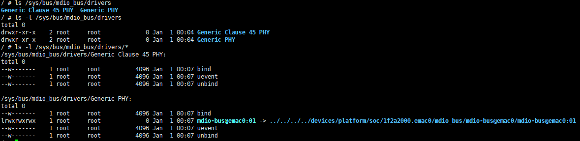
As shown in Figure 4-1, you can see that the default driver is matched: Generic PHY.
4.2. reset timing
Ask the manufacturer, or look through the phy chip manual to find the timing requirements for phy reset.
-
Reset effective time: how long it takes to pull down. Currently, pcupid is pulled down by 20ms by default.
-
Reset recovery time: how long it takes to keep pulling up. How long does it take for the phy chip to complete the internal circuit initialization after the phy chip is reset. Currently, pcupid is pulled up by 50ms by default.
Take RTL8211 as an example:
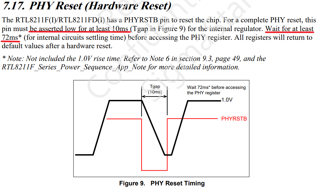
As indicated by the red line in Figure 4-2, RTL8211 requires that the reset take-effect time is at least 10ms and the reset recovery time is at least 72ms.
5. Introduction to Uboot Adaptation
5.1. padmux configuration under Uboot
- It is necessary to match padmux.dtsi with the hardware circuit.
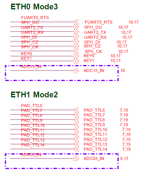
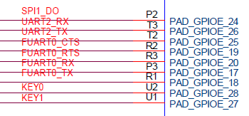
Take SSM001A-S01A-S as an example, find the pins corresponding to eth0 and eth1, and write their mapping relationship into the pcupid-ssm001a-s01a-padmux.dtsi file.
- eth0 & eth1 padmux
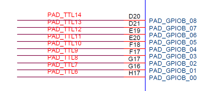
//eth0 rmii
<PAD_GPIOE_08            PINMUX_FOR_GPIO_MODE             MDRV_PUSE_ETH0_PHY_RESET>,
<PAD_GPIOE_20            PINMUX_FOR_ETH_MODE_3            MDRV_PUSE_ETH0_COL>,
<PAD_GPIOE_21            PINMUX_FOR_ETH_MODE_3            MDRV_PUSE_ETH0_RXD0>,
<PAD_GPIOE_22            PINMUX_FOR_ETH_MODE_3            MDRV_PUSE_ETH0_RXD1>,
<PAD_GPIOE_23            PINMUX_FOR_ETH_MODE_3            MDRV_PUSE_ETH0_TX_CLK>,
<PAD_GPIOE_24            PINMUX_FOR_ETH_MODE_3            MDRV_PUSE_ETH0_TXD0>,
<PAD_GPIOE_25            PINMUX_FOR_ETH_MODE_3            MDRV_PUSE_ETH0_TXD1>,
<PAD_GPIOE_26            PINMUX_FOR_ETH_MODE_3            MDRV_PUSE_ETH0_TX_CTL>,
<PAD_GPIOE_27            PINMUX_FOR_ETH_MODE_3            MDRV_PUSE_ETH0_MDIO>,
<PAD_GPIOE_28            PINMUX_FOR_ETH_MODE_3            MDRV_PUSE_ETH0_MDC>,
//eth1 rmii
<PAD_SAR_ADC0_03         PINMUX_FOR_GPIO_MODE             MDRV_PUSE_ETH1_PHY_RESET>,
<PAD_GPIOB_00            PINMUX_FOR_ETH1_MODE_2           MDRV_PUSE_ETH1_COL>,
<PAD_GPIOB_01            PINMUX_FOR_ETH1_MODE_2           MDRV_PUSE_ETH1_RXD0>,
<PAD_GPIOB_02            PINMUX_FOR_ETH1_MODE_2           MDRV_PUSE_ETH1_RXD1>,
<PAD_GPIOB_03            PINMUX_FOR_ETH1_MODE_2           MDRV_PUSE_ETH1_TX_CLK>,
<PAD_GPIOB_04            PINMUX_FOR_ETH1_MODE_2           MDRV_PUSE_ETH1_TXD0>,
<PAD_GPIOB_05            PINMUX_FOR_ETH1_MODE_2           MDRV_PUSE_ETH1_TXD1>,
<PAD_GPIOB_06            PINMUX_FOR_ETH1_MODE_2           MDRV_PUSE_ETH1_TX_CTL>,
<PAD_GPIOB_07            PINMUX_FOR_ETH1_MODE_2           MDRV_PUSE_ETH1_MDIO>,
<PAD_GPIOB_08            PINMUX_FOR_ETH1_MODE_2           MDRV_PUSE_ETH1_MDC>,
5.2. Phy reset time configuration under Uboot
According to the reset timing information obtained in 4.2 , configure phy during initialization.
Under Uboot, you can use KConfig to configure the reset effective time (pull low) and reset recovery time (pull high).
-
EMAC0 RMII + phy reset
[*] SigmaStar drivers ---> SigmaStar EMAC ---> [*] SigmaStar EMAC [*] EMAC supply to RMII [ ] EMAC supply to IC+ Phy [ ] EMAC fix link to mii/rmii [*] EMAC phy reset reverse [*] EMAC 0 [*] EMAC0 PHY RESET (17) EMAC 0 FOR PHY RESET PAD (20) EMAC 0 FOR PHY RESET HOLD MS (50) EMAC 0 FOR PHY WAIT READY MS [ ] EMAC 1 -
The off-chip phy needs to enable the macro SSTAR_ETHERNET_RMII and switch to rmii mode.
-
Set the EMAC0 reset effective time and reset recovery time. Under the default configuration, the reset effective time is 20ms and the reset recovery time is 50ms.
-
When the padmux.dtsi file does not configure the reset pin, the pin configured by Kconfig will be used for reset. The above configuration is pad 17.
-
Depending on the board design, sometimes a reverse circuit is added. At this time, it is necessary to configure EMAC phy reset reverse. After enabling, the reset process will become software first pull up 20ms, then pull down 50ms .
For more detailed KCONFIG configuration content, please refer to 2.1. Uboot CONFIG Configuration Instructions in the Ethernet User Guide document.
5.3. Check whether mdio communication is normal
If the phy connection is normal, mdio can read the phy information normally. When the Uboot command estart is used for initialization, the phy register information will be printed, and the information is not all 0 or all F.
Or use the phy_r and phy_w commands to read the phy register information normally, and the information is not all 0 or all F.
-
Uboot is initialized normally using the estart command
# estart
phy [0]=ffff
phy [1]=786d
MAC Address 00:00:83:05:00:01
Auto-Negotiation...
Link Status Speed:100 Full-duplex:1
(Re)start EMAC...
-
Use phy_r to read phy reg under Uboot
# phy_r 0
phy read address[0] value is 3100
# phy_r 1
phy read address[1] value is 786d
-
Use phy_w to write phy reg under Uboot
# phy_w 0 0x1000
phy write address[0] value is 1000
5.4. Check whether network communication is normal
This step is to verify the correctness of the data pin. You can use ping (normal ping) or tftp (normal file transfer or upgrade) to verify.
For related content, please refer to 5.2. Uboot cmd parameter description in the Ethernet User Guide document.
6. Kernel Adaptation Introduction
6.1. Phy reset time configuration under Kernel
The reset effective time and reset recovery time under ernel are also configured through Kconfig.
EMAC0_PHY_RESET_HOLD_MS and EMAC1_PHY_RESET_HOLD_MS are the reset validity time, and the default value is 20ms.
EMAC0_PHY_RESET_WAIT_READY_MS and EMAC1_PHY_RESET_WAIT_READY_MS are the reset recovery time, the default value is 50ms.
- Configure the kernel reset effective time and reset recovery time
Device Drivers --->
    SStar Soc platform drivers --->
        (20)  Set emac0 phy reset padmux low in millisecond
        (50)  Set emac0 phy reset padmux high wait ready in millisecond
        (20)  Set emac1 phy reset padmux low in millisecond
        (50)  Set emac1 phy reset padmux high wait ready in millisecond
6.2. DTS configuration under Kernel
Refer to 6.2. Kernel DTS Configuration in the Ethernet User Guide document to configure the dts file.
Note that if an external reverse circuit is connected, the reset_reverse property needs to be configured.
6.3. padmux configuration under Kernel
Refer to 5.1. Padmux Configuration in Uboot or 6.3. Kernel Padmux Configuration in the Ethernet User Guide document to configure the padmux file.
6.4. Check whether mdio communication is normal
The kernel will connect to the phy chip through the emac_phy_connect function. You can check the boot log to see if it is connected to the phy normally.
Taking SSM001A-S01A-S as an example, the startup will perform phy connect, obtain the phy uid and match the phy driver. Generally, if the phy uid is not all 0 or all F, the phy reg information can be read normally.
- dmesg to view the phy connect status
/ # dmesg | grep emac_phy_connect
[emac_phy_connect][2999] connected mac emac0 to PHY at mdio-bus@emac0:01 [uid=02430c54, driver=Generic PHY]
Alternatively, you can read phy reg through phytool or debug node. As long as the read phy reg is not all 0 or all F, it is normal.
For the use of phytool, refer to 6.5.4. phytool in the Ethernet User Guide document.
For debug node commands, refer to 6.6.2. phyStatusWR phy read and write debug node in the Ethernet User Guide document.
6.5. Check whether network communication is normal
You can use the iperf tool under the kernel to test the stability of network communication. You can refer to 6.5.1. iperf3 in the Ethernet User Guide document.
7. Common phy adaptation issues
7.1. mdio read exception, phy id read information is all F or all 0
During the adaptation process, there is often a problem that the phy reg cannot be read, and the signals output by mdc and mdio are all FFFF or all 0.
It is recommended that HW CAE intervene to assist in checking the measurement waveform and circuit connection.
Common errors have the following reasons:
| Cause of error | Troubleshooting method | Solution |
|---|---|---|
| Physical connection abnormality | HW CAE assists in measuring waveforms, or checking circuit connections | Refer to HW CAE opinions |
| GPIO configuration abnormality | HW CAE checks padmux mapping | Modify padmux |
| GPIO cannot be pulled down or raised | Troubleshoot according to gpio problems, you can ask GPIO owner for assistance | Solve according to GPIO problems |
| Phy reset abnormality | Use an oscilloscope to measure whether the waveform of the reset pin at startup meets expectations | Refer to the phy manual for settings. In the debug stage, you can set the reset effective time and recovery time to 1s or more to ensure that the reset is normal |
7.2. The packet sending and receiving rate is not as expected, or there are problems such as packet loss.
If the rate is not as expected, it is usually a signal quality or phase problem, which needs to be investigated by HW CAE. Here are some common troubleshooting items:
-
Confirm whether the CLK provided by phy/switch is 50MHz. The MAC does not provide RX_CLK.
-
Confirm the signal amplitude or phase. If the waveform is abnormal, you need to refer to the phy manual and adjust the driving capability of the phy by adjusting the phy register.
-
Check the external crystal oscillator of the phy, which is generally 25M, but it depends on the phy manual. If the phy does not respond, the customer needs to check whether the external crystal oscillator frequency is normally supplied.
7.3. Phy driver registration exception
-
Use the command: ls /sys/bus/mdio_bus/drivers in the kernel to confirm whether the driver has been updated successfully. This command will display the drivers supported by the current device.
-
Check whether the mdio connection is normal, refer to 7.1. mdio read abnormality, phy id read information is all F or all 0 for troubleshooting.
-
If the mdio connection is normal, refer to 6.4. Check whether the mdio communication is normal to check whether the obtained phy uid is normal.
-
If the phy uid is not all 0 or all F, check whether the driver matches the phy uid. If the uid value is inconsistent with .phy_id, the driver cannot be matched.
-
icpplus driver
static struct phy_driver icplus_driver[] = {
{
    .phy_id         = 0x02430c54,
    .name           = "ICPlus IP101A/G",
    .phy_id_mask    = 0x0ffffff0,
    /* PHY_BASIC_FEATURES */
    .probe          = ip101a_g_probe,
    .config_intr    = ip101a_g_config_intr,
    .did_interrupt  = ip101a_g_did_interrupt,
    .ack_interrupt  = ip101a_g_ack_interrupt,
    .config_init    = &ip101a_g_config_init,
    .suspend        = genphy_suspend,
    .resume         = genphy_resume,
} };