Ethernet User Guide
1. Overview
In the seven-layer model (OSI model) of computer networks and the four-layer model (TCP/IP model), no specific implementation technologies for the physical layer and data link layer are explicitly specified. In the industry, Ethernet technology is commonly used for wired networks, and wireless local area network (Wi-Fi) technology is commonly used for wireless networks.
In addition to the mainstream technologies mentioned above, other technologies applicable to the physical layer and data link layer include:
- Wired networks: Serial ports (RS-232), optical fibers (SDH), USB, etc.
- Wireless networks: Bluetooth, ZigBee, cellular networks (4G/5G), etc.
All these technologies can support the operation of the TCP/IP protocol.
Both Ethernet and Wi-Fi technologies cover the physical layer and data link layer, with their core hardware and functions as follows:
Physical Layer: The core hardware is the PHY chip (also called PHY controller), which is mainly responsible for signal conversion, physical medium adaptation, and link negotiation.
MAC Sublayer of the Data Link Layer: The core hardware is the MAC chip (also called MAC controller), which is primarily responsible for frame encapsulation/decapsulation, medium access control, flow control, and error handling.
Note: Some chips integrate the MAC chip and PHY chip into a single chip (e.g., most Wi-Fi chips); very few chips lack a hardware MAC controller, requiring software emulation to implement its functions.
This chapter covers Ethernet technology, a wired network technology that defines standards for the physical layer and data link layer. SigmaStar's PCUPID series chips integrate an Ethernet data link layer controller (referred to as the EMAC controller) within the SoC, but do not integrate a physical layer PHY controller; therefore, an external Ethernet PHY chip is required.
Communication between the external PHY chip and the MAC controller of the SoC must comply with relevant standard interfaces, including:
-
100Mbps interfaces: MII/RMII
-
1000Mbps interfaces: GMII/RGMII
-
10Gbps interfaces: XGMII
2. Keyword Description
-
EMAC : Ethernet Media Access Controller. It is primarily responsible for data link layer control and management, and also for directly controlling and managing the PHY chip via MII/RMII/GMII interfaces.
-
EPHY : Ethernet Physical Layer, also known as Ethernet PHY chips, or Ethernet transceivers
-
MII : Media Independent Interface. The MII interface is a standard interface for connecting MAC and PHY, providing interconnection support between MAC and PHY. It supports network speeds of 10 Mbit/s and 100 Mbit/s.
-
RMII : Reduced Media Independant Interface. It is one of the standard Ethernet interfaces, with fewer I/O transmission pins than MII. It supports network speeds of 10 Mbit/s and 100 Mbit/s.
-
RX : Receiver, Reception
-
TX : Transmitter,Transmission
-
network card : A network card is a unified concept, typically referring to hardware that integrates MAC (Media Access Control) and PHY (Physical Layer) functions, embodying the implementations of both the data link layer and the physical layer. However, the hardware form of a "network card" varies in different scenarios:
- Independent network cards for desktop PCs: Such as Ethernet cards from brands like Realtek and Intel, they are usually complete "MAC + PHY" hardware modules. They contain both independent MAC chips and PHY chips, as well as the communication interface between them, hence being called "independent network cards".
- Network cards in embedded SoCs: Many embedded SoCs integrate a MAC controller internally, meaning the "MAC function" is implemented by an internal module of the SoC. The PHY chip is usually an external independent chip, connected to the MAC built into the SoC via interfaces like MII/RMII. In this case, the hardware form of the "network card" is a combination of "SoC-integrated MAC + external PHY chip + interface circuits (e.g., RMII)". Additionally, some embedded SoCs adopt a more highly integrated design, integrating the PHY function into the SoC to form an integrated solution of "SoC-integrated MAC + integrated PHY". In this scenario, the hardware form of the network card can be simplified to "SoC-integrated MAC + integrated PHY, along with the communication bus between them", eliminating the need for an additional external PHY chip. This effectively reduces the complexity of hardware design and costs.
3. Function Description
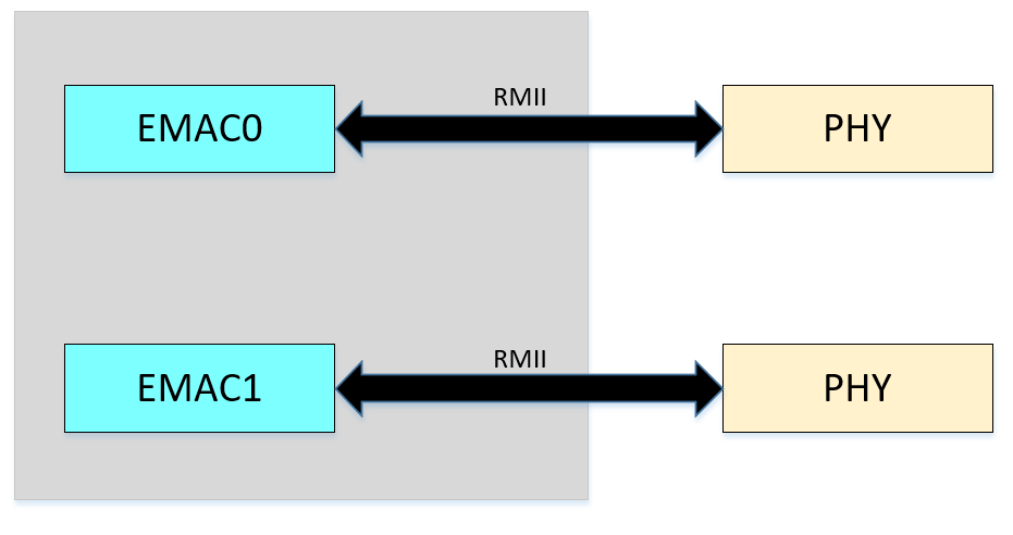
The Ethernet framework of the PCUPID series chips is shown in the diagram. The SoC integrates two EMAC controllers: EMAC0 and EMAC1. These two EMAC controllers only support the RMII interface.
**From a hardware perspective: **
-
EMAC0 : Only supports RMII with external Ephy (100M PHY chip)
-
EMAC1 : Only supports RMII with external Ephy (100M PHY chip)
**From a software perspective: **
-
uboot
 EMAC0 : RMII
 EMAC1 : RMII (Disabled by default)
 Note: Only one EMAC can be enabled simultaneously under U-Boot
-
kernel
 EMAC0 : RMII
 EMAC1 : RMII (Disabled by default)
 Note: Both EMACs can be enabled simultaneously under the kernel
The EMAC controller supports the following functions
-
network traffic control
-
network storm protection
-
network interrupt aggregation
3.1 network traffic control
The EMAC controller of the PCUPID series chips supports flow control in full-duplex mode, which is implemented through "PAUSE frames". It mainly addresses the issue caused by inconsistent processing speeds between the two ends of data transmission. When the receiving end cannot process data in a timely manner, it will send a PAUSE_ON frame. Upon receiving the PAUSE_ON frame, the transmitting end immediately stops sending data. The transmitting end resumes data transmission only when it receives a PAUSE_OFF frame, or when the PAUSE time expires and no new PAUSE_ON frame is received. Flow control can effectively regulate the data transmission process and prevent data loss.
Example illustration: When a 100M network card sends data frames to a 10M network card via a switch, frame loss may occur due to buffer overflow because the 10M network card has a lower data rate. Before its buffer is about to overflow, the 10M network card proactively sends a PAUSE frame, requesting the transmitting device to pause for a period of time before resuming data transmission, thereby preventing frame loss.
Note: PAUSE frames are dedicated data packets for flow control implemented at the data link layer. They are processed automatically by the link and require no upper-layer intervention.
3.1.1 PAUSE frame format
The format of the PAUSE frame is shown in the following figure:
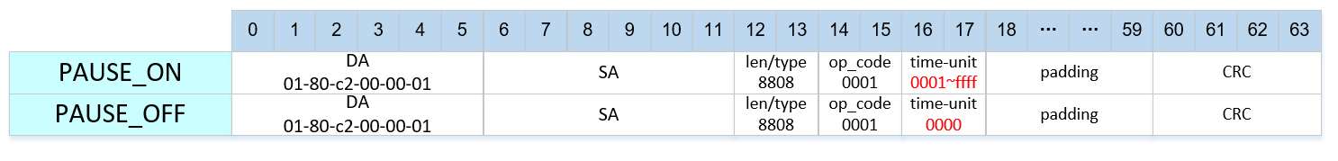
The primary focus is on the time-unit field, which is a parameter for the transmission pause duration. Its unit is the time required to transmit 512 bits at the current data rate, i.e., slot time.
-
For a PAUSE_ON packet, the time_unit is non-zero; The default value for software flow control is 0x2000, and the default value for hardware flow control is 0xffff
-
For a PAUSE_OFF packet, the time_unit is zero. Upon receiving a PAUSE_OFF packet, it indicates that flow control has been disabled, allowing normal transmission of packets (i.e., it features a wake-up function).
Common values for the time-unit are shown in the table below
| value | 10M pause time | 100M pause time |
|---|---|---|
| 20 | 1ms | 100us |
| 200 | 10ms | 1ms |
| 2000 | 100ms | 10ms |
| 20000 | 1s | 100ms |
| 60000 | 3s | 300ms |
| 65535 | 3.27s | 327ms |
3.1.2 How to enable PAUSE shutdown
The following are considerations for enabling or disabling PAUSE:
-
The macro HW_FLOW_CONTROL in hal_emac.h determines whether PAUSE frames are sent by the EMAC hardware or driver software:
- When HW_FLOW_CONTROL is enabled, PAUSE frames are sent by the EMAC hardware by default, with the time-unit value defaulting to 0xffff. The software does not participate in flow control processing.
- When HW_FLOW_CONTROL is disabled, PAUSE frames are sent by the driver software by default, with the time-unit value defaulting to 0x2000. The EMAC hardware does not participate in flow control processing.
- HW_FLOW_CONTROL is disabled by default.
-
When HW_FLOW_CONTROL is disabled, the ON/OFF state of PAUSE for the driver software can be controlled via ethtool
-
tx refers to flow control in the transmission direction, indicating whether eth0 can pause transmission when receiving PAUSE frames during traffic transmission.
-
rx refers to flow control in the reception direction, indicating whether eth0 can send PAUSE frames to the peer during traffic reception.
 Command "ethtool -a eth0" # Displays the current flow control status

 Command "ethtool -A eth0 rx on tx on" # Enables rx and tx flow control

 Command "ethtool -A eth0 rx off tx off" # Disables rx and tx flow control
-
3.1.3 How to Modify PAUSE
-
If the local device acts as the PAUSE frame receiver, the value of the time-unit field in the PAUSE frame cannot be modified.
-
If the local device acts as the PAUSE frame sender, the value of the time-unit field in the PAUSE frame can be modified by altering the driver code (static modification, not recommended). The SDK does not provide an external interface for modification, and dynamic modification during device operation is not supported temporarily.
In summary, it is not recommended to modify the value of the time-unit field in the PAUSE frame.
3.2 network storm protection
The EMAC controller of the PCUPID series chips supports network storm protection, which can limit the transmit and receive bandwidth for unicast, multicast, and broadcast. Generally, broadcast storms are more common. Broadcast data occupies a large amount of network bandwidth, causing normal services to fail or even be completely paralyzed. For broadcast storm scenarios, limiting broadcast traffic can solve the problem.
3.2.1 Principles of Storm Protection
The core principle of storm protection is to control the rate of received frames rather than focusing on the received bit rate. The PCUPID series chips implement control over the received frame rate through the token bucket mechanism in the EMAC controller hardware. The specific parameters and their functions are as follows:
-
max : The factors affecting the token bucket size (bucket depth/bucket capacity/bucket size) are as follows: The bucket size is calculated as bucket size = max / consume.The bucket size affects the ability to handle burst traffic. The default value of max is 400000, and it is not recommended to modify this value.
-
consume : Determines the generation rate of tokens. The token generation rate is the maximum limit rate for network storm protection.
The formula for calculating the token generation rate is: Token generation rate = RX_CLK / consume
The receive clock frequency (RX_CLK) of the EMAC controller is related to the network rate:
-
When operating in a 100Mbit/s network, RX_CLK = 25MHz.
-
When operating in a 10Mbit/s network, RX_CLK = 2.5MHz.
Here, "consume" represents the number of receive clock cycles required to generate 1 token.
For example, when the default "consume" value is 2500, it means that 1 token is generated every 2500 receive clock cycles. The storm limit rate in a 100Mbit/s network is:
25MHz / 2500 = 10,000 frames per second.
If the default value cannot meet the requirements, the maximum limit rate of storm protection can be adjusted by modifying the "consume" value. There are two main methods for modifying "consume": static modification and dynamic modification.
3.2.2 Static Setting of Maximum Frame Reception Rate
Static setting of the maximum frame reception rate refers to setting the maximum frame reception rate during the compilation phase by passing parameters through the API interface. Currently, the API interface provides five default levels, which are configured via three corresponding functions in Dev_EMAC_init within drv_emac.c.
| level | consume | Limit rate for 100M RMII (frames/sec) |
|---|---|---|
| 1 | 40000 | 625 |
| 2 | 20000 | 1250 |
| 3 | 10000 | 2500 |
| 4 | 5000 | 5000 |
| 5 | 2500 | 10000 |
Hal_EMAC_Netsp_Unicast_Setting(hemac->hal, TX_MAX_DEFAULT, TX_CONSUME_LEVEL_5, 1);  //Limits transmit and receive bandwidth for unicast
Hal_EMAC_Netsp_Multicast_Setting(hemac->hal, TX_MAX_DEFAULT, TX_CONSUME_LEVEL_5, 1);//Limits transmit and receive bandwidth for multicast
Hal_EMAC_Netsp_Broadcast_Setting(hemac->hal, TX_MAX_DEFAULT, TX_CONSUME_LEVEL_5, 1);//Limits transmit and receive bandwidth for broadcast
3.2.3 Dynamic Setting of Maximum Frame Reception Rate
Dynamic setting of the maximum frame reception rate refers to configuring the maximum frame reception rate by writing register values during device operation after power-on, and this rate can be dynamically modified while the device is running.
A set of default register settings is provided below, and customers can adjust them freely as needed. The control register address for emac0 is 1511, and for emac1, it is 1515. Taking storm protection for emac0 as an example: the max value (bucket size) remains at the default 40000, with the high 16 bits being 0x0006 and the low 16 bits being 0x1A80. The consume value remains at the default 2500 (hexadecimal 0x09C4).
-
Unicast frame protection
/customer/riu_w 1511 50 1A80   //Bucket size (max) - low 16 bits
/customer/riu_w 1511 51 0006   //Bucket size (max) - high 16 bits
/customer/riu_w 1511 52 09C4   //Consume - low 16 bits
/customer/riu_w 1511 68 0001   //Bit0: 1 = enable, 0 = disable
-
Multicast frame protection
/customer/riu_w 1511 58 1A80
/customer/riu_w 1511 59 0006
/customer/riu_w 1511 5A 09C4
/customer/riu_w 1511 68 0002   //Bit1: 1 = enable, 0 = disable
-
Broadcast frame protection
/customer/riu_w 1511 60 1A80
/customer/riu_w 1511 61 0006
/customer/riu_w 1511 62 09C4
/customer/riu_w 1511 68 0004   //Bit2: 1 = enable, 0 = disable
3.3 Network receive interrupt aggregation
When the EMAC RX hardware receives a frame, it triggers an interrupt to wake up the RX thread for packet reception. During high network traffic, a large number of interrupts are generated, which consumes significant CPU performance and increases CPU load.
The EMAC hardware provides a receive interrupt aggregation function (sometimes referred to as RX DELAY). Its mechanism allows the EMAC to delay triggering an interrupt immediately after receiving a frame; instead, the interrupt is triggered only when either of the following conditions is met:
-
The number of received frames reaches the set threshold (delay_num)
-
The set number of frames is not reached, but the specified time (cyc_num) has elapsed
This mechanism reduces the number of receive interrupts, thereby saving CPU resources.
In addition, the RX Delay feature includes an internal dynamic adjustment function:
-
During network idle periods, delay_num and cyc_num are automatically set to smaller values
-
During network busy periods, delay_num and cyc_num are automatically set to larger values
This dynamic adjustment function can be controlled on/off by adjusting the rx-delay-int attribute in DTS
-
Set rx-delay-int to 1, the receive interrupt aggregation function is turned on (enabled by default)
-
Set rx-delay-int to 0, the receive interrupt aggregation function is turned off
3.4 IPV6
The kernel provides the ipv6 function. If you need to use the ipv6 function, you need to enable the corresponding CONFIG, (enabled by default) .
- Enable ipv6 support in kernel
-> Networking support (NET [=y])
    -> Networking options
        -> TCP/IP networking (INET [=y])
            <*>   The IPv6 protocol
4. Hardware connection introduction
4.1 Confirmation of SoC Hardware Interfaces
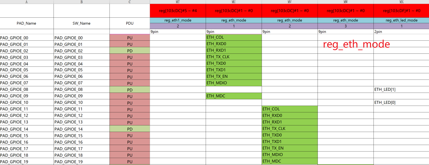
Taking the Comake_Pi_D1 board as an example, by referring to its SoC data sheet, it is confirmed that the EMAC only supports the RMII interface. The pin distribution of the RMII interface can be confirmed by checking the hardware checklist (hw checklist) of the SoC.
The following figures are sub-tables named "ARMTmux" from the hw_checklist of the on-board SoC chip of the Comake_Pi_D1 board. When different values are written to the reg_eth_mode register, the RMII pins connected to emac0 will vary accordingly; the RMII pin distribution of emac1 follows the same logic. In the device tree (dts), the file xxx_padmux.dtsi is used to specify different values for the reg_eth_mode register.
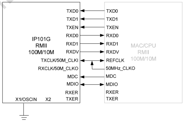
4.2 Confirmation of PHY Chip Hardware Interface
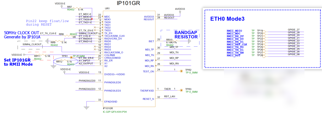
The external PHY chip model on the Comake_Pi_D1 board is IP101GR. Refer to its data sheet for the RMII interface wiring as shown in the following diagram.
4.3 Schematic Connection
The Comake_Pi_D1 board is equipped with two single network ports.
The RMII wiring between the SoC chip's emac0 and the external PHY chip is shown in the following diagram. emac0 uses reg_eth_mode=3, with pins ranging from GPIOE20 to GPIOE27.
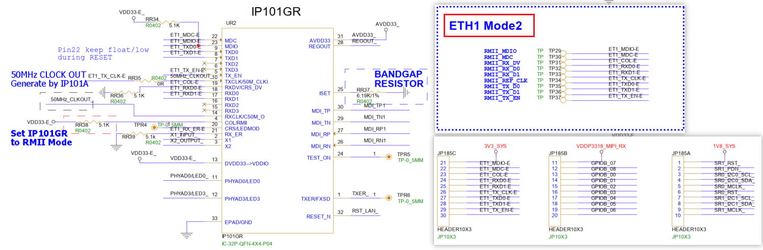
The RMII wiring between emac1 and the external PHY chip is shown in the following diagram. emac1 uses reg_eth_mode=2, with pins ranging from GPIOB0 to GPIOB8. It should be noted that for the three-row through-hole header JP185, rows B and C are not connected by default; rows A and B are connected by default for use with the sensor interface. That is, this RMII wiring is not connected, and the default emac1 network port cannot be used. If you want to use the network port corresponding to emac1, you need to connect the pins of rows B and C with a jumper cap and modify the dts configuration.
Note: The meanings of the three IDs-emac-id, eth-id on the hardware schematic, and eth-id displayed by ifconfig-are different.
-
emac-id specifies the sequence number of the EMAC controller in the SoC chip.
-
eth-id on the hardware schematic is a custom name used during schematic design; it is merely a designation with no special meaning.
-
eth-id displayed by ifconfig specifies the registration order of Ethernet devices:
-
If the registration order is emac0 followed by emac1, then eth0 displayed by ifconfig corresponds to emac0, and eth1 corresponds to emac1.
-
If the registration order is emac1 followed by emac0, then eth0 displayed by ifconfig corresponds to emac1, and eth1 corresponds to emac0.
-
If only emac1 is registered, then eth0 displayed by ifconfig corresponds to emac1, and there will be no eth1.
-
Instructions for Using the Network Ports on the Comake_Pi_D1 Development Board
-
Network Port Corresponding to emac0: The hardware is available by default, and the Device Tree (dts) has been configured with default settings. If you need to use it, you only need to confirm whether the following kernel configuration items (kernel config) are enabled, as described in the subsequent chapters.
-
Network Port Corresponding to emac1: To use it, two operations need to be completed:
-
Hardware jumper setting
-
Modification of Device Tree (dts) configuration
-
5. Uboot usage introduction
5.1. uboot config configuration
In U-Boot, both EMACs cannot be used simultaneously. emac0 is enabled by default, while emac1 is disabled by default.
-
The EMAC0 driver is enabled by default
[*] SigmaStar drivers ---> SigmaStar EMAC ---> [*] SigmaStar EMAC [*] EMAC supply to RMII [ ] EMAC supply to IC+ Phy [ ] EMAC fix link to mii/rmii [*] EMAC phy reset reverse [*] EMAC 0 [ ] EMAC0 PHY RESET [ ] EMAC 1 If EMAC0 needs to enable EMAC0 PHY RESET, the parameters are as follows: [*] SigmaStar drivers ---> SigmaStar EMAC ---> [*] SigmaStar EMAC [*] EMAC supply to RMII [ ] EMAC supply to IC+ Phy [ ] EMAC fix link to mii/rmii [*] EMAC phy reset reverse [*] EMAC 0 [*] EMAC0 PHY RESET (17) EMAC 0 FOR PHY RESET PAD (20) EMAC 0 FOR PHY RESET HOLD MS (50) EMAC 0 FOR PHY WAIT READY MS [ ] EMAC 1 -
To enable the EMAC1 driver, the EMAC0 driver needs to be disabled
[*] SigmaStar drivers  --->
    SigmaStar EMAC --->
        [*] SigmaStar EMAC
        [*]   EMAC supply to RMII
        [ ]     EMAC supply to IC+ Phy
        [ ]   EMAC fix link to mii/rmii
        [*]   EMAC phy reset reverse
        [ ]   EMAC 0
        [*]   EMAC 1
        [ ]     EMAC1 PHY RESET

If EMAC1 needs to enable EMAC1 PHY RESET, the parameters are as follows:

[*] SigmaStar drivers  --->
    SigmaStar EMAC --->
        [*] SigmaStar EMAC
        [*]   EMAC supply to RMII
        [ ]     EMAC supply to IC+ Phy
        [ ]   EMAC fix link to mii/rmii
        [*]   EMAC phy reset reverse
        [ ]   EMAC 0
        [*]   EMAC 1
        [*]     EMAC1 PHY RESET
        (121)     EMAC 1 FOR PHY RESET PAD
        (20)      EMAC 1 FOR PHY RESET HOLD MS
        (50)      EMAC 1 FOR PHY WAIT READY MS
CONFIG Description Default Value [*] SigmaStar EMAC Enable EMAC Enable [*] EMAC supply to RMII Enable RMII mode Enable [ ] EMAC supply to IC+ Phy Support ICPULS PHY Disable [ ] EMAC fix link to mii/rmii Enable fix link Disable [*] EMAC phy reset reverse Reverse pull up and down during phy reset Enable [*] EMAC 0 Enable EMAC0 Enable [*] EMAC0 PHY RESET Enable EMAC0 software phy reset Disable (17) EMAC 0 FOR PHY RESET PAD EMAC0 phy reset padmux value 17 (20) EMAC 0 FOR PHY RESET HOLD MS EMAC0 sets the hold time of low level 20ms (50) EMAC 0 FOR PHY WAIT READY MS EMAC0 sets the wait time of high level 50ms [*] EMAC 1 Enable EMAC1, uboot uses EMAC1 network card instead Disable [*] EMAC1 PHY RESET Enable EMAC1 software phy reset Disable (121) EMAC 1 FOR PHY RESET PAD EMAC1 phy reset padmux value 121 (20) EMAC 1 FOR PHY RESET HOLD MS EMAC1 sets the hold time of low level 20ms (50) EMAC 1 FOR PHY WAIT READY MS EMAC1 sets the wait time of high level 50ms -
Network commands
Command line interface --->
    Network commands --->
        [*]   bootp
        [*]     dhcp
        [*]   tftpboot
        [*]   ping
5.2 Environment Variables
In U-Boot, network-related operations primarily use commands such as ping, dhcp, and tftp. Before using these commands, you need to configure the environment variables for network usage.
5.2.1 Automatic Initialization of Network Card on Boot
The automatic initialization function of the network card on boot is configured through the autoestart environment variable.
-
If autoestart=0:
The network card will not be automatically initialized during boot. To use the network in U-Boot, you need to manually execute the estart command to initialize the network card; otherwise, the message "No ethernet found" will be displayed.
Example command:
estart //Manually initialize the network card
-
If autoestart=1:
The network card will be automatically initialized during boot.
Configuration command:
setenv -f autoestart 1 //Set network card to initialize automatically on boot
Note: Since the network card initialization process waits for the completion of network card auto-negotiation, it may slow down the boot speed. Therefore, whether to enable this configuration should be determined based on actual needs.
5.2.2 ENV configuration static IP
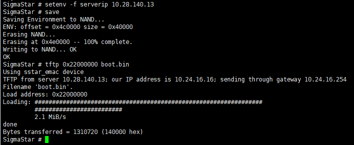
setenv -f ethact sstar_emac //Configure the network card driver to be emac
setenv -f ethaddr xx:xx:xx:xx:xx:xx:xx //Configure mac address
setenv -f ipaddr xxx.xxx.xxx.xxx //Configure static IP address
setenv -f netmask xxx.xxx.xxx.xxx //Configure IP address mask
setenv -f serverip xxx.xxx.xxx.xxx //Configure tftp server ip
save //Save configuration
5.3 Common Commands
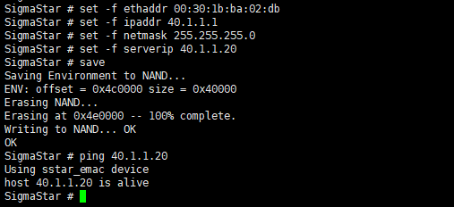
5.3.1 Setting a Static IP Address + Ping Example
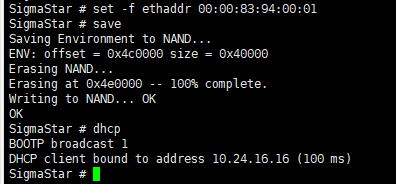
5.3.2 Example of Dynamically Obtaining an IP Address (DHCP)
setenv -f ethact sstar_emac          //Configure the network card driver as emac
setenv -f ethaddr xx:xx:xx:xx:xx:xx  //Configure the MAC address
setenv -f serverip xxx.xxx.xxx.xxx   //Configure the TFTP server IP
save                                 //Save the configuration
dhcp                                 //Obtain IP dynamically via DHCP
5.3.3 tftp Example
tftp 0x20000000 kernel //Transfer the file named "kernel" from the server to memory at starting address 0x20000000 via TFTP
6. Kernel usage introduction
6.1. Kernel CONFIG configuration
-
Enable EMAC driver
Device Drivers ---> SStar Soc platform drivers ---> [*]SSTAR_EMAC -
Enable nfs cifs
File systems --->
    Network File Systems --->
        <M> NFS client support
        <M>     NFS client support for NFS version 2
        <M>     NFS client support for NFS version 3
        <M> SMB3 and CIFS support
6.2. Kernel DTS Configuration
6.2.1 Using the Network Port of emac0
DTS Node Configuration
By default, it is enabled with status = "okay"
    emac0: emac0 {
        compatible = "sstar-emac";
        interrupts = <GIC_SPI INT_IRQ_EMAC IRQ_TYPE_LEVEL_HIGH>;
        clocks = <&CLK_emac_ahb>;
        reg = <0x0 0x1F2A2000 0x0 0x800>, <0x0 0x1F304200 0x0 0x600>, <0x0 0x00000000 0x0 0x000>;
        pad-rmii = <0x1F2079B8 0x0003 0x0003>; // pad-rmii selection from 0x0003
        bus-mode = <2>; //1:MII 2:RMII
        phy-handle = <&phy0>;
        max-speed = <100>;
        status = "okay";
        emac-id = <0>;
        reset_reverse;
        cpu-affinity = <0>; //0:single cpu 1:multi cpu
        rx-delay-int = <1>;//0:disable 1:enable
        mdio-bus@emac0 {
            phy0: ethernet-phy@0 {
                phy-mode = "rmii";
                //phy-mode = "mii";
            };
        };
    };
padmux configuration
The default state is enabled with #if 1
    #if 1
    //eth0 rmii
    <PAD_GPIOE_08            PINMUX_FOR_GPIO_MODE             MDRV_PUSE_ETH0_PHY_RESET>,
    <PAD_GPIOE_20            PINMUX_FOR_ETH_MODE_3            MDRV_PUSE_ETH0_COL>,
    <PAD_GPIOE_21            PINMUX_FOR_ETH_MODE_3            MDRV_PUSE_ETH0_RXD0>,
    <PAD_GPIOE_22            PINMUX_FOR_ETH_MODE_3            MDRV_PUSE_ETH0_RXD1>,
    <PAD_GPIOE_23            PINMUX_FOR_ETH_MODE_3            MDRV_PUSE_ETH0_TX_CLK>,
    <PAD_GPIOE_24            PINMUX_FOR_ETH_MODE_3            MDRV_PUSE_ETH0_TXD0>,
    <PAD_GPIOE_25            PINMUX_FOR_ETH_MODE_3            MDRV_PUSE_ETH0_TXD1>,
    <PAD_GPIOE_26            PINMUX_FOR_ETH_MODE_3            MDRV_PUSE_ETH0_TX_CTL>,
    <PAD_GPIOE_27            PINMUX_FOR_ETH_MODE_3            MDRV_PUSE_ETH0_MDIO>,
    <PAD_GPIOE_28            PINMUX_FOR_ETH_MODE_3            MDRV_PUSE_ETH0_MDC>,
    #endif
6.2.2 Using the Network Port of emac1
DTS Node Configuration
By default, it is disabled with status = "disable". To enable it, change the configuration to status = "okay"
    emac1: emac1 {
        compatible = "sstar-emac";
        interrupts = <GIC_SPI INT_IRQ_EMAC_1 IRQ_TYPE_LEVEL_HIGH>;
        clocks = <&CLK_emac1_ahb>;
        reg = <0x0 0x1F2A2C00 0x0 0x800>, <0x0 0x1F304A00 0x0 0x600>, <0x0 0x00000000 0x0 0x000>;
        pad-rmii = <0x1F2079B8 0x0020 0x0020>; // pad-rmii selection from 0x0020
        bus-mode = <2>;//1:MII 2:RMII
        phy-handle = <&phy1>;
        max-speed = <100>;
        status = "disabled";
        emac-id = <1>;
        reset_reverse;
        cpu-affinity = <0>; //0:single cpu 1:multi cpu
        rx-delay-int = <1>;//0:disable 1:enable
        mdio-bus@emac1 {
            phy1: ethernet-phy@1 {
                phy-mode = "rmii";
                //phy-mode = "mii";
            };
        };
    };
padmux configuration
The default state is #if 0, and it needs to be changed to #if 1
    #if 0
    //eth1 rmii
    <PAD_PM_PWM1_OUT         PINMUX_FOR_GPIO_MODE             MDRV_PUSE_ETH1_PHY_RESET>,
    <PAD_GPIOB_00            PINMUX_FOR_ETH1_MODE_2           MDRV_PUSE_ETH1_COL>,
    <PAD_GPIOB_01            PINMUX_FOR_ETH1_MODE_2           MDRV_PUSE_ETH1_RXD0>,
    <PAD_GPIOB_02            PINMUX_FOR_ETH1_MODE_2           MDRV_PUSE_ETH1_RXD1>,
    <PAD_GPIOB_03            PINMUX_FOR_ETH1_MODE_2           MDRV_PUSE_ETH1_TX_CLK>,
    <PAD_GPIOB_04            PINMUX_FOR_ETH1_MODE_2           MDRV_PUSE_ETH1_TXD0>,
    <PAD_GPIOB_05            PINMUX_FOR_ETH1_MODE_2           MDRV_PUSE_ETH1_TXD1>,
    <PAD_GPIOB_06            PINMUX_FOR_ETH1_MODE_2           MDRV_PUSE_ETH1_TX_CTL>,
    <PAD_GPIOB_07            PINMUX_FOR_ETH1_MODE_2           MDRV_PUSE_ETH1_MDIO>,
    <PAD_GPIOB_08            PINMUX_FOR_ETH1_MODE_2           MDRV_PUSE_ETH1_MDC>,
    #else
    //sensor 0/1 i2c
    <PAD_GPIOB_00            PINMUX_FOR_I2C0_MODE_4           MDRV_PUSE_I2C0_SCL>,
    <PAD_GPIOB_01            PINMUX_FOR_I2C0_MODE_4           MDRV_PUSE_I2C0_SDA>,
    <PAD_GPIOB_04            PINMUX_FOR_I2C1_MODE_4           MDRV_PUSE_I2C1_SCL>,
    <PAD_GPIOB_05            PINMUX_FOR_I2C1_MODE_4           MDRV_PUSE_I2C1_SDA>,
    #endif
6.2.3 Explanation of DTS Configuration Items
As mentioned in Section 4.1, the values of reg_eth_mode/reg_eth1_mode determine which pins are used for emac0/emac1. The mode configuration for emac differs from the MIPI mode configuration described in Sensor Usage Reference-it does not require explicit configuration like "snr_sr0_mipi_mode = <5>". Instead, only the padmux configuration for emac needs to be properly set. This is because the emac driver code will automatically calculate the mode value based on the padmux configuration and then write it to the corresponding register.
This shows that there is no unified method for configuring different BSP modes. For details, refer to the description in each BSP chapter.
| Parameter | Definition | Remark |
|---|---|---|
| compatible | Property information | Corresponding to driver property value |
| interrupts | interrupt pin | interrupt trigger pin driver acquisition |
| clocks | EMAC clock | Driver gets clock node |
| reg | Physical address of register map | The first is emac register base, the second is x32 register base, the third is internal phy register base |
| pad-rmii | padmux | This takes effect when CONFIG_PADMUX is not enabled. |
| bus-mode | The mode selected by mac is the same as phy | 1:MII 2:RMII |
| phy-handle | phy-node | |
| max-speed | Limit the maximum rate under auto-negotiation, two levels | <10>/<100> |
| status | Driver switch | "ok"/"disabled" |
| emac-id | The currently used Emac ID, not equivalent to the ETH ID | <0>/<1> |
| reset_reverse | Used when resetting an external reverse circuit, the reset will first pull high and then low after configuration | Configuration will take effect, removing it will not take effect |
| cpu-affinity | CPU affinity, allowing interrupts to be processed on multiple CPUs when enabled | 0:single cpu 1:multi cpu |
| phy-mode | phy interface selection | "mii"/"rmii" |
| rx-delay-int | the receive interrupt aggregation switch | 0:disable , 1:enable |
6.3 Common Commands
-
View all network card information
ifconfig -a
-
eth0 network card enabled
ifconfig eth0 up
-
Configure the MAC address of the network card eth0 to 00:00:83:94:40:01
ifconfig eth0 hw ether 00:00:83:94:40:01
-
Configure the static IP address of network card eth0 to 40.1.1.1/24
ifconfig eth0 40.1.1.1 netmask 255.255.255.0
-
Network card eth0 DHCP obtains IP
udhcpc -i eth0 -s /etc/init.d/udhcpc.script
-
Mount nfs directory
mount -t nfs -o nolock xxx.xxx.xxx.xxx:/c/nfs /mnt
Parameters Description xxx.xxx.xxx.xxx nfs server ip address /c/nfs Directory path of the nfs server /mnt Mount the nfs directory on the /mnt path of the device -
Mount the cifs directory
mount -t cifs //xxx.xxx.xxx.xxx/cifs /mnt -o username=xxx,password=xxx,sec=ntlm,iocharset=utf8,vers=1.0
Parameters Description xxx.xxx.xxx.xxx cifs server ip address /cifs cifs server shared directory path /mnt Mount the cifs directory on the /mnt path of the device -
tftp get
tftp -g xxx.xxx.xxx.xxx -r kernel
Parameters Description -g xxx.xxx.xxx.xxx Get files from server_ip xxx.xxx.xxx.xxx -r file_name The file name to be obtained from the Server -
tftp put
tftp -p xxx.xxx.xxx.xxx -r kernel
Parameters Description -p xxx.xxx.xxx.xxx Transfer files to xxx.xxx.xxx.xxx -r file_name The file name to be transferred to the Server -
Configure eth0 to obtain dynamic IP and mount nfs
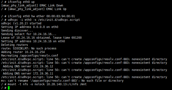
Figure 6-4 kernel_nfs_cmd
6.4 Common Third-Party Tools
6.4.1 iperf3
-
iperf3 server mode
./iperf3 -s -i 1
Options Description -s Server mode -i 1 Print echo interval (unit: seconds), here is 1 second -
iperf3 client mode
./iperf3 -c xxx.xxx.xxx.xxx -i 1 -t 36000 -b 95M
Options Description -c client mode xxx.xxx.xxx.xxx peer's IP address -i 1 Print echo interval, in seconds, here is 1 second -t 36000 Streaming time, in seconds, up to 86400 (24 hours) -b 95M Stream rate 95Mbits/sec
6.4.2 tcpdump
Tcpdump is a packet capture tool under Linux.
./tcpdump -s 0 -i eth0 -w /tmp/pkt.cap //Capture the packets of eth0 network card and cache them to pkt.cap
| Options | Description |
|---|---|
| -s 0 | Specify the packet capture size, 0 means no limit |
| -i eth0 | Indicate the connected interface, any indicates all interfaces |
| -w /tmp/pkt.cap | Mean the captured packets are written to the specified path. The file is .pcap |
6.4.3 ethtool
-
View eth0 network card information
ethtool eth0
-
Switch the eth0 network card speed and duplex mode
ethtool -s eth0 speed 100 duplex full
-
Enable/disable eth0 auto-negotiation
ethtool -s eth0 autoneg on/off
-
Enable Flow Control
ethtool -A eth0 rx on tx on
-
View eth0 packet receiving statistics
ethtool -S eth0
6.4.4 phytool
-
Read the value of phy reg
read IFACE/ADDR/REG
Options Description IFACE eth0 or eth1 ADDR Location on mdio bus REG Read phy reg eg: read eth0 addr0 reg2
phytool read eth0/0/2
-
Write value to phy reg
write IFACE/ADDR/REG <0-0xffff>
Parameters Description IFACE eth0 or eth1 ADDR Location on mdio bus REG phy reg written <0-0xffff> Value to write Eg: write the loopback bit of eth0
phytool write eth0/0/0 4000
6.5 Commonly used DEBUG nodes
6.5.1 dlist emac driver statistics node
Use cat dlist to view information such as emacs driver interruption/packet reception statistics.
/ # cat /sys/devices/virtual/sstar/emac0/dlist_info
RBQP_size=0x100
empty=0x100, hemac->rxBuffIndex=0x7f, u32RBQP_Addr=0x20a07f
0x000: 1111111111111111 1111111111111111
0x020: 1111111111111111 1111111111111111
0x040: 1111111111111111 1111111111111111
0x060: 1111111111111111 1111111111111111
0x080: 1111111111111111 1111111111111111
0x0a0: 1111111111111111 1111111111111111
0x0c0: 1111111111111111 1111111111111111
0x0e0: 1111111111111111 1111111111111111
max_rx_packet_count=4
max_tx_packet_count=1
IDX_CNT_INT_DONE=0
IDX_CNT_INT_RCOM=0
IDX_CNT_INT_RBNA=0
IDX_CNT_INT_TOVR=0
IDX_CNT_INT_TUND=0
IDX_CNT_INT_RTRY=0
IDX_CNT_INT_TCOM=0
IDX_CNT_INT_ROVR=0
IDX_CNT_JULIAN_D=67901
IDX_CNT_INT_TDLY=0
IDX_CNT_INT_TDTO=0
skb_tx_send=698
skb_tx_free=698
rx_duration_max=374
rx_packet_cnt=67967
tx_delay_pack_cnt=0
data_done=42
data_duration=41152
data_average=0
tx_pkt (duration)=1
tx_int (duration)=0
tx_int_dly (duration)=0
tx_int_to (duration)=0
rx_int_dly (duration)=976
rx_pkt (duration)=977
Hal_EMAC_TXQ_Mode=0
maxSG=2
6.5.2 phyStatusWR phy reads and writes debug nodes
-
Usage
/ # cat /sys/devices/virtual/sstar/emac0/phyStatusWR phy read & write: Usage: echo phy_r phyAddress > phyStatusWR echo phy_w phyAddress phyValue> phyStatusWR echo phyE_r phyId phyAddress > phyStatusWR echo phyE_w phyId phyAddress phyValues > phyStatusW -
eg
/sys/devices/virtual/sstar/emac0 # echo phy_r 0 > phyStatusWR
phy_r address[0] value[3100]
/sys/devices/virtual/sstar/emac0 # echo phy_w 0 1200 > phyStatusWR
phy_w address[0] value[1000]
/sys/devices/virtual/sstar/emac0 # echo phyE_r 1 0 > phyStatusWR
phyE_r id[1] address[0] value[3100]
/sys/devices/virtual/sstar/emac0 # echo phyE_w 1 0 0x1200 > phyStatusWR
phyE_w id[1] address[0] value[1000]
6.5.3 turndrv drives debug nodes
-
Usage
/sys/devices/virtual/sstar/emac0 # cat turndrv Usage: echo f10t > turndrv => set max_speed to 10M echo an > turndrv => set link mode to autonegotiatingn echo dir_on > turndrv => enable Dynamic Rx Interrupt echo dir_off > turndrv => disable Dynamic Rx Interrupt echo swing_100 [gear] > turndrv => swing 100M tx gear echo swing_10 [gear] > turndrv => swing 10M tx gear echo rx_imp [level] > turndrv => adjust rx impedance, range:-4 ~ 7 echo timing [is_rise] [delay_time] [duty_cycle] [phase] > turndrv -
f10t limits the maximum rate to 10Mbits/sec
 An auto-negotiation is required to switch to 10M

 / # echo f10t > /sys/devices/virtual/sstar/emac0/turndrv
 SPEED_10
 / # echo an > /sys/devices/virtual/sstar/emac0/turndrv
 phy_start_aneg
-
an performs auto-negotiation
 / # echo an > /sys/devices/virtual/sstar/emac0/turndrv
 phy_start_aneg
-
dir_on turns on RX DELAY to dynamically adjust the threshold
 / # echo dir_on > /sys/devices/virtual/sstar/emac0/turndrv
 rx_stats_enable: 1
-
dir_off Turn off RX DELAY dynamic adjustment threshold
 / # echo dir_off > /sys/devices/virtual/sstar/emac0/turndrv
 rx_stats_enable: 0
7. API Reference
EMAC has no external API
8. FAQ
Q1: "xxx could not connect to PHY" appears in the startup log, and the network cannot communicate
-
Check whether the RMII pin configuration in padmux.dtsi is turned on, and confirm whether there is any conflict in the pin configuration.
-
Confirm the reset timing of the phy used. If there is a reverse circuit, you need to add the "reset_reverse" attribute in the dts emac node, otherwise you need to remove the "reset_reverse" attribute. At the same time, you need to confirm whether the time to maintain the level meets the requirements of the phy.
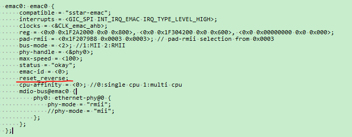
Figure 8-1 reset_reverse dts -
If the phy you are using is not provided by sstar, you need to contact the corresponding phy manufacturer to confirm whether a dedicated phy driver is needed.
-
Check whether the hardware wiring is correct, whether there is any wrong connection, poor soldering, short circuit, etc.
Q2: The device has a lot of packet loss and the network speed cannot be increased
-
Check whether the link mode of the device and the peer is consistent. You can use the "./ethtool eth0" command to view the current phy link mode.
-
Check whether the physical connection of the network cable is loose and whether the quality of the network cable itself is qualified.
-
Check whether the network environment is normal, such as whether the firewall is turned on, whether the transit equipment (router, switch) has a QoS policy that affects the bandwidth, etc. You can change to a direct connection environment for verification and troubleshooting (such as DUT directly connected to the PC).
-
Check whether the CPU load of the device is too large, so that the device cannot process network messages in time, resulting in packet loss.
-
Check the signal quality and adjust the phy-side drive capability by configuring the corresponding phy register.
Q3: If the network is not used, will retaining the EMAC module result in additional power consumption?
There will be no additional power consumption. As long as the network port is in the down state, EMAC clk will not be turned on. You can use the "ifconfig" command to check whether there is an open network port.