System Partition
1. System startup process
1.1. ROM CODE
The code executed after the CPU is powered on is called Rom code, which is fixed in the hardware. The function of Rom code is to read the IPL binary data stored at a specific address of the flash into SRAM and jump to the IPL execution.
When using Spi-nor flash and EMMC, Rom code will read the IPL code segment from flash address 0 and execute it; when using Spi-nand flash, the situation will be a bit complicated because of the possible bad blocks in the manufacturing process of Spi-nand flash.
When using Spi-nand flash, Rom code will read CIS information from address 0 of flash. CIS stores some basic attribute information of Spi-nand flash, such as Block size, Page size, etc. There are two key data in CIS: BLK PB0 and BLK PB1, which are the index values of Block. Rom code can find the location of IPL in flash through this value. As shown in the figure below, Rom code will first determine whether the Block pointed to by BLK PB0 is a bad block or there is ECC ERR. If three consecutive blocks are bad blocks or there are ECC ERR, BLK PB1 will be used instead. Similarly, starting from the Block pointed to by BLK PB1, three consecutive blocks will also be judged. If they are all bad blocks or there are ECC ERR, it cannot be started.

1.2. System startup phase
The system startup process can be divided into several stages, each with different functions. Before the Linux operating system is running, the startup sequence generally includes: Rom code, IPL, IPL_CUST, TF-A, and U-Boot. Each stage has its corresponding binary file stored in the flash, so they need to be managed in a partitioned manner during the startup process. In addition to Rom code, which can directly read the Block information where the IPL is located from the CIS and then jump to the IPL execution, the jumps between other different stages need to read the partition information of the next stage code from the partition table and then jump. The partition table of SStar is called PNI, which is contained in the CIS at the flash 0 address. This part will be introduced in detail later.
The following describes the specific role of each code in the startup process:
-
CIS
On Spi-nand flash, CIS is stored at address 0 of flash. On Spi-nor flash, CIS is stored after the IPL partition. CIS contains three parts: The first part is GCIS, which contains general information of flash. Its purpose is to make Rom code adapt to most types of flash and enable boot flow to enter IPL smoothly. The second part is called SNI, which stores information specific to various types of flash, such as block page count, block count, etc. The third part is called PNI (partition info), which stores partition information. The information in PNI is used for the IPL/IPL_CUST stage. When the Linux system is started, the partition information is replaced by U-Boot's mtdparts to follow the Linux native partitioning process. In mtdparts, except for the BOOT partition used to make the One bin part, which is different from that in PNI, other partition information must be equal to that in PNI. The difference is that you can see more specific distribution information from PNI than from the BOOT partition of mtdparts, such as the specific location of IPL/IPL_CUST/U-Boot.
-
IPL/IPL_CUST
After the CPU is powered on, the first thing to run is the Rom code. At this stage, the DDR has not been initialized, so the SOC provides an SRAM to execute a section of code we call IPL. Since the SRAM is very small, only about tens of KB, the code size of the IPL must be controlled within the size range of the SRAM. The IPL code mainly initializes the DDR, and only after the initialization is completed can the larger IPL_CUST code or U-Boot code be loaded.
IPL_CUST will be executed after IPL. It will initialize the hardware according to the current board configuration, such as customized GPIO pins, IIC configuration, etc. It will also access the env partition, obtain the BBM flag, and repair the BBM. BBM handles the correctable ecc inversion bit of the flash. IPL_CUST will finally decide which code to run next based on its compile-time configuration. It can choose to run U-Boot, TF-A, or Linux. In the fast start solution, IPL_CUST can skip the U-Boot stage and jump directly to Linux.
-
TF-A
TF-A (Trusted Firmware-A) originally refers to the low-level open source firmware code for ARM Cortex-A series chips. On the SStar platform, TF-A is only used as BL3-1, mainly to provide runtime services, that is, to provide exception vector table callback functions for entering and exiting EL3, and to provide PSCI function to control the on/off of the 4-core CPU core.
-
U-Boot
Native open source bootloader code.
-
RISC-V
In addition to a quad-core ARM Cortex-A35 CPU, the SigmaStar PCUPID series chips also have a RISC-V core. RISC-V runs the FreeRTOS system alone, and the system image is stored in the RISCVFW partition on the flash. The RISCVFW image will only be used in scenarios that include RISC-V.
1.3. Start Flow
First, briefly introduce the ARMv8 boot flow. In the ARMv8 architecture, ARM introduced Trust Firmware as an overall solution for security,
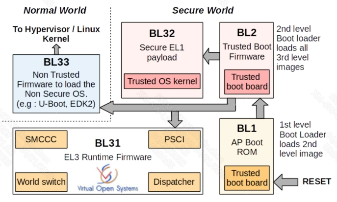
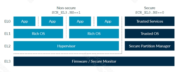
As shown in the figure. The ARM boot flow is BL1 → BL2 → (BL31/BL32/BL33). BL1, BL2, BL31, BL32, and BL33 each perform specific functions and run at different kernel exception levels.
BL1 (Boot Loader stage 1): BL1 typically runs code stored in the BootROM on the chip and has the highest execution privilege at EL3 level. Its main function is to validate BL2 Boot Firmware, complete loading, and transition control. It corresponds to the ROM Code in the platform.
BL2 (Boot Loader stage 2): The main role of BL2 is to initialize the storage media required by the platform, configure the MMU, validate BL31/32/33, and complete loading. BL2 still runs at the EL3 level and corresponds to the IPL in the platform.
BL31 (Boot Loader Stage 3-1): After BL2 loads BL31, it transfers control to BL31 (still running at EL3 level). It primarily provides initialization services for booting and the operating system. After initialization, BL31 loads BL32 and transitions to it. It corresponds to IPL/IPL_CUST in the platform.
BL32: This is the so-called Secure OS, such as OP-TEE (Open source Project Trusted Execution Environment).
BL33: This is the common Bootloader (U-Boot/UEFI), running at Armv8 EL2 level, and completes the boot process to run the Kernel. It corresponds to U-Boot in the platform.
Before the Linux kernel starts, the CPU will execute several sections of code:

You can select the boot process in the IPL_CUST stage through Flag. This Flag can be a certain env or the status of a certain gpio pin. Currently, the blue line flow is used by default during startup. If the Flag is true, the red line flow will be used to skip U-Boot. The main function of U-Boot is to upgrade the image and native mtd support.
6.6. EMMC UDA partition division
UDA partition design is as follows:
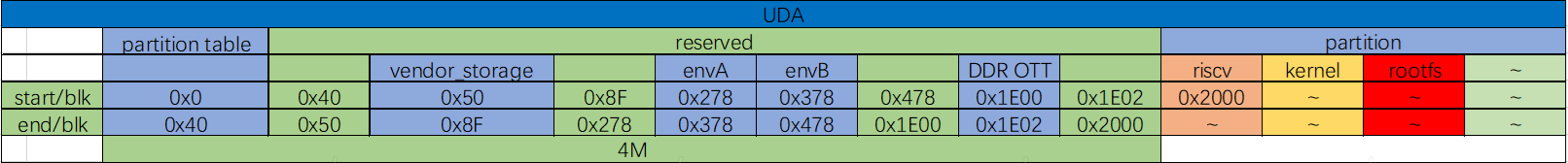
partition table:
The first block stores partition identification information, indicating that the created partition type is EMMC type. There are 63 blocks from 1 to 64, and each block stores the information of the corresponding partition created, including the partition name, starting address, and size.
reserved:
The reserve area is reserved for other purposes.
env:
The env area is divided out from the reserve area to store the environment variables required to start Linux. Its size can be divided according to actual needs.
partition:
Partition is where the partition data corresponding to the partition table is stored. By default, it starts from the 615424th block, but you can also modify the partition start offset by modifying the CONFIG_SSTAR_EMMC_PARTTION_START value of uboot. In order to avoid damaging DDR OTT data, this value cannot be less than 0x1E02. Because it needs to be aligned with the erase group, that is, 512K, the value of CONFIG_SSTAR_EMMC_PARTTION_START cannot be less than 0x2000. As shown in the figure above, the start address of UDA partition 1 is 0x2000 (the actual address should be based on the partition address set by the user, where partition 1 is riscv). The partition start offset plus the size of the first partition is the starting address of the second partition, and so on. A total of 63 partitions are allowed to store data.
In addition, uboot also supports reallocating all remaining emmc space to the last partition, namely the customer partition, but you need to manually turn on SSTAR_EMMC_PDB_RESIZE_CUSTOMER_PARTITION, otherwise the capacity will not be expanded by default.
1.4. One bin
The One bin function is to make the blue part of the booting stage in the above figure into a binary form when ALKAID is packaged. What you see during programming is a BOOT partition instead of a specific IPL/IPL_CUST/U-Boot partition.
Spi-nand, Spi-nor and EMMC all supports One bin, but the specific details will be distinguished, and the following chapters will introduce them in detail. The following table lists the composition of One bin in different systems:
| Boot Mode | boot.bin Composition |
|---|---|
| Linux + U-boot | IPL + IPL_CUST + TF-A + UBOOT |
| Linux + U-boot + RISC-V | IPL + IPL_CUST + TF-A + UBOOT + RISCVFW |
One bin integrates several different boot codes in the booting stage into a binary, which can simplify the complexity of partitioning in the bootloader stage and make it easier to maintain. At the same time, by splicing together different code binaries, the alignment requirements of the partition size can be ignored, thereby saving the binary size of the Nor flash boot code.
One bin is different from not One bin systems in blank chip programming. The bins and addresses for programming are as follows:
-
SPINAND
Burned bin Flash location Description cis.bin 0x0/0x20000 Burn both locations boot.bin 0x140000 -
SPINOR
Burned bin Flash location Description boot.bin 0x0 -
EMMC
Burned bin Flash location Description boot.bin 0x0
2. Partition Introduction
2.1. Flash partition preview
The partition table is saved in partition_layout.txt of the compiled output, as shown in the figure below. The partition configuration in the figure below may be different in different ALKAID defconfig. Please refer to the currently compiled code.
SPI-NOR partition table information:

SPI-NAND partition table information:
EMMC partition table information:
2.2. MISERVICE Partition
The contents of the MISERVICE partition are mounted to the root directory /config/. The files with bold fonts in the following table must keep the same path, otherwise the system may not start.
└── config
├── config.json ---->Save screen paramter information
├── iqfile
│ ├── imx307_iqfile.bin
│ ├── iqfile0.bin -> imx307_iqfile.bin ---->The underlying IQ bin, the content cannot be changed, but the path can be changed. For details, see "Sensor User Guide"
│ ├── iqfile1.bin -> imx307_iqfile.bin
│ ├── iqfile2.bin -> imx307_iqfile.bin
│ ├── iqfile3.bin -> imx307_iqfile.bin
│ └── isp_api.xml
├── modules ---->Path to save system ko
│ └── 5.10
├── lib ---->Path to save so
├── dla
│ ├── ipu_lfw.bin
│ ├── det ---->Recognition model of human face and shape
3. CIS Partition Structure
As can be seen from the above introduction, the partition of CIS is divided into three parts, starting from the 0 address of the flash, it is GCIS, PNI and SNI respectively.
3.1. PNI
Partinfo.pni is dynamically generated by the tool pnigenerator, and will be saved as a separate file in image/boot/ after compilation.
Code and compile:
-
Source path of the pnigenerator tool
project/image/makefiletools/src/pnigenerator/pnigenerator.c
-
Compile with gcc on the server
gcc pnigenerator.c -Wall –o pnigenerator
Example of use:
pnigenerator -c 256 -s 0x10000 -a "0xc000(IPL),0x6000(CIS),0x9000(IPL_CUST),0x9000(TF_A),0x32000(UBOOT),0x1000@0x6F000(ENV)" -m "ipl cis ipl_cust tf_a uboot" -t "0x340000(KERNEL),0x270000(rootfs),0x50000(MISC),0x490000(miservice),0x4E0000(customer)" -o /home/users/project/image/output/images/boot/partinfo.pni
Parameter definition:
-r: Read the partitions in the target PNI file and print.
-c: The sum of the BLOCKs of FLASH occupied by all partitions.
-s: FLASH is the data size of a BLOCK, in bytes.
-a: A collection of BOOT PART partitions, expressed in the syntax format of mtdparts
-t: A collection of SYS PART partitions, expressed in the syntax format of mtdparts
-o: Filename and path that generates the PNI file
The PNI file is not statically stored in the packaged project. It is determined according to the compilation configuration used by the user. The pnigenerator tool generates a bin file according to the parameters of the incoming configuration partition.
PNI generates file project/image/output/images/boot/partinfo.pni from the information passed into the partition through the "-a", "-t" parameters.
3.2. SNI
The path where SNI is stored on the board of ALKAID:
-
SPINAND
project/board/$(CHIP)/boot/spinand/partition/flash_list.sni
-
SPINOR
project/board/$(CHIP)/boot/nor/partition/flash_list.nri
3.3. GCIS
GCIS is a special SNI, it contains general FLASH initialization parameters, which are used to read the parameters used to start FLASH for the solidified code in the ROM CODE. The ultimate purpose is to read the data of IPL, so that the BOOT stage starts to in IPL.
The path where SNI is stored on the board of ALKAID:
-
SPINAND
project/board/$(CHIP)/boot/spinand/partition/flash.sni
-
NOR
project/board/$(CHIP)/boot/nor/partition/flash.nri
3.4. CIS Partition Data Structure
The partition of CIS is spliced by the above-mentioned GCIS, PNI and SNI according to a specific method, and is dynamically generated by the Makefile script.

The figure above shows the structure of the CIS data. Since GCIS and PNI are both smaller than a PAGE, they each occupy a PAGE space. Since all FLASH information is saved in SNI_LIST, it will be appended to the back of PAGE1. Please note that the PAGE size of NOR FLASH and SPINAND FLASH is not necessarily 2k or 4K, it is related to the specification of FLASH, please refer to the SPEC of FLASH for details.
The size of the PAGE can be defined according to cis$(PGSIZE) defined in the partition's config script.
In the process of making the burning script of the partition, the bin making and burning of the CIS partition is also one of the links. The whole making process will be introduced later. The making of the CIS bin is executed in the target cis_nofsimage in project/image/image.mk .
After the production is completed, the cis.bin generated in project/image/output/images/ contains the three contents of GCIS/PNI/SNI.
4. Partition Configuration
4.1. Precautions before partition configuration
Whether it's a partition on spi-nor flash, or a partition on spi-nand flash. They can be classified into two categories, one is the boot that is not recommended to be changed, and the other is the sys that can be changed. The partition changes introduced in this chapter are all in the sys part, including how to configure the script to change the partition order, how to package Partition, how to generate a burning script, if the customer has his own set of packaging and burning process, you don't need to care about this chapter. It is important to note that in the previous chapter, there are specially marked files in the miservice partition that need to be placed in the specified path before the system can run. Therefore, when making a partition, be sure to create /config/ in the root directory and put the relevant file in this path.
4.2. Script configuration
Partition change is divided into three parts: partition creation, packaging and partition burning script creation. In the two branches of the following flowchart, the left side is the partition creation and packaging process, and the right side is the partition burning script creation process. The partition burning script only supports the tftp upgrade script.

4.2.1. Partition Configuration Script
Script path for partition configuration:
project/image/config/general/xxx.partition.config
This is the general partition configuration information script. All the codes related to partition adjustment are implemented in this config file. There will be many copies of this config file. Each different chip, spinand partition or spinor partition will have its own partition config file, where all customized changes are integrated.
Through build config, you can find out what is the partition config file used by the project, and the defined variable is IMAGE_CONFIG.
In this configuration script, the variable IMAGE_CONFIG can find the corresponding partition configuration script used.
In the config script file, each partition is represented by a set of variables, as shown in the following figure:

Please refer to the previous chapter on the CIS partition structure. The CIS partition is very special. It stores a set of specified partition configuration raw data. This is a special partition. The special partition is generated by special instructions.
Partitions are divided into those with a file system and those without a file system. Their packaging and programming scripts are completely different. The creation of a partition image file with a file system can be handled uniformly by tools, while a partition without a file system needs to be targeted for Each partition is processed separately.
Some of the partitions used by the public version are introduced above , such as the miservice partition, which can be configured as a read-only squashfs file system, or can be made into jiffs2 or ubifs. All the partitions used by the public version are used by the xxx.mk script. Fill in the file content inside the image file. Obviously, miservice.mk will copy all the ko and so required by mi to the target folder, and rootfs.mk will copy the files needed inside the root file system to The target folder, such as rootfs.mk, will copy the busybox tool required by linux.
Example of miserive partition configuration:

4.3. Partition location change
In the configuration of the CIS partition, the variables cis$(BOOTTAB0), cis$(BOOTTAB1), and cis$(SYSTAB) are used to configure the partition information.
cis$(BOOTTAB0) and cis$(BOOTTAB1) are used to specify its A-B partition in one bin production. This method will identify in PNI whether the BOOT used in it is active, currently in spi-nand partition, A-B partition is introduced, of which BOOTTAB0 is the active partition. When BOOT is abnormal in programming or has a bad block, it will jump directly from BOOT to the backup partition of BOOT_BAK, and re-identify the active partition in PNI, it will automatically run to the active partition at the next startup.
BOOTTAB0, BOOTTAB1, and SYSTAB are the definitions of partition tables. The syntax format used by it is supported by mtdparts. The format can be written as:
partition0_size ( partition0_name), partition0_size(partition0_name),…
For example, the description format of the following CIS and IPL partitions:
0x14000 (CIS) ,0x60000 (IPL)
Each partition is separated by commas. If the starting position of the partition is not specified, it will be counted from the first partition, and the partition will start from the 0 address of FLASH by default. If you need to configure from the specified location of the partition, follow the following syntax format:
partition0_size@offset(partition0_name)
After specifying the starting position of the partition, if the partition added after this partition does not specify its position, its starting position will increase one by one after the current partition.
If the current partition is the last one in the partition table, a more convenient method can be used to adapt the size of the partition.
For example, the UBI partition of spinand, at the end of the partition table, it can be expressed as:
xxxx( xxxx), xxxx(xxxx),-(UBI)
The logic of partition table parsing will adapt to the size of UBI with reference to the size of the current flash configuration.
The modification of the partition location is to change the location of the partition in the three variables cis$(BOOTTAB0), cis$(BOOTTAB1), and cis$(SYSTAB) . Generally, the partition of the BOOT part will not change its position, and it is more common for SYSTAB to change.
4.4. Add, modify, delete jiffs2 partition
On spinor's flash, jiffs2 is generally used as the file system of the readable and writable partition. The relevant configuration of the customer partition is defined as follows:
customer $(RESOURCE) = $(OUTPUTDIR)/customer
customer $(FSTYPE) = jffs2
customer $(PATSIZE) = 0x5C0000
customer $(MOUNTTG) = /customer
customer $(MOUNPTT) = mtd:customer
customer $(OPTIONS) = ro
customer $(MTDPART) = $(customer$(PATSIZE))(customer)
customer $(OTABLK) = /dev/mtdblock6
customer$(RESOURCE) : The folder where the source files to be packaged are located. The contents of this folder are filled by the customer.mk script.
customer$(FSTYPE) : The filesystem type of the package.
customer$(PATSIZE) : partition size, in bytes.
customer$(MOUNTTG) , customer$(MOUNTPT), customer$(OPTIONS) : The path and parameters that the partition needs to mount after the board is up. These parameters are handled in rootfs.mk.
customer$(OTABLK) : The path to the upgrade device node required for OTA upgrade packaging.
4.4.1. Modifications
To modify a partition, generally modify the file system and partition size.
After modifying the file size, carefully check whether the cumulative size of all partitions exceeds the flash size.
You can check whether the partition size overflows in partition_layout.txt.
4.4.2. Adding partitions
aaa $(RESOURCE) = $(OUTPUTDIR)/aaa
aaa $(FSTYPE) = jffs2
aaa $(PATSIZE) = 0x6B0000
aaa $(MOUNTTG) = /aaa
aaa $(MOUNPTT) = mtd:aaa
aaa $(OPTIONS) = rw
aaa $(OTABLK) = /dev/mtdblockX
-
Suppose a partition named aaa is added, and then configure its size and other information.
-
After the partition-related variables are configured, specify the location where they are placed in cis$(SYSSTAB) = "xxx".
-
Append "aaa" to the variable "IMAGE_LIST".
-
Append "aaa" to the variable "USR_MOUNT_BLOCKS" representing the node to be mounted.
-
The logic of copying files to $(OUTPUT)/aaa needs to be added to the script before the partition is packaged.
4.4.3. Deleting partitions
Follow the operations for adding partitions and do the reverse.
4.4.4. Burn script
The system will automatically generate it according to the partition configuration in script.mk.
4.5. Add, modify, delete squashfs partition
The partition change of Squashfs is similar to the change of the jiffs2 partition, mainly different in xxx$(FSTYPE). Except for the special partition of rootfs, the miservice partition is made into squashfs:
miservice $(RESOURCE) = $(OUTPUTDIR)/ miservice/config
miservice $(FSTYPE) = squashfs
miservice $(PATSIZE) = 0x180000
miservice $(MOUNTTG) = /config
miservice $(MOUNTPT) = /dev/mtdblock3
miservice $(OPTIONS) = ro
Like the jiffs2 partition, the system will automatically generate a burning script in script.mk according to the partition configuration.
4.6. Add, modify, delete ubifs partition
UBIFS partitions are generally used on spinands as a readable and writable partition file system.
All partitions of UBIFS belong to a sub-partition in the mtd block of UBI. A common UBI partition variable is set as follows:
miservice $(RESOURCE) = $(OUTPUTDIR)/miservice/config
miservice $(FSTYPE) = ubifs
miservice $(PATSIZE) = 0xA00000
miservice $(MOUNTTG) = /config
miservice $(MOUNPTT) = ubi0:miservice
miservice $(OPTIONS) = rw
Unlike the jiffs2 partition change method, the ubifs partition does not need to add mtdpart information, that is, there is no need to add the partition location in cis$(SYSTAB) = xxx.
4.7. Add, modify, delete LFS/FWFS partition
The benefit of Littlefs or Fwfs partitions is that they are accessible in uboot/linux/rtk.
The MISC partition uses files related to storing system configuration scripts, such as screen parameter information:
misc $(RESOURCE) = $(OUTPUTDIR)/misc
misc $(FSTYPE) = lfs
misc $(PATSIZE) = 0x60000
misc $(MOUNTTG) = /misc
misc $(MOUNTPT) = /dev/mtd4
misc $(OPTIONS) = rw
misc $(MTDPART) = $(misc$(PATSIZE))(MISC)
misc $(OTABLK) = /dev/mtdblock4
For the modification method, please refer to squashfs or jffs2.
4.8. Multiple UBI Partitions
The location of the ubi partition is planned in mtdparts. In most cases, only one ubi partition is used. Generally, it is defined with -UBI at the end of the sys part. In the UBI partition, it has its own sub-partition definition, which is called volume. Can be defined as a volume of the UBI partition. The config script can be configured into multiple UBI partitions, and each partition can be configured with its own volume.
If there are multiple ubi partitions, they can be called ubia or ubib, such as the following definitions:
ubia $(PATSIZE) = 0x1400000
ubia $(MTDPART) = $(ubia$(PATSIZE))(ubia)

ubib $(MTDPART) = -(ubib)
Define the location of the above ubi partition in the sys part:
cis $(SYSTAB) = xxx,xxx,$(ubia$(MTDPART)),$(ubib$(MTDPART))
Add the configuration of two ubi partitions to bootargs, and the kernel startup will initialize the ubi partitions in this order:
ubi.mtd=ubia ,2048 ubi.mtd=ubib,2048
In the definition of volume, the variable BlockName$(OPTIONS) is used to define which ubi partition it is created in. For example, the miservice partition is created in ubia:
miservice $(OPTIONS) = ubia
Note here that parameters should be used in the place of ubi volume mount to indicate which ubi node is used, such as:
miservice $(MOUNPTT) = ubi0:miservice
This serial number is judged according to the order of multiple ubi.mtd=xxx defined in bootargs.
4.9. Ubinize
ubinize is a function provided when ubi partition is packaged. It can convert volume files generated by ubi partition into flash image files. Therefore, when burning, directly use flash read/write to burn the ubi partition, instead of using the ubi command to burn the volume.
In configuration, first define a ubi partition name. The ubinize function requires the mtdparts partition name of ubi. It must start with a lowercase "ubi" followed by a serial number.
For example, there are multiple ubi partitions, ubia ubib, to be in the form of images. Add ubia and ubib to IMAGE_LIST. The addition is to automatically generate the upgrade script of ubi image, not the upgrade script of ubi volume.
Use the variables provided by the packaging script:
BlockName$(UBIVOLID) and BlockName$(OPTIONS)
E.g:
miservice $(UBIVOLID) = 0

miservice $(OPTIONS) = ubia
The above shows that in the process of ubinize creating an image, miservice is the 0th volume in the ubia partition image.
When multiple volumes are configured in the same ubi partition, the configuration of each volume should be arranged according to the UBIVOLID serial number.
4.10. Special Partition Handling
KERNEL, uboot, IPL, logo, cis and other partitions are special partitions. These partitions do not have a special file system, so they cannot be centrally processed in the Makefile script, and must be specially processed. Therefore, adding a special partition requires a clear understanding of the following two steps (here is the kernel partition):
-
In image.mk, you need to write the script command for partition packaging
kernel_nofsimage: @echo [[$@]] cp -rvf $($(patsubst %_nofsimage,%,$@)$(RESOURCE)) (IMAGEDIR)/$(patsubst %_nofsimage,%,$@) -
Write the command generated by the partition burning script in script.mk
kernel_$(FLASH_TYPE)__script:
    @echo "# <- this is for comment / total file size must be less than 4KB" > $(SCRIPTDIR)/[[kernel.es
    @echo tftp $(TFTPDOWNLOADADDR) kernel >> $(SCRIPTDIR)/[[kernel.es
    @echo $(FLASH_PROBE) >> $(SCRIPTDIR)/[[kernel.es
    @echo $(FLASH_ERASE_PART) KERNEL >> $(SCRIPTDIR)/[[kernel.es
    @echo $(FLASH_WRITE_PART) $(TFTPDOWNLOADADDR) KERNEL \$${filesize} >> $(SCRIPTDIR)/[[kernel.es
    @echo "% <- this is end of file symbol" >> $(SCRIPTDIR)/[[kernel.es
    @echo kernel-image done!!!
5. Partition configuration customization interface
5.1. Customization rules for partition configuration
In the previous chapter, the changes to the partition configuration were mainly focused on the config script file. If the partition configuration script provided by the public version cannot meet the needs of a new platform. Please add your own config script.
In principle, the following scripts are not allowed to be modified in the scripts packaged by partition:
image/Makefile
image/image.mk
image/scripts.mk
image/packaging/common/rootfs.mk
image/packaging/common/ramdisk.mk
image/packaging/common/miservice.mk
image/packaging/common/customer.mk
image/config/general/nor.squashfs.partition.config      ->   Nor flash rootfs is squashfs
image/config/general/spinand.squashfs.partition.config   ->   Spinand flash rootfs is squashfs
image/config/general/emmc.ext4fs.partition.config    -> Emmc rootfs is ext4fs
At present, the public version provides some interfaces to provide customized changes. You can add some variables to the block definition of each partition, so that you can insert some customized instructions during the upgrade:
-
BlockName$(BLKENV)
In the config file, you can add the env to be written to each partition block during the upgrade as required. This env is compatible with the writing of tftp/usb/sd/ota during the upgrade. For example, the kernel will finally write its own image data size to the env:
kernel $(BLKENV) := kernel_file_size $$(printf 0x%x `stat -c "%s" $(kernel$(RESOURCE))`)\n
kernel $(BLKENV) += recovery_file_size $$(printf 0x%x `stat -c "%s" $(kernel$(RESOURCE))`)
-
BlockName$(CUSMK)
Add the content of each partition as required to generate the script whether to use a customized .mk file, if not defined, use the default script. (default script: rootfs.mk/miservice.mk/ramdisk.mk/misc.mk)
-
BlockName$(CUSCMD)
Each partition block inserts its own script directives after the upgrade, defining its directives.
6. ONE BIN
6.1. ONE BIN partition
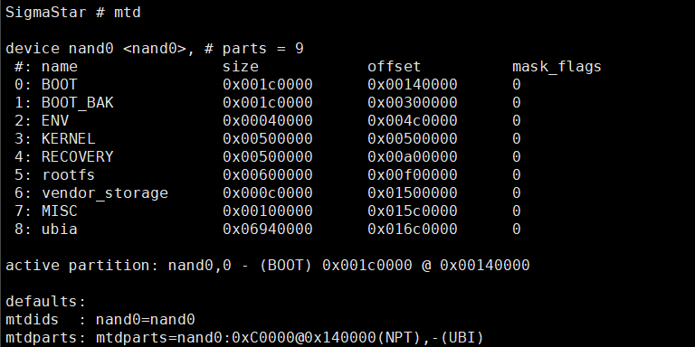
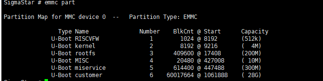
The ONE BIN function is based on the ALKAID packaging script to merge the BOOT PART partitions into one bin through the dd command. From the perspective of uboot and linux kernel, you can enter the command mtdpart or emmc part in uboot to see the current partition plan, which is different from pni. It is the part of BOOT PART. The entire BOOT PART no longer refines the internal partition, but consists of a BOOT partition, as shown in the following figure:
NOR FLASH Partition:
SPINAND FLASH Partition:

EMMC Partition:
After the ONE BIN is packaged, a boot.bin will be generated under output/images/. The boot.bin is stitched from the image of ipl/ipl_cust/uboot, and the nor flash will be additionally added with the cis partition.
6.2. BOOT partition of SPINAND
On the nand flash, BOOT0/BOOT1 belongs to the A/B partition, and the ROM code is started from the BOOT0 partition by default. If an ECC ERROR occurs in the BOOT0 partition or a bad block is encountered, it will jump to the BOOT1 partition, and after the next boot, it is enabled from the BOOT1 partition by default, which ensures that during the upgrade process, the BOOT part establishes a set of backup mechanisms to avoid the inability to enter the UBOOT cmd line after the upgrade of BOOT fails.
As mentioned above, the ONE BIN part is spliced with the dd command, and the specific composition is as follows:

The orange part in the above figure represents the size of the partition in the MTD PART, boot.bin represents the actual size of one bin, and the purple part represents the layout in this part of the pni.
The image of IPL/IPL_CUST generally does not exceed the size of one block, so they and their Backup each occupy the size of 3 blocks, and this size is fixed.
The data of UBOOT occupies the size of 2 blocks. Since uboot is often customized, the size of uboot's image may change. Therefore, configuring 2 blocks cannot guarantee all situations. If you want to modify it, please modify the uboot$(DATASIZE) = 0x40000 in the config file.
6.3. SPINAND BOOT Partition Bad Block Handling
4 GAPs of BLOCK are reserved on top of UBOOT. This part is forcibly reserved in the config file. These 4 BLOCKs are to make full use of the BK BLKs of IPL and IPL_CUST (they each have two backups, which add up to 4). Mandatory reservation code:
uboot $(PATSIZE) = $(call sum, $(uboot$(DATASIZE)) $(call multiplyhex, $(FLASH_BLK_SIZE), 4))
The purpose of the reservation is to handle the case of bad blocks. As can be seen from the above figure, the BOOT partition of MTD PART is 4 blocks larger than the boot.bin to be burned. When using tftp to burn or burn the code with a burner, if a bad block is encountered, the data will be automatically Write to the next block, then the data after the current position will be displaced as a whole.
Assuming that a bad block occurs at the location of IPL_CUST DATA, it will look like this after burning:

All data after IPL_CUST is shifted by one block, then the data in uboot will also be shifted by one block, and GAP will be occupied by one block. In the absence of bad blocks, the entire boot partition allows a maximum of 4 blocks of bad blocks. These 4 bad blocks are not arbitrary, and it is good to have at least one block in the IPL/IPL_CUST partition. If there are more than 4 blocks or the above conditions are not met, it will jump to the BOOT1 partition to ensure smooth startup.
6.4. BL0 PBA/BL1 PBA flags of SPINAND
After using the tool SpiNandInfoEditor.exe to open flash.sni or flash_list.sni, you will see the following fields:

These two fields are used to find the IPL partition for the rom code. The sni file found in ALKAID/project/board is filled with 0 by default, and the unit is block count, which means that the rom code finds IPL0 and IPL1 from the default address. The default address is IPL0: 0x140000, IPL1: 0x1A0000. Obviously it does not match the current partition configuration, so in the process of making cis.bin, the shell script will be used to fill in the correct values of BL0 PBA and BL1 PBA in flash.sni and flash_list.sni, which corresponds to block offset of the first address on flash in BOOT0/BOOT1 partition.
6.5. BOOT partition of SPINOR
SPINOR currently does not have A/B partitions by default. The BOOT part is different from SPINAND. The BOOT partition of SPINOR includes CIS, and the BOOT partition starts from address 0. The structure diagram of the BOOT partition is as follows.

Since SPINOR does not need to deal with bad blocks, IPL and IPL_CUST do not have backup blocks. The partition in the boot part needs to pay attention to the alignment of the partition's first address, end address and partition size. The reason for 4k alignment is to save space. In boot, IPL/IPL_CUST/UBOOT/CIS partition first address and partition size must be aligned with a page of nor flash, page size is 4k, ENV partition is not in BOOT partition, but it requires the end address of ENV partition to be aligned with the size of a block size in nor flash, generally 64k, then according to the layout in the figure below, there will be a GAP between UBOOT and ENV to ensure this alignment requirement. The function of this GAP is different from that of spinand. In addition to ensuring alignment requirements, it also has a function, that is, the buffering mechanism that is used to deal with the data change of the data part of UBOOT/IPL/IPL_CUS, which leads to the change of the internal partition of the PNI. Its purpose is to ensure that even if these partitions change in PNI, the BOOT partition and env partition of MTD are unchanged. Thereby, a larger amount of change is reserved for the ota upgrade BOOT (the main reason is that the ota upgrade partition cannot be changed).
The partition size of IPL/IPL_CUST/CIS/UBOOT in the partition of NOR flash is automatically 4k aligned in the script. The user only needs to adjust the size of the BOOT PARTITION of MTD, thereby increasing or reducing the GAP effect.
The size of BOOT is limited. Its size plus the partition size of ENV must be aligned with the block size. The variables that set its size are:
boot $(PATSIZE) = 0x4F000
6.6. EMMC UDA partition division
UDA partition design is as follows:
partition table:
The first block stores partition identification information, indicating that the created partition type is EMMC type. There are 63 blocks from 1 to 64, and each block stores the information of the corresponding partition created, including the partition name, starting address, and size.
reserved:
The reserve area is reserved for other purposes.
env:
The env area is divided out from the reserve area to store the environment variables required to start Linux. Its size can be divided according to actual needs.
partition:
Partition is where the partition data corresponding to the partition table is stored. By default, it starts from the 615424th block, but you can also modify the partition start offset by modifying the CONFIG_SSTAR_EMMC_PARTTION_START value of uboot. In order to avoid damaging DDR OTT data, this value cannot be less than 0x1E02. Because it needs to be aligned with the erase group, that is, 512K, the value of CONFIG_SSTAR_EMMC_PARTTION_START cannot be less than 0x2000. As shown in the figure above, the start address of UDA partition 1 is 0x2000 (the actual address should be based on the partition address set by the user, where partition 1 is riscv). The partition start offset plus the size of the first partition is the starting address of the second partition, and so on. A total of 63 partitions are allowed to store data.
In addition, uboot also supports reallocating all remaining emmc space to the last partition, namely the customer partition, but you need to manually turn on SSTAR_EMMC_PDB_RESIZE_CUSTOMER_PARTITION, otherwise the capacity will not be expanded by default.
6.7. ONE BIN SPECIAL ATTENTION
If the partition configuration of ONE BIN needs to be modified, please read this chapter carefully. Only uboot$(DATASIZE) of spinand and boot$(PATSIZE) of spinor can be appropriately modified to deal with the image file size change of IPL/IPL_CUS/UBOOT, please contact FAE for confirmation after modification. If the modification is improper, it is easy to cause the problem that the BOOT cannot be started in the production process.
If the packaging process does not refer to our company's ALKAID, pay special attention to the BL0 PBA and BL1 PBA in spinand's sni_list and gcis need to fill in the correct value according to the current BOOT0/BOOT1 position, or after confirming that the BOOT partition is the same, use the partition layout and boot.bin of BOOT compiled by ALKAID.
If you need to make your own boot.bin, please refer to the instructions in this chapter. For details, please refer to the Makefile function updatecis in the script image.mk, and the targets cis_nofsimage and boot_images.