RISVC_PWM USER GUIDE
REVISION HISTORY
| Revision No. | Description |
Date |
|---|---|---|
| 1.0 | 04/09/2025 |
1. OVERVIEW
The PWM (Pulse Width Modulation) module is used to generate pulse width waveforms. It can change the output current and voltage by changing the frequency and duty cycle to achieve functions such as controlling the motor speed and dimming the LCD screen. The SigmaStar PWM module also has a Group function (divided into sync, round, hold, stop), that is, every 4 or 6 channels of PWM can be bound into a group to achieve 4 or 6 channels of PWM synchronous generation or stop.
The relationship between devices and hardware groups is shown in the table below:
| PWM Group | bank addr | Channel |
|---|---|---|
| HW PWM group0 | 1119H | channel 0 ~ 3 |
| HW PWM group1 | 111AH | channel 4 ~ 7 |
| HW PWM group2 | 111CH | channel 8 ~ 11 |
| HW PWM group3 | 112BH | channel 12 ~ 16 |
| HW PM PWM group0 | 1AH | pm channel 0 ~ 1 |
2. Key Words
sysdesc:
RTOS files used to describe the hardware attributes of peripherals. The attribute values contained in peripheral nodes can be used for peripheral configuration, similar to Linux device tree files.
padmux:
Pin multiplexing is used to connect the functional pins of modules to specific external pins, establishing signal connections.
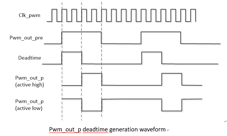
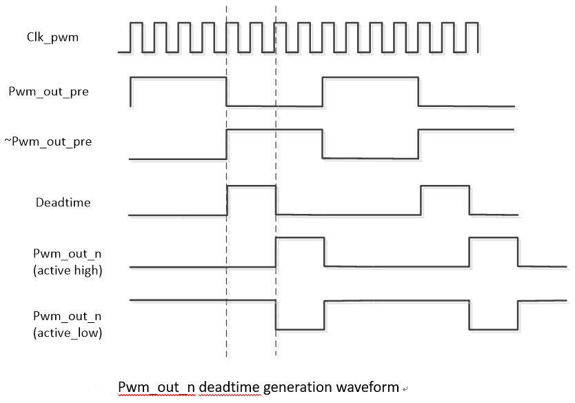
Dead Time:
The PWM dead time refers to the time interval between two adjacent output signals during the PWM signal switching process. It is used to prevent power switching devices (such as MOSFET or IGBT) from being turned on at the same time during the switching process, thereby avoiding short circuits and damage.
3. Function description
3.1. Overview
-
The number of channels supporting PWM is 20, of which channels 0~17 support joining their own groups, and channels 18~19 do not support the group function. For details, see Corresponding Relationship Between Group and Channel.
-
PWM channels 12~17 support Dead Time setting and brake function with the maximum setting value of (OSCCLK / 0x3FF). For example, if OSCCLK = 12MHz, the range is 0~85250ns.
-
Support double buffer to prevent the generation of erroneous waveforms, that is, the waveform will wait for the current waveform to be fully generated before updating.
-
Support shift function, that is, the waveform can have its phase set; the phase will affect the duty cycle, with the actual duty cycle = set duty cycle - phase
-
Support sync function, that is, the PWM in the group generates waveforms at the same time, generally a group will contain 4 channels of PWM.
-
Support round function, that is, the PWM in the same group will stop after generating a specific number of pulses.
-
Support hold function, that is, the PWM in the same group will pause after completing the waveform of the current cycle, which is often used to change the setting of the waveform, and the high and low levels within the pause time can be set.
-
Support stop function, that is, the PWM in the same group will stop urgently.
3.2 Frequency and Duty Cycle
-
Frequency
The number of times a signal changes from high level to low level and then back to high level per second.
-
Duty cycle
The ratio between the duration of high level and the duration of low level.
-
Example description
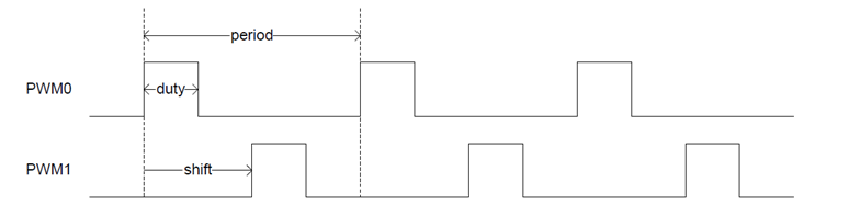
Assuming that the OSCCLK frequency of PWM is 12M, the frequency range that can be set is: 0.0007Hz~6MHz;
Set PWM0 and PWM1 to waveforms with a frequency of 120Hz and a duty cycle of 25%, and PWM1 has a phase shift of 180° relative to PWM0, then the parameters are configured as follows:
period duty shift PWM0 120Hz 25% 0% PWM1 120Hz 75% 50% Channels 0~17 support OSCCLK(Hz): 86M, 24M, 12M, 6M, 3M, 1.5M, 750K;
Channels 18~19 support OSCCLK(Hz): 12M, 6M, 3M;
The operating frequency range is (OSCCLK/2) to (OSCCLK/2^34).Actual working frequency range is as follows:
clk-freq PWM freq range 86MHz 0.0050Hz ~ 43MHz 24MHz 0.0013Hz ~ 12MHz 12MHz 0.0007Hz ~ 6MHz 6MHz 0.00035Hz ~ 3MHz 3MHz 0.00017Hz ~ 1.5Mhz 1.5MHz 0.000087Hz ~ 750KHz 750KHz 0.000044Hz ~ 375KHz The generated waveform is as follows:
3.3. Normal Precision Mode
If Support high precision calculation is not enabled in config, normal precision mode is used. In this mode, the unit of period of PWM is Hz, and the unit of duty cycle is percentage.
Assume that the frequency of PWM0 is set to 10000HZ and the duty cycle is 50%, then:
period = 10000
duty cycle = 50
3.4. High Precision Mode
When the Support high precision calculation option is enabled in config, the high precision mode is used. In this mode, the period and duty_cycle of PWM are configured in ns, so the period and duty cycle values must be calculated first.
Assuming that the PWM0 frequency is set to 10000.5HZ and the duty cycle is 49.5%, then:
period = 10^9 ÷ 10000.5 = 99995
duty cycle = 99995 * 49.5% = 49498
It can be seen that the advantage of high precision mode is that parameter settings support decimals.
3.5. GROUP Related Concept
3.5.1 Sync Mode
The sync mode can add each pwm channel to its own Group to achieve the purpose of controlling multiple PWMs at the same time. A Group has 4 pwm channels, and the corresponding relationship between Group and channel is as follows:
| Group | Group Member |
|---|---|
| Group0 | PWM0, PWM1, PWM2, PWM3 |
| Group1 | PWM4, PWM5, PWM6, PWM7 |
| Group2 | PWM8, PWM9, PWM10, PWM11 |
| Group3 | PWM12, PWM13, PWM14, PWM15, PWM16, PWM17 |
3.5.2 Hold Mode
The Hold function of the group will stop after the PWM completes the waveform of the current cycle and trigger an interrupt. At this time, the configuration of each channel waveform can be changed to keep synchronization. After the modification is completed, the hold function will be turned off and the PWM will regenerate a new waveform. Each group has its own independent hold function.
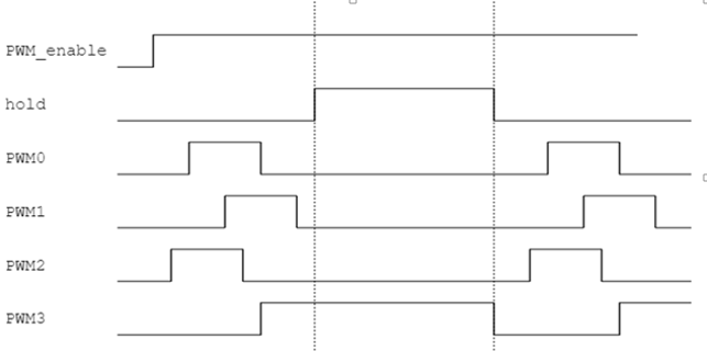
3.5.3 Round Mode
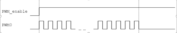
The round function will stop after all channels in the same group complete a certain number of pulses. Each group has its own independent round function.
3.5.4 Stop Mode
The stop function can stop the PWM in the current group immediately (without waiting for the current cycle to complete) and maintain the level at the end. Each group has its own independent stop function.
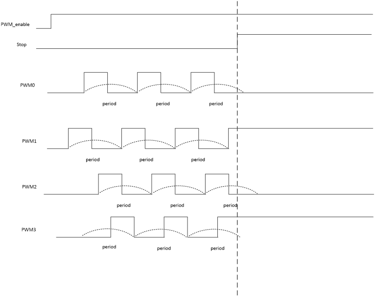
Note: It is not recommended to set the stop time to be too long, especially when the level maintained after PWM stops is high.
3.6. Dead Time
Dead Time is generated based on two complementary signals. The positive signal generates a delay based on the relative rising edge of the PWM clock, and the negative signal generates a delay based on the relative falling edge of the PWM clock.
4. RTOS USAGE INTRODUCTION
4.1. DRIVER PATH
sc/driver/sysdriver/pwm/drv/pub/drv_pwm.h
sc/driver/sysdriver/pwm/drv/src/drv_pwm.c
sc/driver/sysdriver/pwm/drv/src/drv_pwm_test.c
sc/driver/sysdriver/pwm/hal/chipname/src/hal_pwm.c
sc/driver/sysdriver/pwm/hal/chipname/inc/hal_pwm.h
sc/driver/sysdriver/pwm/hal/chipname/inc/hal_pwm_cfg.h
4.2. CONFIG Configuration
#make menuconfig

# Feature_Name = [DRV] PWM driver support
# Description = PWM driver support
# Option_Selection = TRUE, FALSE
CONFIG_PWM_SUPPORT = TRUE       //Enable the PWM driver
CONFIG_SSTAR_PWM_DDT = TRUE     //Enable the dead time function
CONFIG_SSTAR_PWM_EXTEND = TRUE  //TRUE: High precision mode, FLASE: Low precision mode
4.3. SYSDESC Configuration
The file chipname_xxx.sys is used to describe the hardware attributes of peripherals. The attribute values contained in the peripheral node can be used to configure the peripherals, similar to the Linux device tree. The file is located in sc/driver/sysdriver/sysdesc/hal/chipname/pub. The following takes pwm12 as an example:
<pwm12>
    [reg_u32_u16] 0x1F205600 0x40;
    [interrupts_u32] INT_IRQ_PWM_GROUP3;
    [camclk_u16] CAMCLK_pwm;
    [group_u32] 3;
    [spwm_group_u32] 0xFFFF;
    [clk_level_u8] 0;
    [ddt_reg_u32] 0x1F203600;
    [idle_status_u8] 0, 0;
    [padmux_u16] PINMUX_FOR_UNKNOWN_MODE;
    [status_u8] 1;
The attributes supported for configuration in the pwm driver are as follows:
| Attribute | Description | Setting value | Remark |
|---|---|---|---|
| reg_u32_u16 | Specify the pwm bank address | 0x2205600 | Modification prohibited |
| interrupts_u32 | Specify the hardware interrupt number | INT_IRQ_PWM_GROUP3 | Modification prohibited |
| camclk_u16 | Specify the clock source | CAMCLK_pwm | Modification prohibited |
| group_u32 | Select whether to join the group | Assign the corresponding group index according to Correspondence Between Group and Channel, 0xFFFF means not to join | Can be modified as needed. You can only choose to join group or spwm group |
| spwm_group_u32 | Select whether to join the spwm group | 0xFFFF | You can only choose to join group or spwm group |
| clk_level_u8 | pwm0~17 can be selected from 0~6, corresponding to 12M/6M/3M/1.5M/750K/86M/24M respectively; pwm18~19 can be selected from 0~2, corresponding to 12M/6M/3M respectively | pwm0~17 selections must be consistent; pwm18~19 selections must be consistent | |
| ddt_reg_u32 | Specify the dead time bank address | 0x2203600 | Modification prohibited |
| idle_status_u8 | Select the dead time waveform idle level state | 0: low level; 1: high level | Can be modified as needed |
| status_u8 | Select whether to enable the driver | 1: enable; 0: disable | Can be modified as needed |
4.4. PADMUX Configuration
CONFIG Configuration: CONFIG_PADMUX_SUPPORT=TRUE
If the chipname_xxx.sys file is configured with the attribute <padmux>, then the PADMUX setting is directly configured here:
<padmux>
    [schematic_u32_u32_u32]
              PAD_GPIOC_00   PINMUX_FOR_PWM0_MODE_1    MDRV_PUSE_PWM0,
              PAD_GPIOC_01   PINMUX_FOR_PWM1_MODE_1    MDRV_PUSE_PWM1,
              PAD_GPIOC_02   PINMUX_FOR_PWM2_MODE_1    MDRV_PUSE_PWM2,
              PAD_GPIOC_03   PINMUX_FOR_PWM3_MODE_1    MDRV_PUSE_PWM3,
              PAD_GPIOC_04   PINMUX_FOR_PWM4_MODE_1    MDRV_PUSE_PWM4,
              PAD_GPIOC_05   PINMUX_FOR_PWM5_MODE_1    MDRV_PUSE_PWM5,
              PAD_GPIOC_06   PINMUX_FOR_PWM6_MODE_1    MDRV_PUSE_PWM6,
              PAD_GPIOC_07   PINMUX_FOR_PWM7_MODE_1    MDRV_PUSE_PWM7,
              PAD_GPIOC_08   PINMUX_FOR_PWM8_MODE_1    MDRV_PUSE_PWM8,
              PAD_OUTP_CH0   PINMUX_FOR_PWM9_MODE_1    MDRV_PUSE_PWM9,
              PAD_GPIOA_00   PINMUX_FOR_PWM10_MODE_2   MDRV_PUSE_PWM10,
              PAD_GPIOA_01   PINMUX_FOR_PWM11_MODE_2   MDRV_PUSE_PWM11,
              PAD_GPIOA_02   PINMUX_FOR_PWM12_MODE_2   MDRV_PUSE_PWM12,
              PAD_GPIOA_03   PINMUX_FOR_PWM13_MODE_2   MDRV_PUSE_PWM13,
              PAD_GPIOA_04   PINMUX_FOR_PWM14_MODE_2   MDRV_PUSE_PWM14,
              PAD_GPIOA_05   PINMUX_FOR_PWM15_MODE_2   MDRV_PUSE_PWM15,
              PAD_GPIOA_06   PINMUX_FOR_PWM16_MODE_2   MDRV_PUSE_PWM16,
              PAD_GPIOA_07   PINMUX_FOR_PWM17_MODE_2   MDRV_PUSE_PWM17,

              //dead time
              PAD_GPIOE_17 PINMUX_FOR_PWM_COMP0_MODE_1 MDRV_PUSE_PWMOUT0_P,
              PAD_GPIOE_18 PINMUX_FOR_PWM_COMP0_MODE_1 MDRV_PUSE_PWMOUT0_N,
              PAD_GPIOE_23 PINMUX_FOR_PWM_COMP1_MODE_1 MDRV_PUSE_PWMOUT1_P,
              PAD_GPIOE_24 PINMUX_FOR_PWM_COMP1_MODE_1 MDRV_PUSE_PWMOUT1_N,
              PAD_GPIOA_00 PINMUX_FOR_PWM_COMP2_MODE_1 MDRV_PUSE_PWMOUT2_P,
              PAD_GPIOA_01 PINMUX_FOR_PWM_COMP2_MODE_1 MDRV_PUSE_PWMOUT2_N,
              PAD_GPIOA_08 PINMUX_FOR_PWM_COMP3_MODE_2 MDRV_PUSE_PWMOUT3_P,
              PAD_GPIOA_09 PINMUX_FOR_PWM_COMP3_MODE_2 MDRV_PUSE_PWMOUT3_N,
              PAD_EMMC_RST PINMUX_FOR_PWM_COMP4_MODE_1 MDRV_PUSE_PWMOUT4_P,
              PAD_EMMC_CLK PINMUX_FOR_PWM_COMP4_MODE_1 MDRV_PUSE_PWMOUT4_N,
              PAD_EMMC_D0  PINMUX_FOR_PWM_COMP5_MODE_1 MDRV_PUSE_PWMOUT5_P,
              PAD_EMMC_D5  PINMUX_FOR_PWM_COMP5_MODE_1 MDRV_PUSE_PWMOUT5_N,

              //break
              PAD_GPIOA_12 PINMUX_FOR_PWM_INT_MODE_1 MDRV_PUSE_PWMADC_INT,
              PAD_GPIOA_13 PINMUX_FOR_PWM_INT_MODE_1 MDRV_PUSE_PWMOUT_INT;
    [status_u8] 1;
The first column is the pin index number, which can be queried in sc/drivers/sysdriver/gpio/hal/chipname/pub/gpio.h;
The second column is the mode definition, which can be queried in sc/drivers/sysdriver/gpio/hal/chipname/pub/padmux.h;
The third column is the index name of the pin and matching mode, which can be queried in sc/drivers/sysdriver/padmux/drv/pub/drv_puse.h.
4.5 DEMO
The demo source code is located in sc/driver/sysdriver/pwm/drv/src/drv_pwm_test.c.
5. API 参考
This functional module provides the following interfaces:
| API | Function |
|---|---|
| drv_pwm_set_period | Set PWM period |
| drv_pwm_set_duty | Set PWM duty cycle |
| drv_pwm_set_shift | Set PWM phase offset |
| drv_pwm_set_polarity | Set PWM polarity |
| drv_pwm_set_chan_config | Configure properties for a specified PWM channel |
| drv_pwm_get_chan_config | Get the current properties of a PWM channel |
| drv_pwm_channel_enable | Enable PWM configuration |
| drv_pwm_set_group_config | Configure group properties |
| drv_pwm_get_group_config | Get the current group property configuration |
| drv_pwm_group_enable | Enable PWM group functionality |
| drv_pwm_stop_enable | Enable stop functionality |
| drv_pwm_round_enable | Set the number of pulses in round mode |
| drv_pwm_update_enable | Update PWM configuration |
| drv_pwm_set_deadtime | Configure dead time for a specified PWM channel |
| drv_pwm_ddt_enable | Enable dead time functionality for a specified PWM channel |
| drv_pwm_ddt_break | Enable brake functionality for dead-time waveform |
The header file is located in sc/driver/sysdriver/pwm/drv/pub/drv_pwm.h
struct pwm_ch_cfg
{
    u64 duty;     // Set duty cycle, the actual duty cycle = duty - shift
    u64 shift;    // Set the starting phase
    u64 period;   // Set the period
    u32 polarity; // Polarity setting: 0 - normal, 1 - inverted polarity
    u32 channel;  // Specify channel
};

struct pwm_gp_cfg
{
    u64 duty;
    u64 shift;
    u8  polar;
    u32 group;
    u64 period;
};
5.1. drv_pwm_set_period
-
Function
Set PWM period
-
Declaration
int drv_pwm_set_period(u32 channel, u64 period, u8 sync)
-
Parameters
Parameter Name Description channel Select the PWM channel period PWM period, in ns for high precision mode, in Hz for low precision mode sync 0 indicates that the configuration takes effect after this interface call, 1 indicates that it does not take effect until drv_pwm_update_enable interface is called -
Return Value
Return Value Description 0 Success Negative Failure
5.2. drv_pwm_set_duty
-
Function
Set PWM duty cycle
-
Declaration
drv_pwm_set_duty(u32 channel, u64 duty, u8 sync)
-
Parameters
Parameter Name Description channel Selected PWM channel duty PWM duty, in ns for high precision mode, in Hz for low precision mode sync 0 indicates that the configuration takes effect after this interface call, 1 indicates that it does not take effect until drv_pwm_update_enable interface is called -
Return Value
Return Value Description 0 Success Negative Failure
5.3. drv_pwm_set_shift
-
Function
Set PWM phase offset
-
Declaration
int drv_pwm_set_shift(u32 channel, u64 shift, u8 sync)
-
Parameters
Parameter Name Description channel Selected PWM channel shift PWM shift, in ns for high precision mode, in Hz for low precision mode sync 0 indicates that the configuration takes effect after this interface call, 1 indicates that it does not take effect until drv_pwm_update_enable interface is called -
Return Value
Return Value Description 0 Success Negative Failure
5.4. drv_pwm_set_polarity
-
Function
Set PWM polarity
-
Declaration
int drv_pwm_set_polarity(u32 channel, u64 polar, u8 sync)
-
Parameters
Parameter Name Description channel Selected PWM channel polar pwm polarity,0:normal,1:invert sync 0 indicates that the configuration takes effect after this interface call, 1 indicates that it does not take effect until drv_pwm_update_enable interface is called -
Return Value
Return Value Description 0 Success Negative Failure
5.5. drv_pwm_set_chan_config
-
Function
Configure properties for a specified PWM channel
-
Declaration
int drv_pwm_set_chan_config(struct pwm_ch_cfg * pwm_ch)
-
Parameters
Parameter Name Description pwm_ch Used for configuring the PWM channel, period, duty cycle, phase offset, and polarity information. -
Return Value
Return Value Description 0 Success Negative Failure
5.6. drv_pwm_get_chan_config
-
Function
Get the current properties of a PWM channel
-
Declaration
int drv_pwm_get_chan_config(struct pwm_ch_cfg * pwm_ch)
-
Parameters
Parameter Name Description pwm_ch Used for getting the PWM channel, period, duty cycle, phase offset, and polarity information. -
Return Value
Return Value Description 0 Success Negative Failure
5.7. drv_pwm_channel_enable
-
Function
Enable PWM configuration
-
Declaration
int drv_pwm_channel_enable(u32 channel, u8 enable)
-
Parameters
Parameter Name Description channel Selected PWM channel enable 1:enable,0:disable -
Return Value
Return Value Description 0 Success Negative Failure
5.8. drv_pwm_set_group_config
-
Function
Configure group properties
-
Declaration
int drv_pwm_set_group_config(struct pwm_gp_cfg *pwm_gp)
-
Parameters
Parameter Name Description pwm_gp Used for configuring the PWM group's channel, period, duty cycle, phase offset, and polarity information. The configuration takes effect after calling the drv_pwm_update_enable interface -
Return Value
Return Value Description 0 Success Negative Failure
5.9. drv_pwm_get_group_config
-
Function
Get the current group property configuration
-
Declaration
int drv_pwm_get_group_config(struct pwm_gp_cfg *pwm_gp)
-
Parameters
Parameter Name Description pwm_gp Used for getting the PWM group's channel, period, duty cycle, phase offset, and polarity information -
Return Value
Return Value Description 0 Success Negative Failure
5.10. drv_pwm_group_enable
-
Function
Enable PWM group functionality
-
Declaration
int drv_pwm_group_enable(u32 group, u8 enable)
-
Parameters
Parameter Name Description group Select the PWM group to enable the waveform enable 1:enable,0:disable -
Return Value
Return Value Description 0 Success Negative Failure
5.11. drv_pwm_stop_enable
-
Function
Enable stop functionality
-
Declaration
int drv_pwm_stop_enable(u32 group, u8 stop_en)
-
Parameters
Parameter Name Description group Select the PWM group to enable the stop function stop_en 1: enable, waveform stops; 0: disable, waveform resumes -
Return Value
Return Value Description 0 Success Negative Failure
5.12. drv_pwm_round_enable
-
Function
Set the number of pulses in round mode
-
Declaration
int drv_pwm_round_enable(u32 group, u32 round_num)
-
Parameters
Parameter Name Description group Select the PWM group to enable the round mode round_num Specify the number of cycles for the output PWM waveform -
Return Value
Return Value Description 0 Success Negative Failure
5.13. drv_pwm_update_enable
-
Function
Update PWM configuration
-
Declaration
int drv_pwm_update_enable(u32 group)
-
Parameters
Parameter Name Description group Select the PWM group for which to update the parameters. -
Return Value
Return Value Description 0 Success Negative Failure
5.14. drv_pwm_set_deadtime
-
Function
Configure dead time for a specified PWM channel
-
Declaration
int drv_pwm_set_deadtime(u32 channel, u64 p_ddt, u64 n_ddt)
-
Parameters
Parameter Name Description channel Select the PWM channel for which to configure the dead time. p_ddt Specify the dead time for the positive waveform of the PWM channel, in ns n_ddt Specify the dead time for the negative waveform of the PWM channel, in ns -
Return Value
Return Value Description 0 Success Negative Failure
5.15. drv_pwm_ddt_enable
-
Function
Enable dead time functionality for a specified PWM channel
-
Declaration
int drv_pwm_ddt_enable(u32 channel, u8 enable)
-
Parameters
Parameter Name Description channel Select the PWM channel for which to configure the dead time enable 1:enable,0:disable -
Return Value
Return Value Description 0 Success Negative Failure
5.16. drv_pwm_ddt_break
-
Function
Enable brake functionality for dead-time waveform
-
Declaration
int drv_pwm_ddt_break(u32 channel, u8 break_pol, u8 enable)
-
Parameters
Parameter Name Description channel Select the PWM channel for which to configure the dead time break_pol Specify the PIN, using PAD_GPIOA_13 as an example, 0: when PAD_GPIOA_13 is grounded, the dead-time waveform stops; 1: when PAD_GPIOA_13 is connected to high level, the dead-time waveform stops enable 1:enable,0:disable -
Return Value
Return Value Description 0 Success Negative Failure
6. FAQ
6.1 PWM Interfaces Do Not Exist
-
Check whether the
statusof the DTS PWM node isok. -
Check whether the config is configured, see Config Configuration for details.
6.2 No PWM Waveform Is Generated after Configuration
Step 1: First confirm whether the measured pin is correct: open the corresponding schematic to confirm, if there is no error, proceed to the next step.
Step 2: Confirm whether the corresponding PWM mode is effective. There are two main reasons for pin multiplexing failure:
Reason 1: The pin is not set to PWM mode. For details on the setting method, see PADMUX Configuration.
Reason 2: A padmux mode with a higher priority than PWM mode is enabled. You can turn on the padmux readback mechanism CONFIG: CONFIG_MSYS_PADMUX during compilation. Its function is to confirm whether the padmux used has been successfully set. After turning it on, enter the following command in user space to check:
Step 3: Check whether the relevant parameters are set successfully.