Burning User Guide
1. HW Related Environment Preparation
1.1 Power Supply & DebugUart
1.Uniform power supply: DC 12V
Note: If using the Comake_PI_D1 development board, in addition to turning on the 12V power (SW1) when powering on, the system truly powers on only by pressing the POWER KEY (S5), at which point the indicator light will turn on.;
2.Arm debug serial port: CON10 ARM DBG, TTL level, default baud rate: 115200
3.RISCV debug serial port: CON11 Riscv DBG, TTL level, default baud rate: 115200
For details, please refer to the description of each board in Hardware User Guide. For example: Chapter 3.5/3.6 in Comake_PI_D1.
1.2 Board startup mode selection
The Demo board supports 3 boot modes SPI NOR/NAND and EMMC by default. Before burning, please confirm that the boot mode selected by the board matches the image compilation method.
The boot mode is determined by the dial switch on the board. Just turn the dial switch to the corresponding position as needed.
For details, please refer to the description of each board in Hardware User Guide. For example: Chapter 3.16 Boot Selection Dial Switch (S7) in Comake_PI_D1.
Attention
For the Comake PI D1 development board, only surport EMMC boot mode,please select the right Dial Switch 。
2. Tool Burning
-
For boards that can boot into Uboot normally, it is recommended to burn directly with Tftp32;
-
The UsbFactory tool is suitable for boards with empty disks and reserved USB ports.
-
Sigmastar Flash_Tool burning is suitable for boards that are empty or do not boot properly to the Uboot console
2.1. USB Device Burning
2.1.1 Enter ufu upgrade under uboot (Non-blank flash upgrade)
Environment required:
There is a complete PCB and USB interface to ensure that the system can enter uboot mode
Implementation principle:
There is already uboot in flash/emm/sdmmc. And this uboot supports PC upgrade in device ufu mode. The download and upgrade are completed by executing uboot and pc software to interact.
In this mode, it is required that the existing uboot in flash/emm/sdmmc has the ufu upgrade capability and supports the ufu command.For detailed instructions on configuring U-Boot, please refer to the documentation.For detailed instructions on configuring U-Boot, please refer to:4.2 Uboot supports upgrade configuration
Steps:
-
Compile the entire SDK package according to the normal process to generate the image upgrade file.
-
After the entire SDK package is compiled successfully, execute script
./image/makefiletools/script/make_usb_factory_sigmastar.sh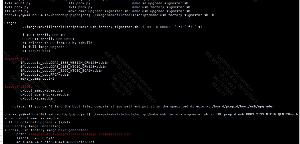
You can choose to upgrade all or some partitions:
After successful execution, the SstarUsbImage_xxxx(date).bin blank flash upgrade package is generated in the project\image\output\images directory
-
There are three ways to enable the upgrade function in U-Boot, with the second method being the recommended one. The other two methods are as follows:4.2.2 Three Methods to Enable Ufu
In uboot mode, you can directly enter the device upgrade mode by entering
ufu command.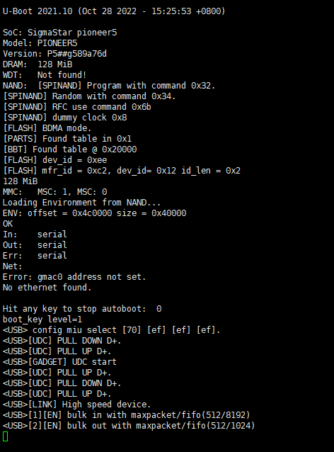
-
Directory for downloading the usbFactoryTool: SDK/Tools/UsbFactoryTool/UsbFactoryTool_xxxx tar.gz
-
Power on in blank flash mode and connect USB. You can see that there is a storage device connected to the PC.
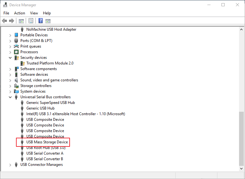
-
Connect the PC to the board to be upgraded via USB hub (The board flash must be blank). Open USB Factory Tool.exe, and the following is displayed:
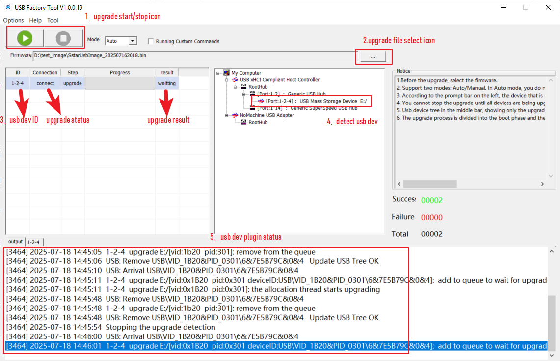
The functions of each ICON in the figure are as follows:
1→Upgrade start and stop buttons. Please note that the stop button can only be pressed after all connected devices have been successfully upgraded.
2→Upgrade package selection button: Used to select the upgrade package file of the USB blank;
3→USB device upgrade status and result display bar. It should be noted that there are currently two states for blank flash upgrade: preparation and upgrade. You must wait until the upgrade status is successful before unplugging the USB device and plugging in another USB device for upgrade;
4→Show the currently identified USB devices
5→USB device inserted and displayed status log
-
Select the USB upgrade package file, wait for all plugged in devices to be recognized, and then click the start button to upgrade. The interface after the upgrade is completed is as follows:

The functions of each ICON in the figure are as follows:
1→Show the results of each device upgrade;
2→Show the log of each device upgrade;
3→Show the number of all connected devices and the status of the upgrade;
4→Show the detected USB devices. Please note that the detected USB devices will be removed after the upgrade is successful.
According to the upgrade status of each device displayed in 1→, perform the following operations:
-
Upgrade successful: Unplug the corresponding device and plug in another blank flash to continue the upgrade;
-
Upgrade failed: You can try to plug and unplug the device and upgrade again to see if it works.
-
2.1.2 USB Device Upgrade in Blank Mode
Environment required:
There is a complete PCB with a USB interface, but the nandflash, norflash, and emmc are empty. The blank flash upgrade only supports port0
Implementation principle:
When IC is powered on, ROM code is executed first, and then IPL is executed in flash/emmc/sdmmc according to external hardware configuration. If IPL data is not found, the system automatically enters ufu upgrade mode. u-boot.bin is preloaded through PC tool (packaged into SstarUsbImage_xxxx(date).bin blank flash upgrade package through make_usb_factory_sigmastar.sh).
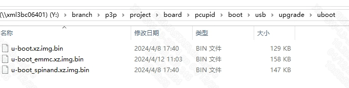
This mode requires: pre-loaded u-boot.bin (release directory: project/board/pcupid/usb/upgrade/*, released by default). It has ufu upgrade capability.Make a preload with ufu upgrade capability bin
Steps:
The upgrade procedures for blank chips and non-blank chips are essentially the same. However, since the system automatically enters UFU (U-Boot Firmware Update) upgrade mode in blank-chip mode, you can directly skip Step 3 (enabling U-Boot upgrade function) in the non-blank chip upgrade process. For detailed steps, please refer to:2.1.1 Enter ufu upgrade under uboot (Non-blank flash upgrade) 1 2 4 5 6 7
2.2. Flash_Tool Burning
This method is suitable for blank flash burning or when the board cannot enter the Uboot console.
If it is not a blank flash or can be boot normally, if you want to use Flash Tool to burn, you need to disable Debug Uart first according to the following method
-
Enter
debugdirectly in the uboot console, then close the serial terminal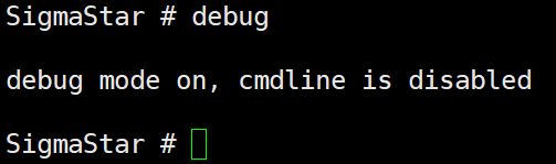
-
kernel, enter
11111and then close the serial terminal
2.2.1 SPI NAND Flash and SPI NOR FLASH burning
- Power on and make sure that the serial port log cannot be executed to the uboot console (if it can be boot normally, you need to enter the debug command in the uboot console to stop the serial port debugging function)
- Disable the serial port debugging terminal
-
Booting to Uboot requires the necessary partitions and partition start addresses
The Nand/Nor partition addresses are as follows:
Nand Flash:
Binary file offset Binary location directory cis.bin 0x00000 project\image\output\images\cis.bin cis.bin 0x20000 project\image\output\images\cis.bin boot.bin 0x140000 project\image\output\images\boot.bin PS: Nand provides a script burning method, one-click burning the entire image
Binary file Offset Binary location directory OnebinnandBurnImgConfig.cfg 0x00000 project\image\output\images\OnebinnandBurnImgConfig.cfg Nor Flash:
Binary file offset Binary location directory boot.bin 0x000000 project\image\output\images\boot.bin -
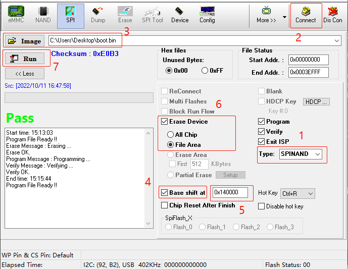
Open Flash_Tool (Version 5.0.42 and above is required), and burn the partitions in sequence according to the above partitions and partition start addresses as follows:
- Select Flash Type (Nand Flash/Nor Flash)
- Click Connect to establish the connection (be sure to close the serial port tool when connecting, otherwise there will be a problem of competing for serial port resources)
- Select the img corresponding to the partition to be burned. The screenshot takes Nand Flash burning boot.bin as an example
- Check
Base shift atand select to start from base address 0 - Fill in the starting address of the corresponding img partition (Nand's boot.bin corresponds to 0x140000)
- Make sure that the Erase Device is selected as File Area
- Click Run and wait for the run to end until the Pass status is prompted.
-
Fill in the partition and partition address corresponding to the Flash Type in step 3, and repeat the burning according to step 4. After burning, restart and you can start normally to the Uboot console, and then you can use the Tftp network port to burn.
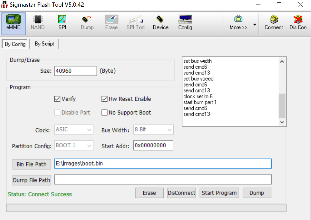
2.2.2 eMMC Burning
-
Power on and make sure that the serial port log cannot be executed to the uboot console (if it can be boot normally, you need to enter the debug command in the uboot console to stop the serial port debugging function)
-
Disable the serial port debugging terminal
-
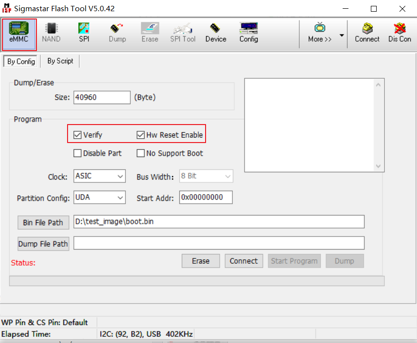
Enable Flash_tool and select emmc→config interface according to the figure below
-
Select the Bin file to be upgraded, click Connect, and the status will show Connect Success.
-
After clicking Erase, click Start Program again, and the upgrade is successful with “Status: Success. Please reset power”
-
After burning, restart and you can boot into the uboot console normally, then you can use Tftp to burn
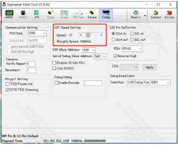
PS: If the BGA14 ISPTOOL cannot connect to the board, you can try to reduce the default 400K I2C of the ISPTOOL debug board to 108K as shown below, because the waveform will be disturbed when it is connected at high speed.
Introduction to some button functions on the By Config interface
Split Bin
-
Enable: Whether to cut bins when burning bins, used in scenarios with relatively small IMI
-
Bin Size: The size of each Bin file when splitting the Bin
It is recommended to use the default configuration for these two items and do not modify them at will.
Program
-
Bus Width: The bus width at startup is automatically obtained and does not need to be set manually.
-
Partition Config: Configure the eMMC boot partition and burning partition.
-
Disable Part: Disable booting from eMMC.
-
Hw Reset Enable: Whether to enable eMMc hardware reset. eMMc boot uses hard reset. If the hard reset of eMMc is off, it cannot boot. You need to turn on this switch.
-
Erase: Whether to erase the corresponding partition.
-
verify : Whether to verify while burning Bin.
2.3. Tftp Burning (LAN Port Burning)
This burning method is only for the case where you can enter the Uboot console (blank flash or unable to boot to the console does not support this burning method).
-
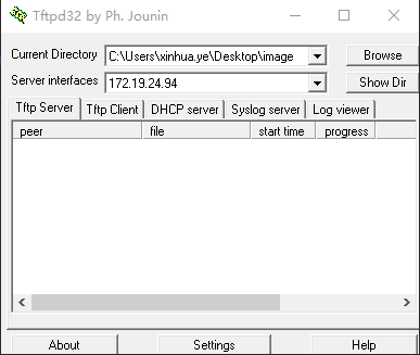
Enable the tftpd32 tool and select the images directory to be burned (project\image\output\images)
-
Press and hold Enter to enter the Uboot console and set the IP as follows:
setenv ipaddr 192.168.1.8; //Set the board IP address, which should be able to ping with the PC.
setenv serverip 192.168.1.9; //Set the IP address of the PC
setenv -f ethact sstar_emac; //Set to use Emac, this platform uses Emac
setenv -f ethaddr 0:11:22:33:44:55; //Set mac address
setenv -f netmask 255.255.255.0; //Set the netmask
setenv -f gatewayip 192.168.1.1; //Set gateway
estart //Initialize the network. You need to enter this command before using the network under uboot.
saveenv;
-
Enter estar (the difference from full burning is that this method can use the script in
estar auto_update.txtto burn any separate partition)Note:
- To ensure smooth burning, please make sure that the PC and development board are in the same network segment.
- You can use static method to assign fixed IP to prevent IP address from jumping during burning.
- You can also use an independent network card to connect the PC directly to the development board, fix the intranet IP address of the network card, and set the development board as above.
2.4. OTA Upgrade
OTA (Over-the-Air) is a technology for data transmission and updates via wireless means, typically used for software, firmware, or configuration updates on electronic devices such as smartphones, cars, and IoT devices. OTA allows for remote transmission between the device and the server, enabling users to update without connecting the device to a computer or performing wired operations. For more details, please refer to the OTA Upgrade Usage Reference.
2.5. USB&SD Upgrade
For more details, please see USB&SD Upgrade
3. Master film production
Refer to SDK/Tools/sigmastarbin/SstarMakebin_Manual.pdf
4. FAQ
4.1 Make a preloaded bin with ufu upgrade capability 
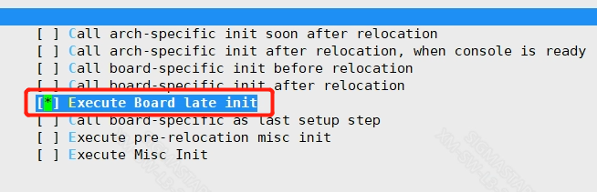
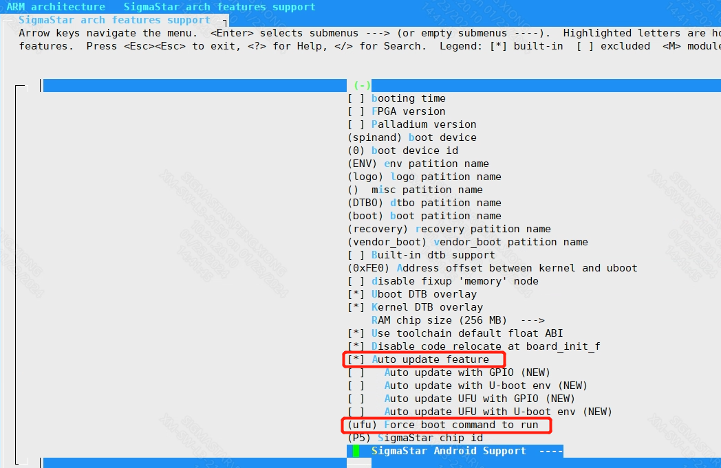
Make a preloaded bin with ufu upgrade capability, and the uboot menuconfig is configured as follows:
Init options
    -->Start-up hooks rch features support
        -->[*] Execute Board late init
ARM architecture
    -->SigmaStar arch features support
        -->[*] Auto update feature
        -->(ufu) Force boot command to run
After the compilation is complete, replace the generated preloaded u-boot.bin according to the flash type, and change the bin file name to be consistent with the file name to be replaced in the project/board/pcupid/usb/upgrade/ directory. The modification principle is as follows:
4.2 Uboot supports upgrade configuration
4.2.1 Uboot supports upgrade configuration
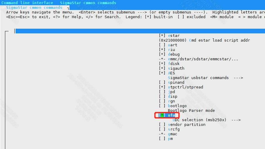
    location:
    Command line interface
        -->SigmaStar cmmon commands
            -->[*] ufu

Support ufu upgrade, but do not enable automatic operation.
4.2.2 Three Methods to Enable Ufu 
Method 1:
Auto update UFU with U-boot env(ota_upgrade_status) option in menuconfig.
Set the following parameters in boot mode, and the device will enter device upgrade mode after reboot.
    setenv ota_upgrade_status 1

    saveenv
Method 2:
In uboot mode, you can directly enter the device upgrade mode by entering ufu command.
Method 3: (Enter UFU Mode through gpio button detection)
Auto update UFU with GPIO option in menuconfig .
Long press the specified preset button and power on the device. After booting, uboot detects the button trigger and automatically enters the device ufu upgrade mode.
If you need to specify the corresponding GPIO, you need to configure it according to the following method, compile and re-burn uboot.
To configure the specified button to specify the state: modify FORCE_UPGRADE_GPIO (specified IO), FORCE_UPGRADE_ACTIVE_HIGH (specified state) under boot/common/autoboot.c, as shown in the following figure:
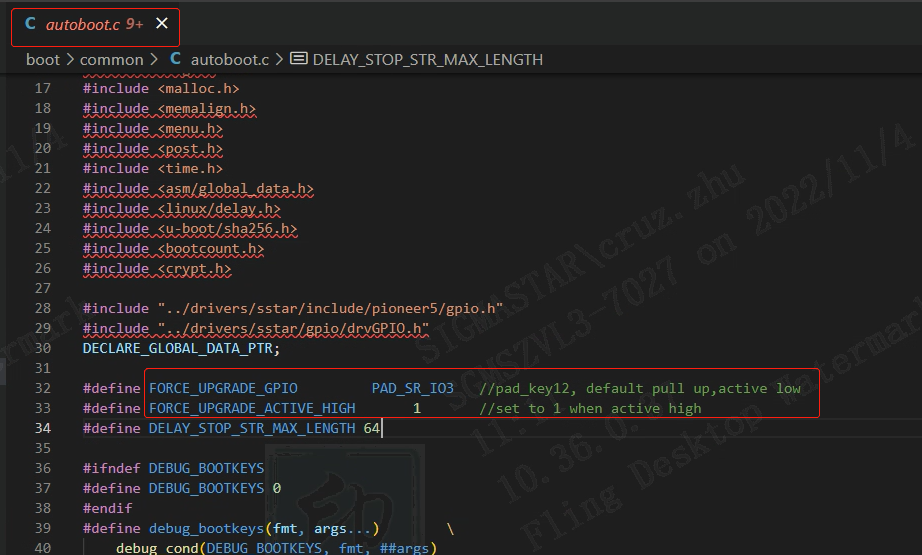
Implementation principle: When uboot starts, by detecting the specified state of the specified IO, choose whether to enter ufu mode (device upgrade mode), the relevant code is implemented in autoboot.c, and you can study it by yourself if you are interested.
4.2.3 Usage Instructions for make_usb_factory_sigmastar.sh
Under the project, you need to make image first, build it, and then use make_usb_factory_sigmastar.sh to generate it. The usage is as follows:
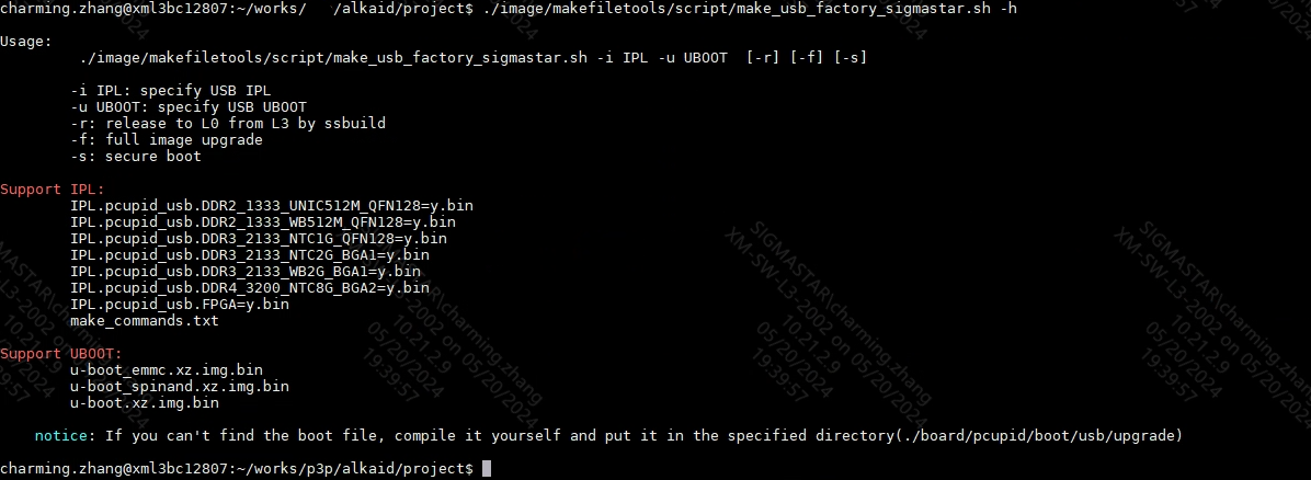
Note: Depending on the actual scenario of the customer, different IPL/UBOOT needs to be specified. If IPL and UBOOT are not specified, the IPL/UBOOT configured in config will be used, as shown in the following figure:

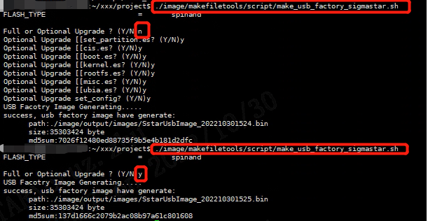
From usage, if -f is used, es in auto_update.txt need to be upgraded. If -f is not used, it will prompt "Full or Optional Upgrade". In this case, you need to enter it manually.
-
When prompted for "Full or Optional Upgrade", enter Y or press Enter to upgrade all files in auto_update.txt.
-
When prompted for "Full or Optional Upgrade", enter N, and then you need to select the target es to upgrade in turn. These es are obtained by parsing auto_update.txt.
Some operations are shown below:

4.2.4 Upgrade via USB tools
USB tools are introduced as follows
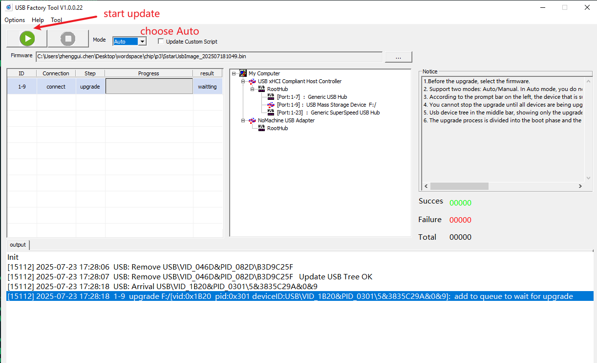
The tool supports two modes: Auto upgrade and manual upgrade.
auto mode
Generally speaking, auto is used in production lines, which can automatically detect device insertion and automatically upgrade. The steps are as follows
-
Select firmware
-
Click the Start Upgrade button, then you can insert the device and the upgrade will start automatically. The upgrade process is divided into two stages, the preparation stage and the upgrade stage. Only devices that succeed in the upgrade stage are considered to have been successfully upgraded.
Manual mode
Manual mode is generally used for development. You need to select a device to upgrade, as shown in the figure below. You need to manually select the upgrade device (USB mass storage device), and then click the upgrade button, as shown in the figure below.
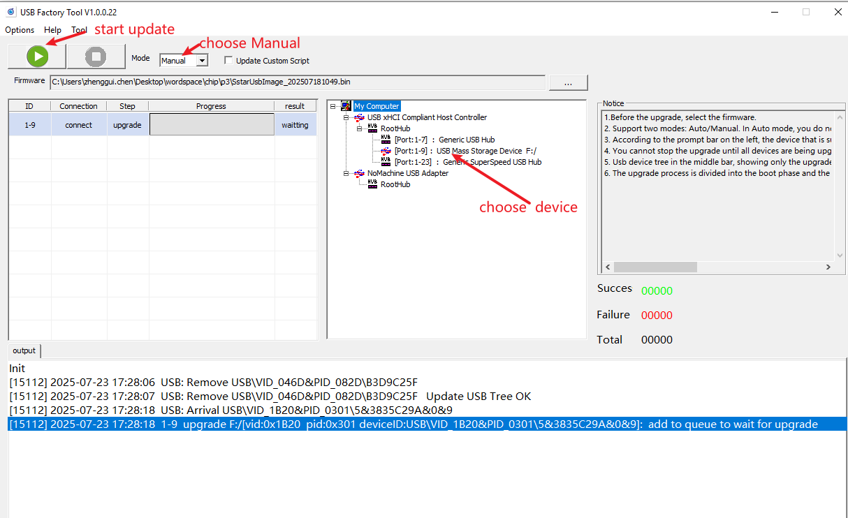
Here are the steps:
-
Select the firmware packaged with the script
-
Click the connected device in the device tree
-
Click the Start Upgrade button