MI VENC API
REVISION HISTORY
| Revision No. | Description |
Date |
|---|---|---|
| 3.0 | 12/04/2020 | |
| 3.1 | 01/19/2021 | |
| 3.2 | 01/26/2021 | |
| 08/25/2021 | ||
| 3.3 | 11/17/2021 | |
| 3.4 | 02/18/2022 | |
| 03/04/2022 | ||
| 3.5 | 03/24/2022 | |
| 03/25/2022 | ||
| 04/22/2022 | ||
| 3.6 | 05/31/2022 | |
| 06/27/2022 | ||
| 07/21/2022 | ||
| 09/30/2022 | ||
| 10/14/2022 | ||
| 3.7 | 10/27/2022 | |
| 12/01/2022 | ||
| 01/10/2023 | ||
| 3.8 | 03/13/2023 | |
| 04/04/2023 | ||
| 04/12/2023 | ||
| 05/05/2023 | ||
| 05/06/2023 | ||
| 06/05/2023 | ||
| 06/12/2023 | ||
| 06/13/2023 | ||
| 3.9 | 06/21/2023 | |
| 3.10 | 07/03/2023 | |
| 07/25/2023 | ||
| 3.11 | 08/07/2023 | |
| 11/17/2023 | ||
| 3.12 | 12/08/2023 | |
| 3.13 | 05/11/2024 | |
| 3.14 | 08/05/2024 | |
| 3.15 | 05/19/2025 | |
| 3.16 | 07/21/2025 | |
| 3.17 | 08/08/2025 | |
| 3.18 | 11/28/2025 |
1. OVERVIEW
1.1. Module Description
The video coding module compresses YUV data into a code stream conforming to the corresponding protocol according to the video compression protocol standard. The coding type supports H264/H265 and JPE. The video encoding module mainly provides the creation and destruction of video encoding channels, starting and stopping receiving images, setting and acquiring encoding channel attributes, acquiring and releasing code streams and other functions.
This module supports multi-channel real-time coding, each channel is independent, and different coding protocols and attribute parameters can be set.
Keyword Description
-
QP
Quantization Parameter. QP value corresponds to the sequence number of quantization step. The smaller the value is, the smaller the quantization step is. The higher the accuracy of quantization, the better the image quality and the larger the encoded size.
-
GOP
Group Of Pictures. The interval between two I frames. The video image sequence consists of one or more GOPs which are independent.
-
MB
Coding macroblock, the basic unit of H.264 encoding.
-
CU
Coding Unit, the basic unit of H.265 encoding.
-
SPS
Sequence Parameter Set. It contains the public information of all images in a GOP.
-
PPS
Picture Parameter Set. It contains the parameters used to encode an image.
-
SEI
Supplemental Enhancement Information.
-
ECS
Entropy-Coded Segment. Compressed image strip after entropy encoding of JPEG.
-
MCU
Minimum Coding Unit, the basic unit of JPEG encoding.
1.2. Encoding Process

The encoding process includes receiving the input image, coding the input image, and outputting the encoded stream. H.264/H.265/AV1 input image YUV format only supports NV12, while JPEG input image YUV format supports NV12 and YUYV422.
The input sources of this module include the following two types, as shown in the figure below:
-
The user's app directly sends image data to the encoding module
-
The pre-bound module sends image data to the encoding module

1.3. Function Introduction
The MI_VENC module supports the following functions:
-
Support encoding and outputting H264/H265/JPEG code stream
-
Support output YUV (not support amplification)
-
Support multiple coding rate control modes
-
Support coding overlay RGN module control
-
Support coding large frame control
-
Support coded reference frame management
-
Support H264/H265 encoding and SCL E_MI_SYS_BIND_TYPE_HW_RING binding low latency low memory mode, JPEG encoding E_MI_SYS_BIND_TYPE_REALTIME binding low latency low memory mode
-
Support E_MI_SYS_BIND_TYPE_HW_RING binding low memory mode between H264/H265 encoding channels
-
Support ROI settings and user-defined block level QP adjustment mapping
1.4. Application scenarios
Applications can be developed in the Linux/DualOS/Pure Rtos environment based on the API interface provided by MI_VENC. DualOS supports the configurable design of preload. It can cache the encoded data before the Linux system starts to achieve the purpose of fast streaming. In the RTOS phase, it will complete the pipeline concatenation, and then immediately fetch the stream transmission when the Linux environment is ready.
1.5. Chip Difference
For the current document, please refer to the description of Iford.
1.5.1. Encoding Protocol
The coding protocols supported by different chips are as follows:
Chip |
Encoding Protocol |
|||
|---|---|---|---|---|
JPEG |
H264 |
H265 |
AV1 |
|
| Maruko | Y | Y | Y | N |
| Opera | Y | Y | Y | N |
| Souffle | Y | Y | Y | Y |
| Iford | Y | Y | Y | N |
1.5.2. Encoding Process
-
Maruko Encoding Process


The device ID used to encode H.264/H.265 is MI_VENC_DEV_ID_H264_H265_0.
The device ID used to encode JPEG is MI_VENC_DEV_ID_JPEG_0.
-
Opera Encoding Process
The device ID used to encode H.264/H.265 is MI_VENC_DEV_ID_H264_H265_0.
The device ID used to encode JPEG is MI_VENC_DEV_ID_JPEG_0.
-
Souffle Encoding Process

The device ID used to encode H.264/H.265/AV1 is MI_VENC_DEV_ID_H264_H265_0.
The device ID used to encode JPEG is MI_VENC_DEV_ID_JPEG_0.
-
Iford Encoding Process
The device ID used to encode H.264/H.265 is MI_VENC_DEV_ID_H264_H265_0.
The device ID used to encode JPEG is MI_VENC_DEV_ID_JPEG_0.
1.6. Operational Principle
1.6.1. Encoding Channel
As a basic control unit, coding channels are completely independent of one another. Encoder (HW) completes the function of converting the original image into a code stream, which is completed by the control of Rate Controller and the Encoder (SW) in cooperation. The Rate Controller and Encoder (SW) of each channel stores all the resources set and managed by all users of the current encoding channel, such as rate control, buffer demand and allocation, etc. The rate control ensures the balance between the output rate and the image quality, while the encoder focuses on the realization of the syntax elements of each codec. Software and hardware control, at the same time, a codec hardware time-sharing multiplexing. Taking two coding channels for example, the basic block diagram of coding channel is as follows:

1.6.2. Rate Control
From the perspective of Informatics, the image compression ratio is inversely proportional to the quality: the higher the compression ratio, the lower the quality; the lower the compression ratio, the higher the quality.
Taking H.264 as an example, the lower the general image QP, the higher the image quality and the higher the bit rate; the higher the image QP, the lower the image quality and the lower the bit rate. The rate control algorithms supported by different coding protocols are as follows:
Chip |
Rate Control Algorithm |
|||||
|---|---|---|---|---|---|---|
FIXQP |
CBR |
VBR |
AVBR |
UBR |
CVBR |
|
| Maruko | H.264/H.265/JPEG | H.264/H.265/JPEG | H.264/H.265 | H.264/H.265 | NONE | NONE |
| Opera | H.264/H.265/JPEG | H.264/H.265/JPEG | H.264/H.265/JPEG | H.264/H.265 | NONE | NONE |
| Souffle | H.264/H.265/AV1/JPEG | H.264/H.265/AV1/JPEG | H.264/H.265/AV1/JPEG | H.264/H.265/AV1 | H.264/H.265/AV1 | H.264/H.265/AV1 |
| Iford | H.264/H.265/JPEG | H.264/H.265/JPEG | H.264/H.265/JPEG | H.264/H.265 | H.264/H.265 | H.264/H.265 |
-
FIXQP
Fixed Quantization Parameter. At any time point, Qp of all slices of the encoded image can directly be set by the user, and the Qp of I frame and P frame can be set respectively in H.264/H.265/AV1.
The control flow chart of H.264/H.265/AV1 is as follows:

The control flow chart of JPEG is as follows:

It adopts the Qp table recommended by ITU-t81 K.1. The Qfactor set by the user is converted into a proportional factor according to a certain formula, and the multiplication of the two is the final Qp.
-
CBR
Constant Bit Rate. It can guarantee the stability of coding rate during bit rate statistics. Because of different prediction methods, the size of I frame and P frame will be significantly different after coding. The bottom statistical time is based on Gop, and the bit accumulation and compensation will be realized between GOPs.
The main steps are as follows:
-
Convert Fps/Gop/bitrate set by user to bits of each GOP.
-
Calculate the BPP (bitperpixel) according to GOP bits and resolution for the I/P frames respectively.
-
Map BPP to frame QP by rate control model.
-
Adjust MB/Cu QP using HW based on frame QP by image texture complexity and other information.
-
Update the rate control model after coding to achieve the continuous stability of the whole sequence, and accumulate the bit error for the fine-tuning of bit allocation of subsequent frames.
-
Accumulate the bit error of the GOP in its entirety after the completion of the whole GOP, for fine-tuning of the next GOP bit allocation.
The control flow chart is as follows:

-
-
VBR
Variable Bit Rate. It allows the bit rate to fluctuate within the bit rate statistics time, so as to ensure the stable quality of the coding image. Taking H.264 for example, users can set MaxQp, MinQp, MaxBitRate and ChangePos, details of which can be found in MI_VENC_ParamH264Vbr_t. MaxQp and MinQp are used to control the quality range of images. MaxBitRate is used for limiting maximum bit rate within the statistics time. ChangePos is a percentage of the maximum bit rate, which is used to control the bit rate reference start line to adjust QP, that is, when the bit rate is greater than MaxBitRate*ChangePos, the image QP will gradually adjust to MaxQp, if the image QP reaches MaxQp, the image QP will be clamped to the maximum value, the clamping effect of MaxBitRate will be lost, and the bit rate may exceed MaxBitRate. If the bit rate is less than MaxBitRate*ChangePos, the image QP will gradually adjust to MinQp, and if the image QP reaches MinQp, the bit rate will reach the maximum value and the image quality will be best under this circumstance.
The specific process is as follows:
-
Convert the Fps/Gop/MaxBitRate/ChangePos and resolution set by user into the initial quality benchmark to set starting QP of the sequence.
-
Adjust MB/CU QP using HW based on frame QP by image texture complexity and other information.
-
Update rate control model after coding.
-
Update the quality of the overall sequence.
-
Calculate the deviation coefficient according to the difference between the current expected bit and the actual encoded bit, and decide whether the quality can be improved or reduced.
-
Calculate the target quality of the current frame by the deviation coefficient and two quality coefficients
-
Map the target quality to frame QP, looping from 2.
The control flow chart is as follows:

-
-
AVBR
Adaptive Variable Bit Rate. It allows the bit rate to fluctuate within the bit rate statistics time, so as to ensure the stable quality of the coding image. The rate control will detect the static state of the current scene, adopt higher rate coding when moving, and actively reduce the rate when still. Taking H.264 for example, users can set MaxBitRate, ChangePos and MinStillPercent, details of which can be found in MI_VENC_ParamH264Avbr_t. MaxBitRate represents the maximum bit rate in the motion scene, Minstitlpercent is the percentage of the minimum bit rate relative to the adjusted threshold bit rate in the static scene, MaxBitRate * ChangePos * MinStillPercent represents the minimum bit rate in the static scene, and the target bit rate will be adjusted between the minimum bit rate and the maximum bit rate according to the different degree of motion. MaxQp and MinQp are used to control the quality range of the image. The highest priority of the rate control is QP clamp. Rate control beyond MinQp and MaxQp will fail.
-
Note
SAD functions are integrated into VENC AVBR mode starting from platform Muffin, that is, the SAD calculation function is integrated within the encoder, and the SED module is no longer needed to help calculate the SAD.
-
-
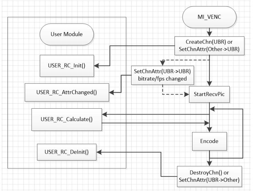
UBR
Unspecified Bit Rate, allows users to set the encoding parameters of the next frame according to the parameters output by the callback function.
-
Usage Note
Set when users want to use their own frame-level encoding control algorithm. Block-level QP supports three different modes, all identical setting, reference only the complexity adjustment and reference both complexity and user-configured frame target size.
-
Process introduction
-
API implementation
Implement 4 functions in APP, OnVencUserRcInit(), OnVencUserRcDeinit(), OnVencUserRcAttrChange(), OnVencUserRcCalc(), which four functions are called internally by VENC;
-
Create venc channel, to set UBR mode
It is similar to CBR and VBR in usage;
Selete E_MI_VENC_RC_MODE_H264UBR or E_MI_VENC_RC_MODE_H265UBR mode, refer to MI_VENC_RcMode_e;
-
Start channel
Each time VENC receives an encoded frame, it performs OnVencUserRcCalc and then encodes it according to the calculated Qp value, ensuring real-time performance;
OnVencUserRcCalc interface spending time may affect encode performance;
-
The implementation flow chart is as follows:
-
-
API instructions
Implement 4 functions in APP, OnVencUserRcInit(), OnVencUserRcDeinit(), OnVencUserRcAttrChange(), OnVencUserRcCalc(). For details, refer to the following interfaces:
-
-
CVBR
Constrained Variable Bit Rate. Simple scenes will save bit rate while ensuring image quality. In complex motion scenes, the bit rate saved by simple scenes can be used to improve the image quality as much as possible. By doing so, both bit rate and image quality can be enhanced simultaneously.
Taking H.264 as an example, users can set the bit rate parameters MaxBitRate, LongTermMaxBitRate, LongTermMinBitRate and the period parameters ShortTermStatsTime and LongTermStatsTime. For details, please refer to MI_VENC_AttrH264Cvbr_t.
MaxBitRate represents the maximum bit rate that can be achieved within the statistical time of ShortTermStatsTime. When bit rate is saved in simple scenes, MaxBitRate can be reached in complex motion scenes.
LongTermMaxBitRate represents the upper limit of the bit rate within the statistical time of LongTermStatsTime. In simple scenes, the bit rate will be adjusted lower than LongTermMaxBitRate to save bit rates for complex scenarios. By contrast, LongTermMinBitRate represents the lower limit of the bit rate within the statistical time of LongTermStatsTime. The bit rate in simple scenes will not be lower than LongTermMinBitRate.
For example:
-
When the scene is static and simple throughout the entire process, CVBR will always control the bit rate to be lower than LongTermMaxBitRate to save bit rate.
-
When the scene features complex movements throughout the entire process, CVBR will control the bit rate and maintain it at LongTermMaxBitRate since there is no bit rate savings. In this moment, the effect is the same as CBR.
-
When the scene turns from static and simple in the early stage to complex motion in the later stage, CVBR will save bit rate in the early stage. When the movement becomes complex, the bit rate can exceed LongTermMaxBitRate so as to improve image quality. The bit rate, however, will not exceed ShortTermMaxBitRate at most. If the bit rate saved in the early stage is used up, CVBR will control the bit rate and maintain it at LongTermMaxBitRate.
-
When the scene turns from complex motion in the early stage to static and simple in the later stage, CVBR will maintain the bit rate at LongTermMaxBitRate in the early stage, and then keep the bit rate lower than LongTermMaxBitRate to save bit rate in the later stage.
-
1.6.3. QPMAP
In qpmap mode, users are allowed to decide the rate control strategy by themselves, and absolute qpmap and relative qpmap are supported. Please refer to MI_VENC_AllocCustomMap.
1.6.4. Reference Frame Structure
H.264/H.265 only supports one reference frame in a single frame, but the whole stream supports multiple reference frame buffers. For example: in LTR/TSVC3 mode, each P can only refer to one, but at most two reference frames will be saved for different P frames.
The reference frame supports 6 modes: NormalP, LTR (VI Ref IDR), LTR (VI Ref VI), All P Reference IDR, TSVC-2 and TSVC-3. All reference frame structures are controlled by three parameters: u32Base, u32Enhance and bEnablePred. Please refer to MI_VENC_ParamRef_t for details. When u32Enhance is set to 0, it will be converted to NormalP reference frame structure. For other structures, please refer to the corresponding structure chart. The default structure is NormalP reference frame structure. The following details the reference diagram and parameter setting for each reference frame structure.
-
NormalP
NormalP is the most basic and common reference relationship. P frame directly refers to the previous one, and its structure diagram is shown in the following figure:

-
LTR mode
LTR (Long Term Reference) uses long-term reference frame and short-term reference frame to allow the same frame to be referred to multiple frames. This mode defines one special P as virtual I frame (VI). Compared with all IDR, using VI can reduce the bit rate while maintaining a certain error recovery capability. At present, LTR supports two modes: all VI refers to the latest IDR and VI refers to the previous VI or IDR (in the case of the first VI). The structures of the two reference modes are as follows:


Note: An extra buffer is required to enable LTR mode.
-
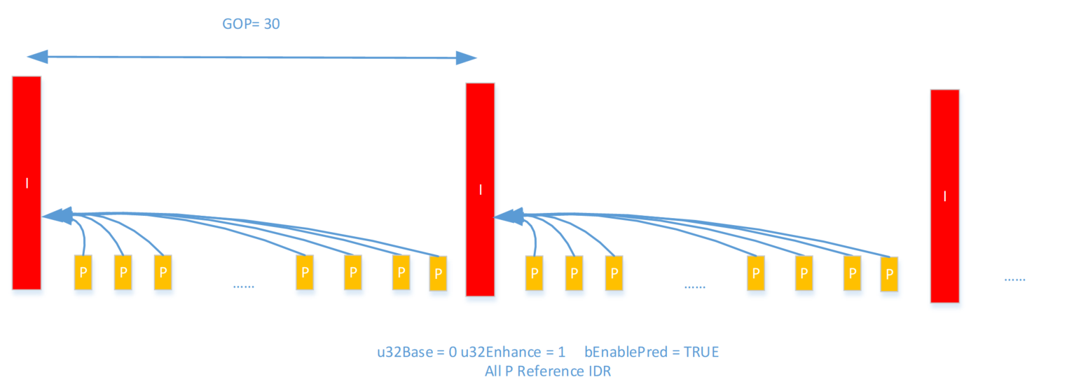
All P Reference IDR
All P Reference IDR is a special case of LTR(VI Ref IDR), it uses longterm reference type but does not need an extra buffer.
-
TSVC-2
TSVC-2 provides two-layer coding, and the frame rate can vary between ½ and full. The structure diagram is as follows:

-
TSVC-3
TSVC-3 provides three-layer coding, and the frame rate can vary between ¼, ½, ¾ and full. The structure diagram is as follows:

Note: An extra buffer is required to enable TSVC-3 mode.
1.6.5. Crop
Crop, that is, cutting out a part of the image for encoding. User can set the left/top starting point of clipping, and the width and height. Please refer to relevant API: MI_VENC_SetCrop. The schematic diagram is as follows:

1.6.6. ROI
Region Of Interest coding. Users can configure ROI region to limit the image QP of this region, so as to realize the difference between the QP of this region and the QP of other image regions. The system supports H.264/H.265/AV1 codes to set ROIs. Depending on the platform, a maximum of 8 or 16 ROI regions can be selected by users for simultaneous use.
If the platform supports a maximum of 16 ROI regions, the 16 ROI regions can be superimposed on one another, and the priority of the superimposed regions is increased in turn according to the index from 0 to 15, that is, the final Qp of the superimposed regions is determined solely by the region with the highest priority. The ROI region can be configured with absolute QP and relative QP:
Absolute QP: the QP in ROI region is the QP value set by the user
Relative QP: the QP in ROI region is the sum of the QP generated by rate control and the QP offset value set by the user
In the following example, the encoded image adopts the fixqp mode, setting the image QP to 30, that is, the QP value of all macroblocks of the image is 30. ROI region 0 is set to absolute QP mode, QP value is 20, index is 0; ROI region 1 is set to relative QP mode, QP is -15, index is 1. Because the index of ROI region 0 is smaller than the index of ROI region 1, the QP of ROI region 1 with high priority is set in the overlapped image region. The QP value of region 1 is 30-15 = 15, and the QP value of region 0 except the overlapped image region is 20.

1.6.7. Low Frame Rate Encode in Non ROI Region
Low frame rate encode in non ROI region, that is, the ROI region is normally encoded after the ROI is turned on, while the non ROI region can reduce the frame rate by setting the proportional relationship between the source and the target. According to the scale relationship, the non ROI region of some frames in a GOP will directly use the data of the corresponding area of the previous frame. The user can set the relative frame rate of non ROI region according to the actual situation, and only when the ROI is turned on can it take effect. Please refer to MI_VENC_SetRoiBgFrameRate, wherein s32srcFrmRate and s32dstFrmRate only represent a proportional relationship, irrelevant to the actual frame rate.
Note: The Souffle platform does not support low frame rate encoding for non-ROI regions.
1.6.8. Bind Type
Generally speaking, the bind type between front level and VENC is E_MI_SYS_BIND_TYPE_FRAME_BASE, that is, the front level completes a frame buffer completely, and then outputs it to the Venc. In this mode, at least three frame buffers need to be allocated. If the front level is SCL, there are two bind types which can save memory: E_MI_SYS_BIND_TYPE_HW_RING and E_MI_SYS_BIND_TYPE_REALTIME.
E_MI_SYS_BIND_TYPE_HW_RING means that SCL and VENC can read and write on the same one frame buffer at same time. This can effectively save buffers between modules, but different chips support different minimum buffers.
E_MI_SYS_BIND_TYPE_REALTIME has two modes: one is IMI mode and the other is EMI mode. If IMI mode is used, no additional Dram buffer is allocated between SCL and VENC. SCL and VENC read and write on the internal Sram buffer. If EMI mode is used, a Dram buffer is allocated between SCL and VENC, and SCL and VENC read and write on this Dram buffer. Since IMI mode is not supported on Souffle/Iford platform, EMI mode is used by default when binding E_MI_SYS_BIND_TYPE_REALTIME, which consumes a Dram buffer. Other platforms use IMI mode by default, so this mode cannot be modified for now.
For the contents in the subsequent tables in the current section, please refer to the Iford part.
Different chip and encode protocols support different bind type as illustrated follows:
Chip |
Codec |
Bind Type |
||
|---|---|---|---|---|
| FRAME_BASE | HW_RING | REALTIME | ||
| Maruko | H.264/H.265 | Y | Y | N |
| JPEG | Y | N | Y | |
| Opera | H.264/H.265 | Y | Y | N |
| JPEG | Y | N | Y | |
| Souffle | H.264/H.265/AV1 | Y | Y | N |
| JPEG | Y | N | Y | |
| Iford | H.264/H.265 | Y | Y | N |
| JPEG | Y | N | Y | |
When E_MI_SYS_BIND_TYPE_REALTIME is bound and in IMI mode, the maximum width supported by different Chip and input image YUV format is as follows:
Chip |
Input Yuv Format |
|
|---|---|---|
| NV12 | YUYV422 | |
| Maruko | Not Supported | 3840 |
| Opera | 1920 | 1920 |
| Souffle | Not Supported | Not Supported |
| Iford | Not Support | Not Support |
When E_MI_SYS_BIND_TYPE_REALTIME is bound in EMI mode, the maximum width supported by different Chip and input image YUV format is as follows:
Chip |
Input Yuv Format |
|
|---|---|---|
| NV12 | YUYV422 | |
| Souffle | 8192 | 8192 |
| Iford | 3840 | 3840 |
When the binding between SCL and VENC using E_MI_SYS_BIND_TYPE_HW_RING, the frame buffer can be configured by calling the MI_SYS_ConfigPrivateMMAPool interface provided by SYS when initializing SCL. For details on the method of use, see MI SYS API. If the sizes of the two SCL output YUVs are inconsistent, the frame buffer is applied according to the maximum output size. The minimum values of the frame buffer shared by SCL and VENC of different chips are as follows:
Chip |
Codec |
Bind Type |
||
|---|---|---|---|---|
| HW_RING | REALTIME | |||
| Maruko | H.264/H.265 | 1/4 Buffer when IFC is enabled, 1/2 Buffer when IFC is not enabled | N | |
| JPEG | N | Configuration not supported, default set to 16 | ||
| Opera | H.264/H.265 | 1/4 Buffer when IFC is enabled, 1/2 Buffer when IFC is not enabled | N | |
| JPEG | N | Configuration not supported, default set to 16 | ||
| Souffle | H.264/H.265/AV1 | 1 Buffer | N | |
| JPEG | N | Configuration not supported, default set to 1 | ||
| Iford | H.264/H.265 | 1 Buffer | N | |
| JPEG | N | Configuration not supported, default set to 1 | ||
Note:
-
VENC supports outputting YUV simultaneously and the subsequent level can cascade VENC sub-channels. The bind type between VENC channels needs to set E_MI_SYS_BIND_TYPE_HW_RING. Each sub channel of VENC shares a frame buffer for YUV data stream transmission, which only supports the reading and writing of the whole sheet. Since the VENC cascade only supports reduction, and the output size of the subsequent channel must be less than or equal to the output of the previous channel, the frame buffer can be configured once by calling the MI_SYS_ConfigPrivateMMAPool interface by VENC main channel according to the maximum output size in the subchannel. The working model is as follows:

When VENC is cascaded, the resolution of the output ES matches that of the input YUV. The resolution of the output YUV must be less than or equal to the resolution of the input YUV. For example, in the diagram below, the resolution of the output ES will be consistent with that of the VENC INPUT YUV PORT.
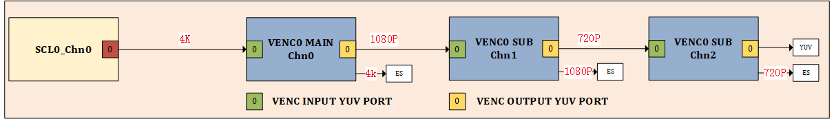
-
The last level of VENC output YUV supports user Get/Put function. At this time, the user needs to configure an independent YUV output Buffer.
-
For the E_MI_SYS_BIND_TYPE_REALTIME binding, Maruko does not support NV12 image format, but only YUYV422 image format.
1.6.9. Output Buffer Configuration of Coded Bitstream
Different chips support different configurations due to different SW architectures. The default configurations are as follows:
| Chip | H.264 | H.265 | JPEG |
|---|---|---|---|
| Maruko | Ring pool:WidthxHeight/2 | Ring pool:WidthxHeight/2 | Ring pool:WidthxHeight/2 |
| Opera | Ring pool:WidthxHeight/2 | Ring pool:WidthxHeight/2 | Ring pool:WidthxHeight/2 |
| Souffle | Ring pool:WidthxHeight/2 | Ring pool:WidthxHeight/2 | Ring pool:WidthxHeight/2 |
| Iford | Ring pool:WidthxHeight/2 | Ring pool:WidthxHeight/2 | Ring pool:WidthxHeight/2 |
The above is the default output buffer configuration of each chip. User can specify the output buffer configuration by MI_VENC_CreateChn. Taking H.264 as an example, user can specify the output buffer configuration by setting stVeAttr.stAttrH264e.u32BufSize. If the value is 0, the default configuration is used. In the ring pool mode, on the other hand, each channel will separately allocate an output ring pool, and each coding will obtain the maximum free buffer from the pool, and then record the size of the actual coding used, and recycle the output ring pool, which will effectively improve the utilization of the buffer and reduce memory fragmentation.
*Note: 1.The actual number of frames that the output pool can store is related to the Buffer configuration and u32MaxStrmCnt (configured through MI_VENC_SetMaxStreamCnt). When the number of buffered bitstreams has reached u32MaxStrmCnt or the number of buffered bitstreams has reached the size of the output pool, frame drop or a "buffer full" log may occur. The bitstreams size of each encoded frame is highly correlated with the content of the scene, the settings of the bitrate control parameters, etc. Different configurations may result in a difference of 10 times or even 100 times.
2.After turning on preload under DualOs, an additional output pool will be requested according to the number of frames to be preload. This output pool will be automatically released after all the preload frames have been retrieved.
3.Under the Maruko/Opera/Souffie Chip, the JPE internally requests two output pools to support full - frame output in real - time mode. Otherwise, it can only reach half of the output frame rate of the front - end MI SCL. If the JPE only operates in frame mode or has low frame - rate requirements in real - time mode, adjust the parameter max_jpe_task = 1 to force the opening of one output pool and save memory.*
For example, you can modify modparam.json file(it is usually under /config path in the board), and add the following fields:
"E_MI_MODULE_ID_VENC" :
{
    "max_jpe_task": 1
}
1.6.10. Scenarios Supported by Multi-Processes
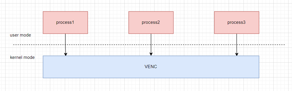
Supported scenarios:
-
Same-device, different-channel multi-process coding
For example:
Process1 creates Device0, channel0 encoding. Process2 creates Device0, channel1 encoding. Process3 creates Device0, channel2 encoding.
-
Different-device multi-process coding
For example:
Process1 creates Device0, channel0 encoding. Process2 creates Device8, channel0 encoding. Process3 creates Device9, channel0 encoding.
-
Getting and setting parameters in a separate process other than the process used for the multi-process coding
For example:
Process1 creates Device0, channel0 encoding and Device1, channel0 encoding. Process2 creates Device0, channel1 encoding and Device1, channel1 encoding. You can get and set parameters of device0's channel0 and channel1 code channels and Device1's channel0 and channel1 code channels in process3. For example process3 calls the MI_VENC_SetChnAttr function to set the encoding channel properties of Device0, channel0.
Note: Resources created in process1, such as Device0 and channel0, need to be destroyed in process1.
Unsupported scenarios:
-
Streaming and fetching of coded channels created by process 1 in process 2
For example:
Process1 creates Device0, channel0, but does not stream. Process2 sends and receives streams from Device0 and channel0.
-
Binding of the front-level module channels created by process 1 to the VENC channels created by process 2. Streams need to ensure that the front-level and rear-level channels are created in the same process.
For example:
Process1 creates Device1, channel0 channel of SCL. Process2 creats Device0, channel0 channel for VENC. Binding Device1, channel0, port0 of SCL to Device0, channel0, port0 of VENC in Process1 or Process2 is not supported. If you want to stream, you need to ensure that both the front-level and the rear-level channels to be bound are created in the same process.
1.6.11. Frame Rate Control
-
When the venc module is bound with the front-level module (See section 1.4.16 for BindType), the rear-level of the venc main channel is not connected to a venc sub stream and the venc main channel does not need to output YUV:
The user can control the output frame rate of a venc channel by calling MI_SYS_BindChnPort2 to set the input frame rate parameter (u32SrcFrmrate) of the front-level module (scl) and the output frame rate parameter (u32DstFrmrate) of the rear-level module. In this case, the output frame rate can only be less than or equal to the input frame rate.
In this case, if the output frame rate of the venc channel is changed halfway, user needs to call MI_SYS_UnBindChnPort interface to unbind the modules and call MI_SYS_BindChnPort2 interface to reset the frame rate parameter.
-
When the venc module is bound with the front-level module, the venc main channel is connected to a sub stream or the venc main channel need to output YUV:
The way that the user controls the output frame rate of a venc channel will change. MI_SYS_BindChnPort2 interface is called to set the input frame rate parameter (u32SrcFrmrate) of the front-level module (scl or venc) to be equal to the output frame rate parameter(u32DstFrmrate) of the rear-level module, and MI_VENC_CreateChn is called to set the output frame rate parameter of the current channel. The final actual output frame rate is controlled by the frame rate parameter which is set in MI_VENC_CreateChn. Take H264 encoding FixQp as an example:
MI_VENC_ChnAttr_t stChnAttr;
stChnAttr.stRcAttr.stAttrH264FixQp.u32SrcFrmRateNum = 30;
stChnAttr.stRcAttr.stAttrH264FixQp.u32SrcFrmRateDen = 1;
MI_VENC_CreateChn(VeDev, VeChn, &stChnAttr);
In this way, the output frame rate of the rear-level channel can be greater than the output frame rate of the front-level channel. However, if the input frame rate of the main channel (from scl module) is less than the output frame rate, the frame rate control will not be performed, and the output frame rate will be equal to the input frame rate of the main channel, as shown in the figure below:

In this way, if the output frame rate of the venc channel needs to be changed halfway, the user needs to call the MI_VENC_SetChnAttr interface to reset the output frame rate parameter. Take H264 encoding FixQp as an example:
MI_VENC_ChnAttr_t stChnAttr;
MI_VENC_GetChnAttr(VeDev, VeChn, &stChnAttr);
stChnAttr.stRcAttr.stAttrH264FixQp.u32SrcFrmRateNum = 15;
stChnAttr.stRcAttr.stAttrH264FixQp.u32SrcFrmRateDen = 1;
MI_VENC_SetChnAttr(VeDev, VeChn, &stChnAttr);
1.7. Development Process
1.7.1. Compile Configuration
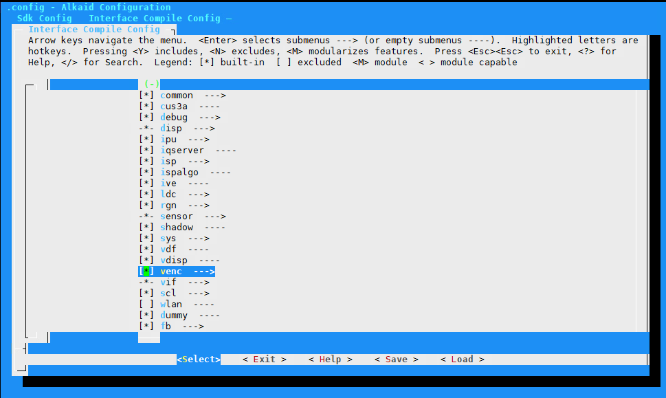
-
Enter the root directory of the alkaid project, make menuconfig
-
Enter to enter Sdk Config sub option
-
Enter to enter the interface compile config sub option
-
Select the venc sub module with the space bar, save and recompile the project
After compilation, mi_venc.ko will be generated under sdk/interface/src/venc, and mi_venc.h and mi_venc_datatype.h will be released to the project/release directory. In the pure linux environment, it will be packaged into images by default.
1.7.2. Configure MI_VENC Module Loading Parameters
The modparam.json file is in the/config directory, and will be parsed and loaded in the VENC initialization phase.
Refer to Chapter 6 for common fields and meanings of modparam.json.
1.7.3. API Process

The MI_VENC universal stream mainly includes the following steps:
-
MI_SYS initialization
-
Create MI_VENC device
-
Create MI_VENC channel
-
If the data source is a previous module, call MI_SYS API to bind other modules
-
Open the encoding channel to receive the input image
-
Get fd corresponding to the encoding channel
-
If the data source is user injection, call MI_SYS API to fill in the data (choose one from this step and step 4)
-
Listen to the venc fd by select
-
Query coding channel status
-
Get the encoded stream
-
Release the stream buffer
-
Repeat steps 7-11 for cycle coding
-
Stop encoding channel receiving input image
-
If the data source is the previous module, call MI_SYS API to unbind other modules (this step is performed in pairs with step 4)
-
Destroy MI_VENC channel
-
Destroy MI_VENC device
-
MI_SYS de-initialization
1.8. Example
This example introduces the basic process of single channel H264 coding injection into NV12 YUV, and the rate control is CBR. Due to the lack of space, the return value has not been checked, and it needs to be processed in practical applications. For the specific meaning of parameter settings, please refer to Chapter 2 Introduction to API and Chapter 3 Introduction to Data Types.
#include <stdio.h>
#include <stdlib.h>
#include <string.h>
#include "mi_sys.h"
#include "mi_sys_datatype.h"
#include "mi_venc.h"
#include "mi_venc_datatype.h"

MI_S32 VencEncodeLoop(MI_VENC_DEV vencDev, MI_VENC_CHN vencChn, MI_U32 u32Fps)
{
    MI_SYS_ChnPort_t    stVencChnInputPort;
    MI_SYS_BufInfo_t    stBufInfo;
    MI_SYS_BUF_HANDLE   hHandle;
    MI_SYS_BufConf_t    stBufConf;
    MI_VENC_ChnStat_t   stStat;
    MI_VENC_Stream_t    stStream;
    MI_VENC_Pack_t      *pstPack = NULL;
    MI_U32              u32PackCount = 0, u32Offset = 0, i = 0;
    MI_S32              s32Ret = MI_SUCCESS, vencFd = 0;
    MI_S32              s32TimeOutMs = 1000 / u32Fps * 2;
    MI_U32              u32YuvStride = 1920; //may >= encode width
    MI_U32              u32YuvHeight = 1080;
    MI_U32              u32EncNum = 500;
    MI_BOOL             bFrameEnd = FALSE;
    struct timeval      TimeoutVal;
    fd_set              readFds;
    FILE               *pInputYuvFile = NULL;
    FILE               *pOutputEsFile = NULL;
    char output_path[] = "cbr.h264";
    char input_path[]  = "1920x1080_NV12.yuv";

    memset(&stVencChnInputPort, 0, sizeof(MI_SYS_ChnPort_t));
    stVencChnInputPort.eModId    = E_MI_MODULE_ID_VENC;
    stVencChnInputPort.u32DevId  = vencDev;
    stVencChnInputPort.u32ChnId  = vencChn;
    stVencChnInputPort.u32PortId = 0;

    memset(&stBufConf, 0, sizeof(MI_SYS_BufConf_t));
    stBufConf.eBufType                  = E_MI_SYS_BUFDATA_FRAME;
    stBufConf.stFrameCfg.eFormat        = E_MI_SYS_PIXEL_FRAME_YUV_SEMIPLANAR_420;
    stBufConf.stFrameCfg.eFrameScanMode = E_MI_SYS_FRAME_SCAN_MODE_PROGRESSIVE;
    stBufConf.stFrameCfg.u16Width       = u32YuvStride;
    stBufConf.stFrameCfg.u16Height      = u32YuvHeight;
    TimeoutVal.tv_sec                   = 0;
    TimeoutVal.tv_usec                  = 100000;

    pInputYuvFile = fopen(input_path, "rb");
    pOutputEsFile = fopen(output_path, "wb");
    vencFd = MI_VENC_GetFd(vencDev, vencChn);
    FD_ZERO(&readFds);
    FD_SET(vencFd, &readFds);

    while (u32EncNum > 0)
    {
        memset(&stBufInfo, 0, sizeof(MI_SYS_BufInfo_t));
        MI_SYS_ChnInputPortGetBuf(&stVencChnInputPort, &stBufConf, &stBufInfo, &hHandle, s32TimeOutMs);

        u32Offset  = 0;
        for (i = 0; i < u32YuvHeight; i++)
        {
            /*Y data*/
            fread((char *)stBufInfo.stFrameData.pVirAddr[0] + u32Offset, 1, u32YuvStride, pInputYuvFile);
            u32Offset += stBufInfo.stFrameData.u32Stride[0];
        }
        for (i = 0; i < u32YuvHeight/2; i++)
        {
            /*UV data*/
            fread((char *)stBufInfo.stFrameData.pVirAddr[1] + u32Offset, 1, u32YuvStride, pInputYuvFile);
            u32Offset += stBufInfo.stFrameData.u32Stride[1];
        }
        MI_SYS_ChnInputPortPutBuf(hHandle, &stBufInfo, FALSE);

        s32Ret = select(vencFd + 1, &readFds, NULL, NULL, &TimeoutVal);
        if (s32Ret > 0 && FD_ISSET(vencFd, &readFds))
        {
            memset(&stStat, 0, sizeof(MI_VENC_ChnStat_t));
            s32Ret = MI_VENC_Query(vencDev, vencChn, &stStat);
            if (MI_SUCCESS != s32Ret || stStat.u32CurPacks == 0)
            {
                continue;
            }
            memset(&stStream, 0, sizeof(MI_VENC_Stream_t));
            stStream.u32PackCount = stStat.u32CurPacks;
            if(u32PackCount < stStream.u32PackCount)
            {
                if(pstPack != NULL)
                {
                    free(pstPack);
                }
                pstPack = (MI_VENC_Pack_t *)malloc(sizeof(MI_VENC_Pack_t) * stStat.u32CurPacks);
                u32PackCount = stStream.u32PackCount;
            }
            stStream.pstPack = pstPack;
            MI_VENC_GetStream(vencDev, vencChn, &stStream, s32TimeOutMs);
            if (MI_SUCCESS == s32Ret)
            {
                for (i = 0; i < (int)stStream.u32PackCount; i++)
                {
                    fwrite(stStream.pstPack[i].pu8Addr + stStream.pstPack[i].u32Offset, 1,
                            stStream.pstPack[i].u32Len - stStream.pstPack[i].u32Offset*sizeof(MI_U8), pOutputEsFile);
                    bFrameEnd = stStream.pstPack[i].bFrameEnd;
                }
                if(bFrameEnd)
                {
                    u32EncNum--;
                }
                MI_VENC_ReleaseStream(vencDev, vencChn, &stStream);
            }
        }
    }
    fclose(pInputYuvFile);
    fclose(pOutputEsFile);
    free(pstPack);

    MI_VENC_CloseFd(vencDev, vencChn);
    return NULL;
}

MI_S32 main(MI_S32 argc, char **argv)
{
    MI_VENC_DEV vencDev = 0;
    MI_VENC_CHN vencChn = 0;
    MI_VENC_InitParam_t stInitParam;
    MI_VENC_ChnAttr_t stChnAttr;

    MI_SYS_Init(0);

    memset(&stInitParam, 0, sizeof(MI_VENC_InitParam_t));
    memset(&stChnAttr, 0, sizeof(MI_VENC_ChnAttr_t));
    stInitParam.u32MaxWidth = MAX_WIDTH;
    stInitParam.u32MaxHeight = MAX_HEIGHT;
    stChnAttr.stVeAttr.eType = E_MI_VENC_MODTYPE_H264E;
    stChnAttr.stVeAttr.stAttrH264e.u32PicWidth = 1920;
    stChnAttr.stVeAttr.stAttrH264e.u32PicHeight = 1080;
    stChnAttr.stVeAttr.stAttrH264e.u32MaxPicWidth = 1920;
    stChnAttr.stVeAttr.stAttrH264e.u32MaxPicHeight = 1080;
    stChnAttr.stVeAttr.stAttrH264e.u32Profile = 2;
    stChnAttr.stVeAttr.stAttrH264e.u32BufSize = 0;
    stChnAttr.stVeAttr.stAttrH264e.bByFrame = 1;
    stChnAttr.stRcAttr.eRcMode = E_MI_VENC_RC_MODE_CBR;
    stChnAttr.stRcAttr.stAttrCbr.u32Gop           = 50;
    stChnAttr.stRcAttr.stAttrCbr.u32SrcFrmRateNum = 25;
    stChnAttr.stRcAttr.stAttrCbr.u32SrcFrmRateDen = 1;
    stChnAttr.stRcAttr.stAttrCbr.u32BitRate       = 4000000;

    MI_VENC_CreateDev(vencDev, &stInitParam);
    MI_VENC_CreateChn(vencDev, vencChn, &stChnAttr);
    MI_VENC_StartRecvPic(vencDev, vencChn);
    VencEncodeLoop(vencDev, vencChn, stChnAttr.stRcAttr.stAttrCbr.u32SrcFrmRateNum /stChnAttr.stRcAttr.stAttrCbr.u32SrcFrmRateDen);
    MI_VENC_StopRecvPic(vencDev, vencChn);
    MI_VENC_DestroyChn(vencDev, vencChn);
    MI_VENC_DestroyDev(vencDev);

    MI_SYS_Exit(0);

    return MI_SUCCESS;
}
2. API REFERENCE
| API name | Function |
|---|---|
| MI_VENC_CreateDev | Create a venc device |
| MI_VENC_DestroyDev | Destroy a venc device |
| MI_VENC_CreateChn | Create a code channel |
| MI_VENC_DestroyChn | Destroy a code channel |
| MI_VENC_ResetChn | Reset a code channel |
| MI_VENC_StartRecvPic | Turn on the encoding channel to receive the input image |
| MI_VENC_StartRecvPicEx | Turn on the encoding channel to receive the input image, and automatically stop receiving images after the specified number of frames is exceeded |
| MI_VENC_StopRecvPic | Stop the encoding channel to stop receiving the input image |
| MI_VENC_Query | Query the code channel status |
| MI_VENC_SetChnAttr | Set the encoding properties of the encoding channel |
| MI_VENC_GetChnAttr | Get the encoding attribute of the encoding channel |
| MI_VENC_GetStream | Get the encoded code stream |
| MI_VENC_ReleaseStream | Release the stream buffer |
| MI_VENC_InsertUserData | Insert user data |
| MI_VENC_SetMaxStreamCnt | Set the maximum number of stream cache frames |
| MI_VENC_GetMaxStreamCnt | Get the maximum number of stream cache frames |
| MI_VENC_RequestIdr | Request IDR frame |
| MI_VENC_GetFd | Get the device file handle corresponding to the encoding channel |
| MI_VENC_CloseFd | Close the device file handle corresponding to the encoding channel |
| MI_VENC_SetRoiCfg | Set the region of interest encoding configuration for the encoding channel |
| MI_VENC_GetRoiCfg | Get the region of interest encoding configuration for the encoding channel |
| MI_VENC_SetRoiBgFrameRate | Set the frame rate configuration of the non-ROI region of the encoding channel |
| MI_VENC_GetRoiBgFrameRate | Get the frame rate configuration of the non-ROI region of the encoding channel |
| MI_VENC_SetH264SliceSplit | Set the slice split configuration of H.264 encoding |
| MI_VENC_GetH264SliceSplit | Get the slice split configuration of H.264 encoding |
| MI_VENC_SetH264Trans | Set the transform and quantization configuration of H.264 encoding |
| MI_VENC_GetH264Trans | Get the transform and quantization configuration of H.264 encoding |
| MI_VENC_SetH264Entropy | Set the entropy encoding configuration of H.264 encoding |
| MI_VENC_GetH264Entropy | Get the entropy encoding configuration of H.264 encoding |
| MI_VENC_SetH265Trans | Set H.265 encoded transform and quantization configuration |
| MI_VENC_GetH265Trans | Get H.265 encoded transform and quantization configuration |
| MI_VENC_SetH264Dblk | Set the deblocking configuration of H.264 encoding |
| MI_VENC_GetH264Dblk | Get the deblocking configuration of H.264 encoding |
| MI_VENC_SetH265Dblk | Set the deblocking configuration of H.265 encoding |
| MI_VENC_GetH265Dblk | Get the deblocking configuration of H.265 encoding |
| MI_VENC_SetH264Vui | Set H.264 encoded VUI configuration |
| MI_VENC_GetH264Vui | Get H.264 encoded VUI configuration |
| MI_VENC_SetH265Vui | Set H.265 encoded VUI configuration |
| MI_VENC_GetH265Vui | Get H.265 encoded VUI configuration |
| MI_VENC_SetH265SliceSplit | Set the slice split configuration of H.265 encoding |
| MI_VENC_GetH265SliceSplit | Get the slice split configuration of H.265 encoding |
| MI_VENC_SetJpegParam | Set the JPEG encoded parameter set |
| MI_VENC_GetJpegParam | Get the JPEG encoded parameter set |
| MI_VENC_SetRcParam | Set channel rate control advanced parameters |
| MI_VENC_GetRcParam | Get channel rate control advanced parameters |
| MI_VENC_SetRefParam | Set advanced frame reference parameters for H.264/H.265/AV1 encoding channel |
| MI_VENC_GetRefParam | Get advanced frame reference parameters for H.264/H.265/AV1 encoding channel |
| MI_VENC_SetCrop | Set the cropping properties of VENC |
| MI_VENC_GetCrop | Get the cropping properties of VENC |
| MI_VENC_SetFrameLostStrategy | Set the configuration of the frame loss policy when the instantaneous bit rate exceeds the threshold |
| MI_VENC_GetFrameLostStrategy | Get the configuration of the frame loss policy when the instantaneous bit rate exceeds the threshold |
| MI_VENC_SetSuperFrameCfg | Set oversized frame processing configuration |
| MI_VENC_GetSuperFrameCfg | Get oversized frame processing configuration |
| MI_VENC_SetRcPriority | Set the priority type of rate control |
| MI_VENC_GetRcPriority | Get the priority type of rate control |
| MI_VENC_AllocCustomMap | Allocate the memory for Custom Map used by smart encoding |
| MI_VENC_ApplyCustomMap | Apply the configured Custom Map |
| MI_VENC_GetLastHistoStaticInfo | Get the output information when the latest frame is encoded |
| MI_VENC_ReleaseHistoStaticInfo | Release the memory used for the output information when the latest frame is encoded |
| MI_VENC_SetAdvCustRcAttr | Set the custom-defined advanced RC configuration parameters |
| MI_VENC_SetInputSourceConfig | Set H.264/H.265/AV1 input source info |
| MI_VNEC_SetIntraRefresh | Set H.264/H.265/AV1 P-frame brush Islice |
| MI_VNEC_GetIntraRefresh | Get H.264/H.265/AV1 P-frame brush Islice |
| MI_VENC_DupChn | Synchronize the status of venc channel |
| MI_VENC_SetAv1TileSplit | Set the tile split configuration of AV1 encoding |
| MI_VENC_GetAv1TileSplit | Get the tile split configuration of AV1 encoding |
| MI_VENC_SetAv1Dblk | Set the deblocking configuration of AV1 encoding |
| MI_VENC_GetAv1Dblk | Get the deblocking configuration of AV1 encoding |
| MI_VENC_SetAv1Vui | Set the VUI configuration of AV1 encoding |
| MI_VENC_GetAv1Vui | Get the VUI configuration of AV1 encoding |
| OnVencUserRcInit | H264/H265/AV1 UBR RC initialization |
| OnVencUserRcDeinit | H264/H265/AV1 UBR RC deinitialization |
| OnVencUserRcAttrChange | Set H264/H265/AV1 UBR RC channel attribute |
| OnVencUserRcCalc | H264/H265/AV1 UBR RC parameter setting after calculation |
| MI_VENC_SetDeBreathCfg | Set H264/H265 encoding debreathing effect parameter configuration |
| MI_VENC_GetDeBreathCfg | Get H264/H265 encoding debreathing effect parameter configuration |
| MI_VENC_SetOutputPortParam | Set output port YUV parameter configuration |
| MI_VENC_GetOutputPortParam | Get output port YUV parameter configuration |
| MI_VENC_EnableOutputPort | Enable output port |
| MI_VENC_DisableOutputPort | Disable output port |
2.1. MI_VENC_CreateDev
-
Description
Create a VENC device.
-
Syntax
MI_S32 MI_VENC_CreateDev(MI_VENC_DEV VeDev, MI_VENC_InitParam_t *pstInitParam); -
Parameter
Parameter Description Input/Output VeDev Encode device number Input pstInitParam Pointer to the initialization parameter Input -
Return Value
-
MI_SUCCESS: Successful
-
Not MI_SUCCESS: Failed, see Error Code for details.
-
-
Dependency
-
Header file: mi_venc.h, mi_venc_datatype.h
-
Library file: libmi_venc.a / libmi_venc.so
-
-
Note
-
This function does not need to be called (it is recommended to call it), but MI_VENC_CreateChn needs to specify a valid device id to allow the corresponding device to be created internally. The values of u32MaxWidth and u32MaxHeight will use the default internal values for the maximum width and height of the encoding channel.
-
This interface should be used in pair with MI_VENC_DestroyDev; otherwise, a failed message will be returned.
-
2.2. MI_VENC_DestroyDev
-
Description
Destroy a VENC device.
-
Syntax
MI_S32 MI_VENC_DestroyDev(MI_VENC_DEV VeDev); -
Parameter
Parameter Description Input/Output VeDev Encode device number Input -
Return Value
-
MI_SUCCESS: Successful
-
Not MI_SUCCESS: Failed, see Error Code for details.
-
-
Dependency
-
Header file: mi_venc.h, mi_venc_datatype.h
-
Library file: libmi_venc.a / libmi_venc.so
-
-
Note
-
This interface should be called after the device has been created; otherwise, a failed message will be returned.
-
If this interface is not called before the app exits, the venc device will be automatically destroyed.
-
This interface should be used in pair with MI_VENC_CreateDev; otherwise, a failed message will be returned.
-
The parameter setting of this interface only takes effect on Pudding, Ispahan and Tiramisu.
-
2.3. MI_VENC_CreateChn
-
Description
Create a code channel.
-
Syntax
MI_S32 MI_VENC_CreateChn(MI_VENC_DEV VeDev, MI_VENC_CHN VeChn, MI_VENC_ChnAttr_t *pstAttr); -
Parameter
Parameter Description Input/Output VeDev Encode device number. Input VeChn Encode channel number. Value range: [0, VENC_MAX_CHN_NUM). Input pstAttr Coding channel attribute pointer. Input -
Return Value
-
MI_SUCCESS: Successful
-
Not MI_SUCCESS: Failed, see Error Code for details.
-
-
Requirement
-
Header files: mi_venc.h, mi_venc_datatype.h
-
Library file: libmi_venc.a / libmi_venc.so
-
-
Chip Difference
The supported coding specifications of different chips are shown in the following table:
Chip
H.264
H.265
JPEG
AV1
Base Profile Main Profile High Profile Main Profile Base Profile Profile 0 Maruko Y Y Y Y Y N Opera Y Y Y Y Y N Souffle Y Y Y Y Y Y Iford Y Y Y Y Y N The following table describes the alignment parameters of input YUV buffer required by HW:
Coding Protocol Binding Mode Input YUV Format Width Alignment (Byte) Height Alignment (Byte) H264/H265/AV1 Frame mode sp420 32 32 Ring mode 32 2 JPE Frame mode sp420 32 16 yuyv422 32 16 Realtime mode sp420 32 16 yuyv422 32 16 The width and height of coding channels supported by different chips are shown in the table below:
Chip Resolution Spec H.264 H.265 JPEG AV1 Maruko MIN_WIDTHxMIN_HEIGHT 256x128 256x128 16x16 None MAX_WIDTHxMAX_HEIGHT 4096x2176 4096x2176 8192x6480 None MIN_ALIGN 8x2 8x2 8x2 None Opera MIN_WIDTHxMIN_HEIGHT 256x128 256x128 16x16 None MAX_WIDTHxMAX_HEIGHT 2688x1952 2688x1952 3840x3840 None MIN_ALIGN 8x2 8x2 8x2 None Souffle MIN_WIDTHxMIN_HEIGHT 256x128 256x128 16x16 256x128 MAX_WIDTHxMAX_HEIGHT 8192x8192 8192x8192 8192x8192 4096x4096 MIN_ALIGN 8x2 8x2 8x2 8x2 Iford MIN_WIDTHxMIN_HEIGHT 114x114 114x114 16x16 None MAX_WIDTHxMAX_HEIGHT 3840x3840 3840x3840 4208x4208 None MIN_ALIGN 8x2 8x2 8x2 None The maximum VENC_MAX_CHN_NUM specifications supported by different chips are shown in the table below:
Chip Max Maruko 64 Opera 32 Souffle 64 Iford 64 -
Note
-
MI_VENC_CreateDev is not called before calling this API, but a valid device id is passed in, the corresponding device will be created internally.
-
The encoding channel attribute consists of two parts, the encoder attribute and the rate controller attribute.
-
The encoder attribute first needs to select the encoding protocol, and then assign values to the attributes corresponding to the various protocols.
-
The maximum width and height of the encoder attributes must be as follows:
MaxPicWidth∈[MIN_WIDTH,MAX_WIDTH]
MaxPicHeight∈[MIN_HEIGHT,MAX_HEIGHT]
PicWidth∈[MIN_WIDTH,MaxPicwidth]
PicHeight∈[MIN_HEIGHT,MaxPicHeight]
-
The maximum width and height, the channel width must be an integer multiple of MIN_ALIGN.
-
Where MIN_WIDTH, MAX_WIDTH, MIN_HEIGHT, MAX_HEIGHT, MIN_ALIGN represent the minimum width, maximum width, minimum height, maximum height, and minimum alignment unit (pixels) supported by the encoding channel, respectively.
-
The encoding channel can be encoded when the input image size is not greater than the maximum width and height of the channel encoded image.
-
The recommended code widths are: 3840x2160 ( 4k*2k ), 1920x1080(1080P)、1280x720 ( 720P ), 960x540, 640x360, 704x576, 704x480, 352x288, 352x240.
-
In addition to the channel width and height and profile, the encoder attribute is a static attribute. Once the code channel is created successfully, the static attribute does not support modification unless the channel is destroyed and recreated. Please refer to the MI_VENC_SetChnAttr interface Description for the matters needing attention during setup.
-
The rate controller attribute first needs to configure the RC mode. The rate controller attribute RC mode must match the encoder attribute protocol type.
-
u32SrcFrmRateNum is the numerator of the frame rate of the encoding module, and u32SrcFrmRateDen is the denominator. u32SrcFrmRateNum/u32SrcFrmRateDen should be set to the actual input frame rate, and RC needs to count the actual frame rate and perform bit rate control based on it. If the actual input frame rate of the encoded image is 30, set u32SrcFrmRateNum to 30 and u32SrcFrmRateDen to 1.
-
In addition to the above attributes, CBR also needs to set the target bit rate. The unit of the target bit rate is bps. The setting of the target bit rate is related to the encoding channel width and the image frame rate. The typical target bit rate settings are shown as follow. Note that the setting of the target bit rate in the table below is the setting when the channel encoding frame rate is the full frame rate (30 fps). When the user sets the code output frame rate not to the full frame rate, the ratio of the user-set frame rate to the full frame rate (30 fps) can be converted to the bit rate in the table below.
Image size
Bitrate levelD1 (720x576) 720p (1280x720) 1080p (1920x1080) Low bit rate < 400 Kbps < 800 Kbps < 2000 Kbps Medium bit rate 400 ~ 1000Kbps 800 ~ 4000Kpbs 2000~8000Kbps High bit rate > 1000Kbps > 4000Kbps > 8000Kbps -
The fluctuation level setting is divided into 5 levels. The larger the fluctuation level, the larger the fluctuation range of the system allowed bit rate. If the fluctuation level is set high, the image quality may be smoother for some scenes with complex images and dramatic changes. It is suitable for scenes with rich network bandwidth. If the fluctuation level is set low, the bit rate of the code will be relatively stable. For some images, In scenes with dramatic changes, the image quality may not be as high as the volatility level. It is suitable for scenes with less bandwidth, reserved, and temporarily unused.
-
In addition to the above attributes, VBR needs to set MaxBitRate, MaxQp, MinQp.
1) MaxBitRate: The maximum bit rate allowed for the encoding channel during the rate statistics period.
2) MaxQp: The maximum QP allowed for the image.
3) MinQp: The minimum QP allowed for the image.
-
FIXQP addition to the above properties, also need to set IQp, PQp.
1) IQp: QP value used for fixed images in I frames.
2) PQp: The QP value used for fixed images in P frames.
When the I frame QP and the P frame QP are set, the I frame QP and the P frame QP can be adjusted upward or downward simultaneously according to the current bandwidth limitation. In order to reduce the breathing effect, it is recommended that the I frame QP is always 2 to 3 smaller than the QP of the P frame.
-
-
Example
MI_S32 StartVenc()
{
    MI_S32 s32Ret;

    MI_VENC_DEV VeDev = MI_VENC_DEV_ID_H264_H265_0;

    MI_VENC_CHN VeChn = 0;

    MI_VENC_ChnAttr_t stAttr;

    /*set h264 channel video encode attribute*/

    stAttr.stVeAttr.eType = E_MI_VENC_MODTYPE_H264E;

    stAttr.stVeAttr.stAttrH264e.u32PicWidth = u32PicWidth;

    stAttr.stVeAttr.stAttrH264e.u32PicHeight = u32PicHeight;

    stAttr.stVeAttr.stAttrH264e.u32MaxPicWidth = u32MaxPicWidth;

    stAttr.stVeAttr.stAttrH264e.u32MaxPicHeight = u32MaxPicHeight;

    stAttr.stVeAttr.stAttrH264e.u32Profile = 2;

    /*set h264 channel rate control attribute*/

    stAttr.stRcAttr.enRcMode = E_MI_VENC_RC_MODE_H264CBR;

    stAttr.stRcAttr.stAttrH264Cbr.u32BitRate = 10*1024*1024;

    stAttr.stRcAttr.stAttrH264Cbr.u32SrcFrmRateNum = 30;

    stAttr.stRcAttr.stAttrH264Cbr.u32SrcFrmRateDen = 1;

    stAttr.stRcAttr.stAttrH264Cbr.u32Gop = 30;

    stAttr.stRcAttr.stAttrH264Cbr.u32FluctuateLevel = 1;

    stAttr.stRcAttr.stAttrH264Cbr.u32StatTime = 1;

    s32Ret = MI_VENC_CreateChn(VeDev, VeChn, &stAttr);

    if (MI_SUCCESS != s32Ret)

    {

        printf("MI_VENC_CreateChn err0x%x\n", s32Ret);

        return E_MI_ERR_FAILED;

    }

    s32Ret = MI_VENC_StartRecvPic(VeDev, VeChn);

    if (s32Ret != MI_SUCCESS)

    {

        printf("MI_VENC_StartRecvPic err0x%x\n",s32Ret);

        return E_MI_ERR_FAILED;

    }

    return MI_SUCCESS;
}
2.4. MI_VENC_DestroyChn
-
Description
Destroy the encoding channel.
-
Syntax
MI_S32 MI_VENC_DestroyChn(MI_VENC_DEV VeDev, MI_VENC_CHN VeChn); -
Parameter
Parameter Description Input/Output VeDev Encode device number Input VeChn Encode channel number. Value range: [0, VENC_MAX_CHN_NUM). Input -
Return Value
-
MI_SUCCESS: Successful
-
Not MI_SUCCESS: Failed, see Error Code for details.
-
-
Requirement
-
Header files: mi_venc.h, mi_venc_datatype.h
-
Library file: libmi_venc.a / libmi_venc.so
-
-
Note
- Destroy a channel that does not exist and return failure.
-
Example
MI_S32 StopVenc()
{
    MI_S32 s32Ret;
    MI_VENC_DEV VeDev = MI_VENC_DEV_ID_H264_H265_0;
    MI_VENC_CHN VeChn = 0;

    s32Ret = MI_VENC_StopRecvPic(VeDev, VeChn);
    if (s32Ret != MI_SUCCESS)
    {
        printf("MI_VENC_StopRecvPic err0x%x\n", s32Ret);
        return E_MI_ERR_FAILED;
    }
    s32Ret = MI_VENC_DestroyChn(VeDev, VeChn);

    if (s32Ret != MI_SUCCESS)
    {
        printf("MI_VENC_DestroyChn err0x%x\n", s32Ret);
        return E_MI_ERR_FAILED;
    }

    return MI_SUCCESS;
}
2.5. MI_VENC_ResetChn
-
Description
Reset the channel. It will clear the cached image and bitstream before calling the interface.
-
Syntax
MI_S32 MI_VENC_ResetChn(MI_VENC_DEV VeDev, MI_VENC_CHN VeChn); -
Parameter
Parameter Description Input/Output VeDev Encode device number Input VeChn Channel number. Value range: [0, VENC_MAX_CHN_NUM). Input -
Return Value
-
MI_SUCCESS: Successful
-
Not MI_SUCCESS: Failed, see Error Code for details.
-
-
Requirement
-
Header files: mi_venc.h, mi_venc_datatype.h
-
Library file: libmi_venc.a / libmi_venc.so
-
-
Note
-
Reset does not exist in the channel, returning failure MI_ERR_VENC_UNEXIST.
-
If a channel does not stop receiving images and resets the channel, it returns a failure.
-
-
Example
Please refer to Example in MI_VENC_StartRecvPicEx.
2.6. MI_VENC_StartRecvPic
-
Description
Turn on the encoding channel to receive the input image.
-
Syntax
MI_S32 MI_VENC_StartRecvPic(MI_VENC_DEV VeDev, MI_VENC_CHN VeChn); -
Parameter
Parameter Description Input/Output VeDev Encode device number Input VeChn Encode channel number. Value range: [0, VENC_MAX_CHN_NUM). Input -
Return Value
-
MI_SUCCESS: Successful
-
Not MI_SUCCESS: Failed, see Error Code for details.
-
-
Requirement
-
Header files: mi_venc.h, mi_venc_datatype.h
-
Library file: libmi_venc.a / libmi_venc.so
-
-
Note
-
If the channel is not created, the failure MI_ERR_VENC_UNEXIST is returned.
-
This interface does not determine whether the reception is currently enabled, that is, allows repeated activation without returning an error.
-
The encoder starts receiving image coding only after calling this interface.
-
-
Example
Please refer to MI_VENC_CreateChn Example.
2.7. MI_VENC_StartRecvPicEx
-
Description
Turn on the encoding channel to receive the input image, and automatically stop receiving images after the specified number of frames.
-
Syntax
MI_S32 MI_VENC_StartRecvPicEx(MI_VENC_DEV VeDev, MI_VENC_CHN VeChn, MI_VENC_RecvPicParam_t *pstRecvParam); -
Parameter
Parameter Description Input/Output VeDev Encode device number Input VeChn Encode channel number. Value range: [0, VENC_MAX_CHN_NUM). Input pstRecvParam Receives an image parameter structure pointer that specifies the number of image frames that need to be received. Input -
Return Value
-
MI_SUCCESS: Successful
-
Not MI_SUCCESS: Failed, see Error Code for details.
-
-
Requirement
-
Header files: mi_venc.h, mi_venc_datatype.h
-
Library file: libmi_venc.a / libmi_venc.so
-
-
Note
-
If the channel is not created, the failure MI_ERR_VENC_UNEXIST is returned.
-
If the channel has already called MI_VENC_StartRecvPic to start receiving images without stopping receiving images, or has not received enough images since the last call to MI_VENC_StartRecvPicEx, calling this interface again will return MI_SUCCESS and take no effect.
-
This interface is used to continuously receive N frames and encode scenes. When N=0, the interface is equivalent to MI_VENC_StartRecvPic.
-
If the channel has already called MI_VENC_StartRecvPic to start receiving images, stop receiving images, and call MI_VENC_StartRecvPicEx to start encoding again, it is recommended that the user call MI_VENC_ResetChn to clear the image and code stream buffered by the encoding module before calling the interface.
-
If you create a jpeg channel capture, it is recommended that you call MI_VENC_StartRecvPicEx because you need to receive an integer image and stop receiving it automatically.
-
-
Example
MI_S32 JpegSnapProcess()
{
    MI_S32 s32Ret;
    MI_VENC_DEV VeDev = MI_VENC_DEV_ID_JPEG_0;
    MI_VENC_CHN VeChn=0;
    MI_VENC_ChnAttr_t stAttr;
    MI_VENC_RecvPicParam_t stRecvParam;

    /*set jpeg channel video encode attribute*/
    stAttr.stVeAttr.eType = E_MI_VENC_MODTYPE_JPEGE;
    stAttr.stVeAttr.stAttrJpeg.u32PicWidth = u32PicWidth;
    stAttr.stVeAttr.stAttrJpeg.u32PicHeight = u32PicHeight;
    stAttr.stVeAttr.stAttrJpeg.u32MaxPicWidth = u32MaxPicWidth;
    stAttr.stVeAttr.stAttrJpeg.u32MaxPicHeight = u32MaxPicHeight;

    //…omit other video encode assignments here.

    //create jpeg channel
    s32Ret = MI_VENC_CreateChn(VeDev, VeChn, &stAttr);
    if (MI_SUCCESS != s32Ret)
    {
        printf("MI_VENC_CreateChn err0x%x\n", s32Ret);
        return E_MI_ERR_FAILED;
    }
    //start snapping
    stRecvParam.s32RecvPicNum = 2;
    s32Ret = MI_VENC_StartRecvPicEx(VeDev, VeChn, &stRecvParam);
    if (s32Ret != MI_SUCCESS)
    {
        printf("MI_VENC_StartRecvPicEx err0x%x\n", s32Ret);
        return E_MI_ERR_FAILED;
    }

    //…wait until all pictures have been encoded.

    s32Ret = MI_VENC_StopRecvPic(VeDev, VeChn);
    if (s32Ret != MI_SUCCESS)
    {
        printf("MI_VENC_StopRecvPic err0x%x\n", s32Ret);
        return E_MI_ERR_FAILED;
    }

    s32Ret = MI_VENC_ResetChn(VeDev, VeChn);
    if (s32Ret != MI_SUCCESS)
    {
        printf("MI_VENC_ResetChn err0x%x\n", s32Ret);
        return E_MI_ERR_FAILED;
    }
    //destroy jpeg channel
    s32Ret = MI_VENC_DestroyChn(VeDev, VeChn);
    if (s32Ret != MI_SUCCESS)
    {
        printf("MI_VENC_DestroyChn err0x%x\n", s32Ret);
        return E_MI_ERR_FAILED;
    }

    return MI_SUCCESS;
}
2.8. MI_VENC_StopRecvPic
-
Description
Stop the encoding channel to receive the input image.
-
Syntax
MI_S32 MI_VENC_StopRecvPic(MI_VENC_DEV VeDev, MI_VENC_CHN VeChn); -
Parameter
Parameter Description Input/Output VeDev Encode device number Input VeChn Encode channel number. Value range: [0, VENC_MAX_CHN_NUM). Input -
Return Value
-
MI_SUCCESS: Successful
-
Not MI_SUCCESS: Failed, see Error Code for details.
-
-
Requirement
-
Header files: mi_venc.h, mi_venc_datatype.h
-
Library file: libmi_venc.a / libmi_venc.so
-
-
Note
-
If the channel is not created, it returns a failure.
-
This interface does not determine whether to stop receiving currently, that is, to allow repeated stop reception without returning an error.
-
This interface is used to encode the channel to stop receiving images for encoding, and must stop receiving images before the encoding channel is destroyed or reset.
-
Calling this interface only stops receiving the original data encoding, and the stream buffer is not cleared.
-
Call the MI_VENC_StartRecvPic and MI_VENC_StartRecvPicEx interfaces to start receiving images, you can call this interface to stop receiving.
-
Before calling this interface, check the APP code to see if MI_VENC_GetStream and MI_VENC_ReleaseStream are used in pair. If they are not used in pair, MI_ERR_VENC_BUSY will be returned.
-
-
Example
Please refer to MI_VENC_DestroyChn Example.
2.9. MI_VENC_Query
-
Description
Query the status of the encoded channel.
-
Syntax
MI_S32 MI_VENC_Query(MI_VENC_DEV VeDev, MI_VENC_CHN VeChn, MI_VENC_ChnStat_t *pstStat); -
Parameter
Parameter Description Input/Output VeDev Encode device number Input VeChn Encode channel number. Value range: [0, VENC_MAX_CHN_NUM). Input pstStat The status pointer of the encoding channel. Output -
Return Value
-
MI_SUCCESS: Successful
-
Not MI_SUCCESS: Failed, see Error Code for details.
-
-
Requirement
-
Header files: mi_venc.h, mi_venc_datatype.h
-
Library file: libmi_venc.a / libmi_venc.so
-
-
Note
-
If the channel is not created, it returns a failure.
This interface is used to query the encoder state at the time of this function call. pstStat contains four main pieces of information:
1) u32LeftPics represents the number of frames to be encoded. Before resetting the channel, you can determine the reset timing by querying whether there are still images to be encoded, and prevent the frames that may need to be cleaned out during reset.
2) u32LeftStreamBytes represents the number of bytes remaining in the code stream buffer. Before resetting the channel, you can determine the reset timing by querying whether the code stream is still not processed, and prevent the code stream that may be needed from being cleared when resetting.
3) u32LeftStreamFrames represents the number of frames remaining in the code stream buffer. Before resetting the channel, you can determine the reset timing by querying whether the code stream of the image is not taken, and prevent the code stream that may be needed from being cleared when resetting.
4) u32CurPacks represents the number of code stream packets of the current frame. Make sure u32CurPacks is greater than 0 before calling MI_VENC_GetStream; otherwise, it will return an error that no buffer is available.
-
The current frame may not be a complete frame (taken a part) when acquired by packet, and the number of packets representing the current complete frame when acquired by frame (or 0 if there is no frame data ). When the user needs to obtain the code stream by frame, the number of packets of a complete frame needs to be queried. In this case, the query operation can usually be performed after the select succeeds. At this time, u32CurPacks is the number of packets in the current complete frame.
-
In the code channel state structure, u32LeftRecvPics indicates the number of frames remaining waiting to be received after calling the MI_VENC_StartRecvPicEx interface.
-
If MI_VENC_StartRecvPicEx is not called, the number of u32LeftRecvPics and u32LeftEncPics is always 0.
-
-
Example
Please refer to MI_VENC_GetStream Example.
2.10. MI_VENC_SetChnAttr
-
Description
Set the encoding channel dynamic properties, including coded width and height, profile, and rate control parameters.
-
Syntax
MI_S32 MI_VENC_SetChnAttr(MI_VENC_DEV VeDev, MI_VENC_CHN VeChn, MI_VENC_ChnAttr_t *pstAttr); -
Parameter
Parameter Description Input/Output VeDev Encode device number Input VeChn Encode channel number. Value range: [0, VENC_MAX_CHN_NUM). Input pstAttr Coding channel attribute pointer. Input -
Return Value
-
MI_SUCCESS: Successful
-
Not MI_SUCCESS: Failed, see Error Code for details.
-
-
Requirement
-
Header files: mi_venc.h, mi_venc_datatype.h
-
Library file: libmi_venc.a / libmi_venc.so
-
-
Note
-
The maximum width and maximum height of the encoding channel cannot be dynamically set.
-
The encoding channel attribute includes two parts: the encoder attribute and the rate controller attribute.
-
Sets the properties of an uncreated channel and returns a failure.
-
If pstAttr is empty, it returns a failure.
-
As the channel limitations and restrictions created when the coded picture size setting
-
The coding channel attributes are divided into dynamic attributes and static attributes. The attribute value of the dynamic attribute is configured when the channel is created, and can be modified before the channel is destroyed. The attribute value of the static attribute is configured when the channel is created, and cannot be modified after the channel is created.
-
This interface can only set dynamic properties in the encoding channel properties, or return failure if the static properties are set. The encoding protocol of the encoding channel, the way of acquiring the code stream (acquiring the code stream by frame or by packet), and the maximum width and height of the encoded image attribute are static attributes. In addition, the static attributes of each encoding protocol are specified by each protocol module. For details, see MI_VENC_ChnAttr_t.
-
When setting width and height attributes of new channels, the priority of the channel will not be restored to the default. All other parameters of the encoding channel are restored to the default values, the OSD is closed, and the stream buffer and cached image queue are cleared.
-
2.11. MI_VENC_GetChnAttr
-
Description
Get the encoding channel properties.
-
Syntax
MI_S32 MI_VENC_GetChnAttr(MI_VENC_DEV VeDev, MI_VENC_CHN VeChn, MI_VENC_ChnAttr_t *pstAttr); -
Parameter
Parameter Description Input/Output VeDev Encode device number Input VeChn Encode channel number. Value range: [0, VENC_MAX_CHN_NUM). Input pstAttr Coding channel attribute pointer. Output -
Return Value
-
MI_SUCCESS: Successful
-
Not MI_SUCCESS: Failed, see Error Code for details.
-
-
Requirement
-
Header files: mi_venc.h, mi_venc_datatype.h
-
Library file: libmi_venc.a / libmi_venc.so
-
-
Note
-
Get the properties of the channel that was not created, returning the failure MI_ERR_VENC_UNEXIST.
-
If pstAttr is empty, it returns a failure.
-
2.12. MI_VENC_GetStream
-
Description
Get the encoded code stream.
-
Syntax
MI_S32 MI_VENC_GetStream(MI_VENC_DEV VeDev, MI_VENC_CHN VeChn, MI_VENC_Stream_t *pstStream,MI_S32 s32MilliSec); -
Parameter
Parameter Description Input/Output VeDev Encode device number Input VeChn Encode channel number. Value range: [0, VENC_MAX_CHN_NUM). Input pstStream Encode stream structure pointer. The upper layer needs to point the pointer to an allocated block of memory, and also needs to allocate the memory of PackCount*sizeof(MI_VENC_Pack_t) for the Member MI_VENC_Pack_t *pstPack. Input/Output s32MilliSec The waiting time to call the API until the code stream is obtained. Value range: greater than or equal to 1. -1: Blocked. 0: Non-blocking. Greater than 0: Timeout, which is relative time, in ms. Input -
Return Value
-
MI_SUCCESS: Successful
-
Not MI_SUCCESS: Failed, see Error Code for details.
-
-
Requirement
-
Header files: mi_venc.h, mi_venc_datatype.h
-
Library file: libmi_venc.a / libmi_venc.so
-
-
Note
-
If the channel is not created, the return fails.
-
Returns MI_ERR_VENC_NULL_PTR if pstStream is empty.
-
If s32MilliSec is less than -1, return MI_ERR_VENC_ILLEGAL_PARAM.
-
Support timeout mode acquisition. Support for select/poll system calls.
-
When s32MilliSec=0, it is non-blocking acquisition, that is, if there is no data in the buffer, it returns the failure MI_ERR_VENC_BUF_EMPTY.
-
When s32MilliSec=-1, it is blocked, that is, if there is no data in the buffer, it will return to the success if it waits for data.
-
When s32MilliSec>0, it is timeout, that is, if there is no data in the buffer, it will wait for the timeout time set by the user. If there is data within the set time, the return is successful, otherwise the return timeout fails.
-
The code stream structure MI_VENC_Stream_t contains four parts:
1) The number of bitstream packets u32PackCount specifies the number of MI_VENC_Pack_t in the pstPack. A complete frame is composed of u32PackCount bitstream packets and needs to be obtained by calling u32CurPacks in MI_VENC_Query.
2) The bitstream packet information pointer pstPack points to a set of memory spaces in MI_VENC_Pack_t, which are allocated by the caller. The size is u32PackCount x sizeof(MI_VENC_Pack_t).
3) U32Seq represents the sequence of a frame.
4) The stH264Info/stJpegInfo/stH265Info/stAv1Info combinations are the stream feature, which contains the characteristic information of code stream corresponding to different coding protocols. The output of the characteristic information of code stream is used to support the upper application of users.
-
This interface should be paired with MI_Venc_ReleaseStream for use. The system will not actively release the bitstream cache after the user obtains the bitstream. The user needs to release the acquired bitstream cache in time; otherwise, it may cause the bitstream buffer to be full, thereby affecting the encoder coding.
-
It is recommended that the user use the select method to obtain the code stream, and follow the following process:
1) call the MI_VENC_Query function to query the encoding channel state.
2) ensure that u32CurPacks and u32LeftStreamFrames are greater than 0 at the same time.
3) call malloc to allocate u32CurPacks packet information structures.
4) call MI_VENC_GetStream to obtain the encoded code stream.
5) Call MI_VENC_ReleaseStream to release the code stream buffer.
-
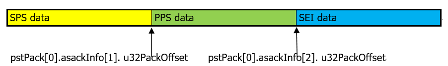
Taking H.264 as an example to introduce the code stream structure stored in pstPack[0], the corresponding information of pstPack[0] is as follows:
pstPack[0].u32DataNum=3,
pstPack[0].stPackInfo[0].u32PackType.enH264EType=E_MI_VENC_H264E_NALU_SPS,
pstPack[0].stPackInfo[1].u32PackType.enH264EType=E_MI_VENC_H264E_NALU_PPS,
pstPack[0].stPackInfo[2].u32PackType.enH264EType=E_MI_VENC_H264E_NALU_SEI ;
The pstPack[0] contains three NALU packages, including SPS/PPS/SEI, as shown in the figure below:
-
Tiramisu platform supports decoding, so it can encoding and decoding in a same case, in that case, the packet obtained from MI_VENC_GetStream needs to be ensured if it is a complete frame. If the answer is yes, send the packet to the decoder directly. If not, combine multiple packets into a complete frame and send it to vdec for decoding. Judging whether the packet is a complete frame through the bFrameEnd flag of MI_VENC_Pack_t. If it is 1, it means yes, if it is 0, it is divided into multiple packets.
-
-
Example
MI_S32 VencGetH264Stream()
{
    MI_S32 i;
    MI_S32 s32Ret;
    MI_S32 s32VencFd;
    MI_U32 u32FrameIdx = 0;
    MI_VENC_DEV VeDev = MI_VENC_DEV_ID_H264_H265_0;
    MI_VENC_CHN VeChn = 0;
    MI_VENC_ChnStat_t stStat;
    MI_VENC_Stream_t stStream;
    fd_set read_fds;
    FILE* pFile=NULL;

    pFile = fopen("stream.h264","wb");
    if (pFile == NULL)
    {
        return E_MI_ERR_FAILED;
    }
    s32VencFd = MI_VENC_GetFd(VeDev, VeChn);
    do{
        FD_ZERO(&read_fds);
        FD_SET(s32VencFd, &read_fds);
        s32Ret = select(s32VencFd+1, &read_fds, NULL, NULL, NULL);
        if (s32Ret < 0)
        {
            printf("select err\n");
            return E_MI_ERR_FAILED;
        }
        else if (0 == s32Ret)
        {
            printf("timeout\n");
            return E_MI_ERR_FAILED;
        }
        else
        {
            if (FD_ISSET(s32VencFd, &read_fds))
            {
                s32Ret = MI_VENC_Query(VeDev, VeChn, &stStat);
                if (s32Ret != MI_SUCCESS)
                {
                    return E_MI_ERR_FAILED;
                }
    /*******************************************************
    suggest to check both u32CurPacks and u32LeftStreamFrames at
    the same time,for example:
                if (0 == stStat.u32CurPacks || 0 == stStat.u32LeftStreamFrames)
                {
                    continue;
                }
    *******************************************************/
                if (0 == stStat.u32CurPacks)
                {
                    continue;
                }
                stStream.pstPack = (MI_VENC_Pack_t*)malloc(sizeof(MI_VENC_Pack_t)*stStat.u32CurPacks);
                if (NULL == stStream.pstPack)
                {
                    return E_MI_ERR_FAILED;
                }
                stStream.u32PackCount = stStat.u32CurPacks;
                s32Ret = MI_VENC_GetStream(VeDev, VeChn, &stStream, -1);
                if (MI_SUCCESS != s32Ret)
                {
                    free(stStream.pstPack);
                    stStream.pstPack = NULL;
                    return E_MI_ERR_FAILED;
                }
                for (i=0; i<stStream.u32PackCount; i++)
                {
                    fwrite(stStream.pstPack[i].pu8Addr+stStream.pstPack[i].u32Offset, 1,
                        stStream.pstPack[i].u32Len-stStream.pstPack[i].u32Offset, pFile);
                }
                s32Ret = MI_VENC_ReleaseStream(VeDev, VeChn, &stStream);
                if (MI_SUCCESS != s32Ret)
                {
                    free(stStream.pstPack);
                    stStream.pstPack=NULL;
                    return E_MI_ERR_FAILED;
                }
                free(stStream.pstPack);
                stStream.pstPack = NULL;
            }
        }
        u32FrameIdx++;
    }while(u32FrameIdx<0xff);
    fclose(pFile);

    return s32Ret;
}
2.13. MI_VENC_ReleaseStream
-
Description
Release stream buffer.
-
Syntax
MI_S32 MI_VENC_ReleaseStream(MI_VENC_DEV VeDev, MI_VENC_CHN VeChn, MI_VENC_Stream_t *pstStream); -
Parameter
Parameter Description Input/Output VeDev Encode device number Input VeChn Encode channel number. Value range: [0, VENC_MAX_CHN_NUM). Input pstStream Encode stream structure pointer. Input -
Return Value
-
MI_SUCCESS: Successful
-
Not MI_SUCCESS: Failed, see Error Code for details.
-
-
Requirement
-
Header files: mi_venc.h, mi_venc_datatype.h
-
Library file: libmi_venc.a / libmi_venc.so
-
-
Note
-
If the channel is not created, the error code MI_ERR_VENC_UNEXIST is returned.
-
If pstStream is null, the error code MI_ERR_VENC_NULL_PTR is returned.
-
This interface should be MI_VENC_GetStream Paired and used, the user must release the acquired code stream cache in time after obtaining the code stream, otherwise the code stream may be caused. Buffer Full, affecting the encoder encoding, and the user must release the already acquired stream buffer in the order in which they were first released first.
-
After the code channel is reset, all unreleased stream packets are invalid and cannot be used or released.
-
Releasing an invalid stream will return MI_ERR_VENC_ILLEGAL_PARAM.
-
-
Example
Please refer to MI_VENC_GetStream Example.
2.14. MI_VENC_InsertUserData
-
Description
Insert user data. The user applies for a space, fills in the custom information, and passes in the corresponding pointer and data length. The NAL of the next SEI (before the latest code stream packet) will have the corresponding information. Only the last unvalid user data is saved internally in the SDK.
-
Syntax
MI_S32 MI_VENC_InsertUserData(MI_VENC_DEV VeDev, MI_VENC_CHN VeChn, MI_U8 *pu8Data,MI_U32 u32Len); -
Parameter
Parameter Description Input/Output VeDev Encode device number Input VeChn Encode channel number. Value range: [0, VENC_MAX_CHN_NUM). Input pu8Data User data pointer. Input u32Len User data length. Value range: (0,1024), in bytes. Input -
Return Value
-
MI_SUCCESS: Successful
-
Not MI_SUCCESS: Failed, see Error Code for details.
-
-
Requirement
-
Header files: mi_venc.h, mi_venc_datatype.h
-
Library file: libmi_venc.a / libmi_venc.so
-
-
Note
-
If the channel is not created, it returns a failure.
-
In case of pu8Data, if it is empty, it will return failure.
-
Insertion of user data only supports H.264/H.265/AV1.
-
For H.264/H.265/AV1 protocol channel, the size of each segment of user data does not exceed 1k bytes, or this interface will return an error. Each piece of user data is inserted as an SEI package before the latest code stream package. After a certain segment of user data packet is encoded and sent, the memory space for buffering this segment of user data in the H.264/H.265/AV1 channel is cleared to store new user data.
-
-
Example
MI_S32 VencInsertUserData()
{
    MI_S32 s32Ret;
    MI_VENC_DEV VeDev = MI_VENC_DEV_ID_H264_H265_0;
    MI_VENC_CHN VeChn = 0;
    MI_U8 au8UserData[]="sigmastar2020";
    s32Ret = MI_VENC_InsertUserData(VeDev, VeChn, au8UserData, sizeof(au8UserData));
    if (MI_SUCCESS != s32Ret)
    {
        printf("MI_VENC_InsertUserData err0x%x\n", s32Ret);
        return E_MI_ERR_FAILED;
    }

    return s32Ret;
}
2.15. MI_VENC_SetMaxStreamCnt
-
Description
Set the maximum number of cache frames for the stream.
-
Syntax
MI_S32 MI_VENC_SetMaxStreamCnt(MI_VENC_DEV VeDev, MI_VENC_CHN VeChn, MI_U32 u32MaxStrmCnt); -
Parameter
Parameter Description Input/Output VeDev Encode device number Input VeChn Encode channel number. Value range: [0, VENC_MAX_CHN_NUM). Input u32MaxStrmCnt Maximum number of stream buffer frames. The value should be greater than 0
The default value is 6Input -
Return Value
-
MI_SUCCESS: Successful
-
Not MI_SUCCESS: Failed, see Error Code for details.
-
-
Requirement
-
Header files: mi_venc.h, mi_venc_datatype.h
-
Library file: libmi_venc.a / libmi_venc.so
-
-
Note
-
This interface is used to set the maximum number of frames that can be cached in the code stream buffer of the encoding channel.
-
When cached stream frames has reached the maximum number, the image to be encoded will be discarded derectly.
-
The maximum cached streams is specified by the system when the channel is created. The default value is 6.
-
This interface can be called after the channel is created and before the code channel is destroyed. Take effect before the next frame starts encoding.
-
This interface allows multiple calls. It is recommended to set the encoding before starting the encoding. It is not recommended to dynamically adjust during the encoding process.
-
2.16. MI_VENC_GetMaxStreamCnt
-
Description
Get the maximum number of cache frames in the stream.
-
Syntax
MI_S32 MI_VENC_GetMaxStreamCnt(MI_VENC_DEV VeDev, MI_VENC_CHN VeChn, MI_U32 *pu32MaxStrmCnt); -
Parameter
Parameter Description Input/Output VeDev Encode device number Input VeChn Encode channel number. Value range: [0, VENC_MAX_CHN_NUM). Input pu32MaxStrmCnt A pointer to the maximum number of stream buffer frames. Output -
Return Value
-
MI_SUCCESS: Successful
-
Not MI_SUCCESS: Failed, see Error Code for details.
-
-
Requirement
-
Header files: mi_venc.h, mi_venc_datatype.h
-
Library file: libmi_venc.a / libmi_venc.so
-
2.17. MI_VENC_RequestIdr
-
Description
Request an IDR frame.
-
Syntax
MI_S32 MI_VENC_RequestIdr(MI_VENC_DEV VeDev, MI_VENC_CHN VeChn, MI_BOOL bInstant); -
Parameter
Parameter Description Input/Output VeDev Encode device number Input VeChn Encode channel number. Value range: [0, VENC_MAX_CHN_NUM). Input bInstant Whether to delete frames that have been encoded in the SDK but have not been taken by the user.
0: Do not delete;
1: Delete, user can immediately obtain the requested IDR frame.Input -
Return Value
-
MI_SUCCESS: Successful
-
Not MI_SUCCESS: Failed, see Error Code for details.
-
-
Requirement
-
Header files: mi_venc.h, mi_venc_datatype.h
-
Library file: libmi_venc.a / libmi_venc.so
-
-
Note
-
If the channel is not created, it returns a failure.
-
I Frame request, only support H.264/H.265/AV1 Coding protocol.
-
Since this interface is not affected by frame rate control, an IDR will be encoded when call this interface. Frequent calls will affect the stability of frame rate and bit rate.
-
When bInstant is set to 1, it will delete frames that have been encoded in the SDK but have not been taken by the user, and the user layer will see an instantaneous frame loss phenomenon.
-
-
Example
MI_S32 VencRequestIdr()
{
    MI_S32 s32Ret;
    MI_VENC_DEV VeDev = MI_VENC_DEV_ID_H264_H265_0;
    MI_VENC_CHN VeChn = 0;
    MI_BOOL bInstant;

    bInstant = TRUE;
    s32Ret = MI_VENC_RequestIdr(VeDev, VeChn, bInstant);
    if (MI_SUCCESS != s32Ret)
    {
        printf("MI_VENC_RequestIDR err0x%x\n", s32Ret);
        return E_MI_ERR_FAILED;
    }

    return s32Ret;
}
2.18. MI_VENC_GetFd
-
Description
Get the device file handle corresponding to the encoding channel. It will be called before calling select/poll to listen for encoded data, thereby reducing CPU usage compared to polling.
-
Syntax
MI_S32 MI_VENC_GetFd(MI_VENC_DEV VeDev, MI_VENC_CHN VeChn); -
Parameter
Parameter Description Input/Output VeDev Encode device number Input VeChn Encode channel number. Value range: [0, VENC_MAX_CHN_NUM). Input -
Return Value
-
Device file handle: Successful
-
Others: Failed, see Error Code for details.
-
-
Requirement
-
Header files: mi_venc.h, mi_venc_datatype.h
-
Library file: libmi_venc.a / libmi_venc.so
-
-
Example
See the example in MI_VENC_GetStream.
2.19. MI_VENC_CloseFd
-
Description
Close the device file handle corresponding to the encoding channel.
-
Syntax
MI_S32 MI_VENC_CloseFd(MI_VENC_DEV VeDev, MI_VENC_CHN VeChn); -
Parameter
Parameter Description Input/Output VeDev Encode device number Input VeChn Video encoding channel number. Value range: [0, VENC_MAX_CHN_NUM). Input -
Return Value
-
MI_SUCCESS: Successful
-
Not MI_SUCCESS: Failed, see Error Code for details.
-
-
Requirement
-
Header files: mi_venc.h, mi_venc_datatype.h
-
Library file: libmi_venc.a / libmi_venc.so
-
2.20. MI_VENC_SetRoiCfg
-
Description
Set the ROI attribute of the H.264/H.265/AV1 channel. A maximum of 16 ROI regions can be set.
-
Syntax
MI_S32 MI_VENC_SetRoiCfg(MI_VENC_DEV VeDev, MI_VENC_CHN VeChn, MI_VENC_RoiCfg_t *pstVencRoiCfg); -
Parameter
Parameter Description Input/Output VeDev Encode device number Input VeChn Encode channel number. Value range: [0, VENC_MAX_CHN_NUM). Input pstVencRoiCfg ROI region parameter pointer. Input -
Return Value
-
MI_SUCCESS: Successful
-
Not MI_SUCCESS: Failed, see Error Code for details.
-
-
Requirement
-
Header files: mi_venc.h, mi_venc_datatype.h
-
Library file: libmi_venc.a / libmi_venc.so
-
-
Chip Difference
Different chip and coding protocols have different restrictions on ROI parameters, as shown in the following table:
Chip
Codec
Alignment
bAbsQp
u32Left u32Top u32Width u32Height AbsQp RelQP Maruko H.264 16 16 16 16 Not Supported [-32,31] H.265 32 32 32 32 Not Supported [-32,31] Opera H.264 16 16 16 16 Not Supported [-32,31] H.265 32 32 32 32 Not Supported [-32,31] Souffle H.264 32 32 32 32 [12,51] [-32,31] H.265 32 32 32 32 [12,51] [-32,31] AV1 64 64 64 64 [12,51] [-32,31] Iford H.264 32 32 32 32 [12,51] [-32,31] H.265 32 32 32 32 [12,51] [-32,31] -
Note
-
This interface is used to set H.264/H.265/AV1 Protocol coding channel ROI Regional parameters, ROI Mainly by parameters 5 Parameter decision.
-
u32Index: Assume that the system supports a maximum of 16 ROI regions for each channel. The system manages ROI regions based on the index number from 0 to 15. u32Index indicates the index number of the ROI set by users. ROI regions can be superimposed on each other, and when overlays occur, ROI Priority between regions increase according to index number 0 ~ 15 in turns.
-
bEnable: specify the current ROI Whether the area is enabled.
-
bAbsQp: specify the current ROI absolute use of the area QP Way or relative QP. If multiple ROI regions are used for the same coding channel, the bAbsQp of these ROI regions must be consistent. Either absolute QP mode or relative QP mode is used for all of them, and mixing is not allowed.
-
s32Qp: when bAbsQp for True Time, s32Qp Express ROI All macroblocks within the region are used QP Value, when bAbsQp for False Time, s32Qp Express ROI Relative to all macroblocks within the region QP value.
-
tRect: specify the current ROI The position coordinates of the area and size of the area. ROI starting point coordinates of the area must be within the image range.
-
-
This interface belongs to the advanced interface. The system does not have a default. ROI The zone is enabled and the user must call this interface to start ROI.
-
This interface can be set before the code channel is destroyed and after the code channel is created. This interface takes effect when the next frame is called when it is called during encoding.
-
When this interface is called frequently and the ROI area changes or the Qp changes greatly, it will affect the convergence speed of the bit rate control and may cause bit rate instability.
-
Before calling this interface, it is recommended that call MI_VENC_GetRoiCfg first to get the ROI config of current channel.
-
-
Example
MI_S32 VencSetRoi()
{
    MI_S32 s32Ret;
    MI_VENC_RoiCfg_t stRoiCfg;
    MI_S32 index=0;
    MI_VENC_DEV VeDev = MI_VENC_DEV_ID_H264_H265_0;
    MI_VENC_CHN VeChnId=0;
    //...omit other thing
    s32Ret = MI_VENC_GetRoiCfg(VeDev, VeChnId, index, &stRoiCfg);
    if (MI_SUCCESS != s32Ret)
    {
        printf("MI_VENC_GetRoiCfg err0x%x\n", s32Ret);
        return E_MI_ERR_FAILED;
    }
    stRoiCfg.bEnable = TRUE;
    stRoiCfg.bAbsQp = FALSE;
    stRoiCfg.s32Qp = 10;
    stRoiCfg.stRect.u32Left = 16;
    stRoiCfg.stRect.u32Top = 16;
    stRoiCfg.stRect.u32Width = 16;
    stRoiCfg.stRect.u32Height = 16;
    stRoiCfg.u32Index = 0;
    s32Ret = MI_VENC_SetRoiCfg(VeDev, VeChnId, &stRoiCfg);
    if (MI_SUCCESS != s32Ret)
    {
        printf("MI_VENC_SetRoiCfg err0x%x\n", s32Ret);
        return E_MI_ERR_FAILED;
}

    return s32Ret;
}
2.21. MI_VENC_GetRoiCfg
-
Description
Get the ROI configuration properties of the H.264/H.265/AV1 channel.
-
Syntax
MI_S32 MI_VENC_GetRoiCfg(MI_VENC_DEV VeDev, MI_VENC_CHN VeChn, MI_U32 u32Index,MI_VENC_RoiCfg_t *pstVencRoiCfg); -
Parameter
Parameter Description Input/Output VeDev Encode device number Input VeChn Encode channel number. Value range: [0, VENC_MAX_CHN_NUM). Input u32Index H.264/H.265/AV1 protocol encoding channel ROI region index. Input pstVencRoiCfg Corresponds to the configuration pointer of the ROI region. Output -
Return Value
-
MI_SUCCESS: Successful
-
Not MI_SUCCESS: Failed, see Error Code for details.
-
-
Requirement
-
Header files: mi_venc.h, mi_venc_datatype.h
-
Library file: libmi_venc.a / libmi_venc.so
-
-
Note
-
This interface is used to obtain H.264/H.265/AV1 Protocol coding channel Index of ROI configuration.
-
This interface can be called before the encoding channel is destroyed and after the encoding channel is created.
-
It is recommended that the user call this interface before starting the encoding and after creating the channel, reducing the number of calls during the encoding process.
-
-
Example
Please refer to MI_VENC_SetRoiCfg Example.
2.22. MI_VENC_SetRoiBgFrameRate
-
Description
Set the non-ROI region frame rate attribute of the H.264/H.265/AV1 channel.
-
Syntax
MI_S32 MI_VENC_SetRoiBgFrameRate(MI_VENC_DEV VeDev, MI_VENC_CHN VeChn, MI_VENC_RoiBgFrameRate_t *pstRoiBgFrmRate); -
Parameter
Parameter Description Input/Output VeDev Encode device number Input VeChn Encode channel number. Value range: [0, VENC_MAX_CHN_NUM). Input pstRoiBgFrmRate Non-ROI region frame rate control parameter pointer. Input -
Return Value
-
MI_SUCCESS: Successful
-
Not MI_SUCCESS: Failed, see Error Code for details.
-
-
Requirement
-
Header files: mi_venc.h, mi_venc_datatype.h
-
Library file: libmi_venc.a / libmi_venc.so
-
-
Note
-
This interface is used to set the frame rate control parameters of the non-ROI region of the H.264/H.265/AV1 protocol encoding channel.
-
The ROI region must be enabled before calling this interface.
-
This interface belongs to the advanced interface. The system is not enabled by default. ROI The area frame rate attribute, the user must call this interface to enable.
-
This interface can be set before the code channel is destroyed and after the code channel is created. This interface takes effect when the next frame is called when it is called during encoding.
-
Input frame rate when setting channel frame rate control attribute SrcFrmRate Greater than the output frame rate DstFrmRate And DstFrmRate greater or equal to 0 Or at the same time -1.
-
It is recommended that the user call this interface before starting the encoding and after creating the channel, reducing the number of calls during the encoding process.
-
It is recommended that the user call MI_VENC_GetRoiBgFrameRate interface to get the non ROI Regional frame rate configuration of current channel before calling this interface.
-
When setting the frame rate of the non-ROI region to be lower than the ROI region, it is not recommended to use TSVC. In TSVC scenario, if the frame rate of the non-ROI region is set to be lower than the ROI region, the target frame rate of the actual encoded non-ROI region may be greater than the target frame rate configured by the user, because the base layer is non-ROI Regions cannot be encoded as pskip blocks. For example, before calling this interface to set the frame rate ratio of non ROI region to 2:1, MI_VENC_SetRefParam is also called to set the long reference frame, which will result in the actual frame rate ratio of non ROI region being less than 2:1.
-
The souffle platform does not support setting frame rate properties for non-ROI regions.
-
-
Example
MI_S32 VencSetRoiFrameRate()
{
    MI_S32 s32Ret;
    MI_VENC_RoiBgFrameRate_t stRoiBgFrameRate;
    MI_S32 index = 0;
    MI_VENC_DEV VeDev = MI_VENC_DEV_ID_H264_H265_0;
    MI_VENC_CHN VeChnId=0;

    //...omit other thing
    s32Ret = MI_VENC_GetRoiBgFrameRate (VeDev, VeChnId, &stRoiBgFrameRate);
    if (MI_SUCCESS != s32Ret)
    {
        printf("MI_VENC_GetRoiBgFrameRate err0x%x\n", s32Ret);
        return E_MI_ERR_FAILED;
    }

    //...omit other thing
    stRoiBgFrameRate.s32SrcFrmRate=30;
    stRoiBgFrameRate.s32DstFrmRate=15;
    s32Ret = MI_VENC_SetRoiBgFrameRate(VeDev, VeChnId, &stRoiBgFrameRate);
    if (MI_SUCCESS != s32Ret)
    {
        printf("MI_VENC_SetRoiBgFrameRate err0x%x\n", s32Ret);
        return E_MI_ERR_FAILED;
    }

    return s32Ret;
}
2.23. MI_VENC_GetRoiBgFrameRate
-
Description
Get the non-ROI region frame rate configuration attribute of the H.264/H.265/AV1 channel.
-
Syntax
MI_S32 MI_VENC_GetRoiBgFrameRate(MI_VENC_DEV VeDev, MI_VENC_CHN VeChn, MI_VENC_RoiBgFrameRate_t *pstRoiBgFrmRate); -
Parameter
Parameter Description Input/Output VeDev Encode device number Input VeChn Encode channel number. Value range: [0, VENC_MAX_CHN_NUM). Input pstRoiBgFrmRate Configuration pointer of non-ROI region frame rate. Output -
Return Value
-
MI_SUCCESS: Successful
-
Not MI_SUCCESS: Failed, see Error Code for details.
-
-
Requirement
-
Header files: mi_venc.h, mi_venc_datatype.h
-
Library file: libmi_venc.a / libmi_venc.so
-
-
Note
-
This interface can be called before the encoding channel is destroyed and after the encoding channel is created.
-
It is recommended that the user call this interface before starting the encoding and after creating the channel, reducing the number of calls during the encoding process.
-
The souffle platform does not support setting frame rate properties for non-ROI regions.
-
-
Example
Please refer to MI_VENC_SetRoiBgFrameRate Example.
2.24. MI_VENC_SetH264SliceSplit
-
Description
Set the slice split attribute of the H.264 channel.
-
Syntax
MI_S32 MI_VENC_SetH264SliceSplit(MI_VENC_DEV VeDev, MI_VENC_CHN VeChn, MI_VENC_ParamH264SliceSplit_t *pstSliceSplit); -
Parameter
Parameter Description Input/Output VeDev Encode device number Input VeChn Encode channel number. Value range: [0, VENC_MAX_CHN_NUM). Input pstSliceSplit H.264 code stream slice segmentation parameter pointer. Input -
Return Value
-
MI_SUCCESS: Successful
-
Not MI_SUCCESS: Failed, see Error Code for details.
-
-
Requirement
-
Header files: mi_venc.h, mi_venc_datatype.h
-
Library file: libmi_venc.a / libmi_venc.so
-
-
Note
-
This interface is used to set H.264 Protocol encoding channel code stream segmentation.
-
Slice Split attribute is mainly Two Parameter decision:
1) bSplitEnable: Whether the current frame is in progress Slice segmentation.
2) u32SliceRowCount: The number of lines of each slice in the image macro block. Slice Split according to the macro block line, and when the last few lines of the image can not reach u32SliceRowCount, the remaining macro block lines are divided into a slice.
-
Set u32SliceRowCount to an even number when the H264 encoding of the Souffle/Iford platform enables Slice segmentation.
-
The default value of bSplitEnable is false. When bSplitEnable is set to true, the u32SliceRowCount macroblock row is used as a slice to encode separately. If the channel is configured to obtain the bitstream according to the packet(bByFrame=FALSE), after each slice is encoded, the user can get the stream data of the slice. It is better not to set u32SliceRowCount too small. The smaller the u32SliceRowCount is, the more frequent the user receives the notification, resulting in greater system overhead.
-
It is recommended to call this interface after creating the channel and before starting the channel, to reduce the number of calls during the encoding process. It takes effect at the next frame.
-
Before calling this interface, it is recommended that call MI_VENC_GetH264SliceSplit first to get slicesplit config of current channel.
-
H264 encoding supports a maximum of 16 slices per frame.
-
-
Example
MI_S32 VencSetSliceSplit()
{
    MI_S32 s32Ret;
    MI_VENC_ParamH264SliceSplit_t stSlice;
    MI_VENC_DEV VeDev = MI_VENC_DEV_ID_H264_H265_0;
    MI_VENC_CHN VeChnId = 0;

    //...omit other thing
    s32Ret = MI_VENC_GetH264SliceSplit(VeDev, VeChnId, &stSlice);
    if (MI_SUCCESS != s32Ret)
    {
        printf("MI_VENC_GetH264SliceSplit err0x%x\n", s32Ret);
        return E_MI_ERR_FAILED;
    }
    stSlice.bSplitEnable = TRUE;
    stSlice.u32SliceRowCount = 8;
    s32Ret = MI_VENC_SetH264SliceSplit(VeDev, VeChnId, &stSlice);

    if(MI_SUCCESS != s32Ret)
    {
        printf("MI_VENC_SetH264SliceSplit err0x%x\n", s32Ret);
        return E_MI_ERR_FAILED;
    }

    return s32Ret;
}
2.25. MI_VENC_GetH264SliceSplit
-
Description
Get the slice split attribute of the H.264 channel
-
Syntax
MI_S32 MI_VENC_GetH264SliceSplit(MI_VENC_DEV VeDev, MI_VENC_CHN VeChn, MI_VENC_ParamH264SliceSplit_t *pstSliceSplit); -
Parameters
Parameter Description Input/Output VeDev Encode device number Input VeChn EnoEncode channel number. Value range: [0, VENC_MAX_CHN_NUM). Input pstSliceSplit H.264 stream slice splite parameter pointer. Output -
Return value
-
MI_SUCCESS: Successful
-
Not MI_SUCCESS: Failed, see Error Code for details.
-
-
Dependency
-
Header files: mi_venc.h, mi_venc_datatype.h
-
Library file: libmi_venc.a / libmi_venc.so
-
-
Note
-
This interface is used to obtain the slice segmentation attribute of the H.264 protocol encoding channel.
-
This interface can be called before the encoding channel is destroyed and after the encoding channel is created.
-
It is recommended that the user call this interface before starting the encoding and after creating the channel, reducing the number of calls during the encoding process
-
-
Example
See the example of MI_VENC_SetH264SliceSplit
2.26. MI_VENC_SetH264Trans
-
Description
Set the transform and quantized attributes of the H.264 protocol encoding channel.
-
Syntax
MI_S32 MI_VENC_SetH264Trans(MI_VENC_DEV VeDev, MI_VENC_CHN VeChn, MI_VENC_ParamH264Trans_t *pstH264Trans); -
Parameters
Parameter Description Input/Output VeDev Encode device number Input VeChn Encode channel number. Value range: [0, VENC_MAX_CHN_NUM). Input pstH264Trans The transform and quantization attribute pointer of the H.264 protocol coding channel. Input -
Return value
-
MI_SUCCESS: Successful
-
Not MI_SUCCESS: Failed, see Error Code for details.
-
-
Dependency
-
Header files: mi_venc.h, mi_venc_datatype.h
-
Library file: libmi_venc.a / libmi_venc.so
-
-
Note
-
This interface is used to set the transformation and quantization configuration of the H.264 protocol encoding channel.
-
Transform, quantization property mainly by three parameters.
1) U32IntraTransMode: Transform properties of intra predicted macroblocks. U32IntraTransMode=0 indicates support for 4x4 and 8x8 transformations of intra predicted macroblocks; U32IntraTransMode=1 indicates that only 4x4 transformation is supported for intra predicted macroblocks; U32IntraTransMode=2 indicates that only 8x8 transformation is supported for intra predicted macroblocks. Only when the encoding channel protocol is high profile, can 8x8 transformation be selected, that is, under base profile and main profile, the system only supports u32IntraTransMode=1 configuration.
2) u32InterTransMode: Transform properties of inter predicted macroblocks. u32InterTransMode=0 indicates support for 4x4 and 8x8 transformations of inter predicted macroblocks; u32InterTransMode=1 indicates that only 4x4 transformation is supported for inter predicted macroblocks; u32InterTransMode=2 indicates that only 8x8 transformation is supported for inter predicted macroblocks. Only when the encoding channel protocol is high profile, can 8x8 transformation be selected, that is, under base profile and main profile, the system only supports u32InterTransMode=1 configuration.
3) s32ChromaQpIndexOffset: For details, see the chroma_qp_index_offset of H.264 protocol.
-
This interface is a high-level interface that can be called by the user. It is not recommended to call this interface. The system has default values.
-
This interface can be set before the code channel is destroyed and after the code channel is created. When this interface is called during the encoding process, it takes effect until the next I frame.
-
It is recommended that the user call this interface before starting the encoding and after creating the channel, reducing the number of calls during the encoding process.
-
Users are advised before calling this interface, first call MI_VENC_GetH264Trans interfaces, access to pre-coded channel when the trans configuration, and then set it.
-
-
Example
MI_S32 VencSetTrans()
{
    MI_S32 s32Ret;
    MI_VENC_ParamH264Trans_t stTrans;
    MI_VENC_DEV VeDev = MI_VENC_DEV_ID_H264_H265_0;
    MI_VENC_CHN VeChnId = 0;

    //...omit other thing
    s32Ret = MI_VENC_GetH264Trans(VeDev, VeChnId, &stTrans);
    if (MI_SUCCESS != s32Ret)
    {
        printf("MI_VENC_GetH264Trans err0x%x\n", s32Ret);
        return E_MI_ERR_FAILED;
    }
    stTrans.u32IntraTransMode = 2;
    stTrans.u32InterTransMode = 2;
    stTrans.s32ChromaQpIndexOffset = 2;
    s32Ret = MI_VENC_SetH264Trans(VeDev, VeChnId, &stTrans);
    if (MI_SUCCESS != s32Ret)
    {
        printf("MI_VENC_SetH264Trans err0x%x\n", s32Ret);
        return E_MI_ERR_FAILED;
    }

    return s32Ret;
}
2.27. MI_VENC_GetH264Trans
-
Description
Obtain the transform and quantization attributes of the H.264 protocol coding channel.
-
Syntax
MI_S32 MI_VENC_GetH264Trans(MI_VENC_DEV VeDev, MI_VENC_CHN VeChn, MI_VENC_ParamH264Trans_t *pstH264Trans); -
Parameters
Parameter Description Input/Output VeDev Encode device number Input VeChn Encode channel number. Value range: [0, VENC_MAX_CHN_NUM). Input pstH264Trans The transform and quantization parameter pointer of the H.264 protocol coding channel. Output -
Return value
-
MI_SUCCESS: Successful
-
Not MI_SUCCESS: Failed, see Error Code for details.
-
-
Dependency
-
Header files: mi_venc.h, mi_venc_datatype.h
-
Library file: libmi_venc.a / libmi_venc.so
-
-
Note
-
This interface is used to obtain the transform and quantization configuration of the H.264 protocol coding channel.
-
This interface can be called before the encoding channel is destroyed and after the encoding channel is created.
-
It is recommended that the user call this interface before starting the encoding and after creating the channel, reducing the number of calls during the encoding process.
-
-
Example
See the example of MI_VENC_SetH264Trans.
2.28. MI_VENC_SetH264Entropy
-
Description
Set the entropy coding mode of the H.264 protocol coding channel.
-
Syntax
MI_S32 MI_VENC_SetH264Entropy(MI_VENC_DEV VeDev, MI_VENC_CHN VeChn, MI_VENC_ParamH264Entropy_t *pstH264EntropyEnc); -
Parameters
Parameter Description Input/Output VeChn Encode channel number. Value range: [0, VENC_MAX_CHN_NUM). Input pstH264EntropyEnc Entropy coding mode pointer of the H.264 protocol coding channel. Input -
Return value
-
MI_SUCCESS: Successful
-
Not MI_SUCCESS: Failed, see Error Code for details.
-
-
Dependency
-
Header files: mi_venc.h, mi_venc_datatype.h
-
Library file: libmi_venc.a / libmi_venc.so
-
-
Note
-
This interface is used to set the entropy coding configuration of the H.264 protocol coding channel.
-
Entropy coding attribute mainly consists of two parameters:
1) u32EntropyEncModeI: entropy coding mode I frame, u32EntropyEncModeI = 0 indicates that the I-frame coding using cavlc, u32EntropyEncModeI = 1 indicates an I frame encoding cabac used.
2) u32EntropyEncModeP: entropy encoding of P frames, u32EntropyEncModeP = 0 indicates coding P frames use cavlc, u32EntropyEncModeP = 1 indicates P-frame coding using cabac.
-
The entropy coding mode of the I frame and the entropy coding mode of the P frame can be set separately.
-
Base profile does not support cabac encoding, only supports cavlc encoding, main profile and high profile support cabac encoding and cavlc encoding.
-
Compared to the Cavlc encoding method, the Cabac encoding method requires more computation, consumes less bit rate, and has better compression efficiency.
-
This interface is a high-level interface that can be called by the user. It is not recommended to call. The system has default values. The default parameters are set according to different profiles. The default entropy encoding parameters of the system under different profiles are shown in the table below.
Profile u32EntropyEncModeI u32EntropyEncModeP Base 0 0 Main/High 1 1 -
This interface can be set before the code channel is destroyed and after the code channel is created. When this interface is called during the encoding process, it takes effect until the next I frame.
-
It is recommended that the user call this interface before starting the encoding and after creating the channel, reducing the number of calls during the encoding process.
-
It is recommended that the user call the MI_VENC_GetH264Entropy interface to obtain the Entropy configuration of the current encoding channel before calling this interface, and then set it.
- Iford does not support this interface.
-
-
Example
MI_S32 VencSetEntropy()
{
    MI_S32 s32Ret;
    MI_VENC_ParamH264Entropy_t stEntropy;
    MI_VENC_DEV VeDev = MI_VENC_DEV_ID_H264_H265_0;
    MI_VENC_CHN VeChnId = 0;

    //...omit other thing
    s32Ret = MI_VENC_GetH264Entropy(VeDev, VeChnId, &stEntropy);
    if (MI_SUCCESS != s32Ret)
    {
        printf("MI_VENC_GetH264Entropy err0x%x\n", s32Ret);
        return E_MI_ERR_FAILED;
    }
    stEntropy.u32EntropyEncModeI = 0;
    stEntropy.u32EntropyEncModeP = 0;
    s32Ret = MI_VENC_SetH264Entropy(VeDev, VeChnId, &stEntropy);
    if (MI_SUCCESS != s32Ret)
    {
        printf("MI_VENC_SetH264Entropy err0x%x\n", s32Ret);
        return E_MI_ERR_FAILED;
    }

    return s32Ret;
}
2.29. MI_VENC_GetH264Entropy
-
Description
Obtain the entropy encoding attribute of the H.264 protocol encoding channel.
-
Syntax
MI_S32 MI_VENC_GetH264Entropy(MI_VENC_DEV VeDev, MI_VENC_CHN VeChn, MI_VENC_ParamH264Entropy_t *pstH264EntropyEnc); -
Parameters
Parameter Description Input/Output VeDev Encode device number Input VeChn Encode channel number. Value range: [0, VENC_MAX_CHN_NUM). Input pstH264EntropyEnc The entropy coding attribute pointer of the H.264 protocol coding channel. Output -
Return value
-
MI_SUCCESS: Successful
-
Not MI_SUCCESS: Failed, see Error Code for details.
-
-
Dependency
-
Header files: mi_venc.h, mi_venc_datatype.h
-
Library file: libmi_venc.a / libmi_venc.so
-
-
Note
-
This interface is used to obtain the entropy coding configuration of the H.264 protocol coding channel.
-
This interface can be called before the encoding channel is destroyed and after the encoding channel is created.
-
It is recommended that the user call this interface before starting the encoding and after creating the channel, reducing the number of calls during the encoding process.
-
Iford does not support this interface.
-
-
Example
See the example of MI_VENC_SetH264Entropy.
2.30. MI_VENC_SetH265Trans
-
Description
Set the transform and quantized attributes of the H.265 protocol encoding channel.
-
Syntax
MI_S32 MI_VENC_SetH265Trans(MI_VENC_DEV VeDev, MI_VENC_CHN VeChn, MI_VENC_ParamH265Trans_t *pstH265Trans); -
Parameters
Parameter Description Input/Output VeDev Encode device number Input VeChn Encode channel number. Value range: [0, VENC_MAX_CHN_NUM). Input pstH265Trans Transform and quantization attribute pointer of the H.265 protocol coding channel. Input -
Return Value
-
MI_SUCCESS: Successful
-
Not MI_SUCCESS: Failed, see Error Code for details.
-
-
Dependency
-
Header files: mi_venc.h, mi_venc_datatype.h
-
Library file: libmi_venc.a / libmi_venc.so
-
-
Note
-
This interface is used to set the conversion and quantization configuration of the H.265 protocol encoding channel.
-
Transform, quantization property mainly by three parameters.
1) U32IntraTransMode: Transform properties of intra predicted macroblocks. U32IntraTransMode=0 indicates support for 4x4 and 8x8 transformations of intra predicted macroblocks; U32IntraTransMode=1 indicates that only 4x4 transformation is supported for intra predicted macroblocks; U32IntraTransMode=2 indicates that only 8x8 transformation is supported for intra predicted macroblocks. Only when the encoding channel protocol is high profile, can 8x8 transformation be selected, that is, under base profile and main profile, the system only supports u32IntraTransMode=1 configuration.
2) u32InterTransMode: Transform properties of inter predicted macroblocks. u32InterTransMode=0 indicates support for 4x4 and 8x8 transformations of inter predicted macroblocks; u32InterTransMode=1 indicates that only 4x4 transformation is supported for inter predicted macroblocks; u32InterTransMode=2 indicates that only 8x8 transformation is supported for inter predicted macroblocks. Only when the encoding channel protocol is high profile, can 8x8 transformation be selected, that is, under base profile and main profile, the system only supports u32InterTransMode=1 configuration.
3) s32ChromaQpIndexOffset: For details, see the slice_cb_qp_offset and slice_cr_qp_offset of H.265 protocol.
-
This interface is a high-level interface that can be called by the user. It is not recommended to call this interface. The system has default values.
-
This interface can be set before the code channel is destroyed and after the code channel is created. When this interface is called during the encoding process, it takes effect until the next I frame.
-
It is recommended that the user call this interface before starting the encoding and after creating the channel, reducing the number of calls during the encoding process.
-
It is recommended that the user call the MI_VENC_GetH265Trans interface before calling this interface.
-
-
Example
MI_S32 H265SetTrans()
{
    MI_S32 s32Ret;
    MI_VENC_ParamH265Trans_t stTrans;
    MI_VENC_DEV VeDev = MI_VENC_DEV_ID_H264_H265_0;
    MI_VENC_CHN VeChnId = 0;

    //...omit other thing
    s32Ret = MI_VENC_GetH265Trans(VeDev, VeChnId, &stTrans);
    if (MI_SUCCESS != s32Ret)
    {
        printf("MI_VENC_GetH265Trans err0x%x\n", s32Ret);
        return E_MI_ERR_FAILED;
    }
    stTrans.u32IntraTransMode = 2;
    stTrans.u32InterTransMode = 2;
    stTrans.s32ChromaQpIndexOffset = 2;
    s32Ret = MI_VENC_SetH265Trans(VeDev, VeChnId, &stTrans);
    if (MI_SUCCESS != s32Ret)
    {
        printf("MI_VENC_SetH265Trans err0x%x\n", s32Ret);
        return E_MI_ERR_FAILED;
    }

    return s32Ret;
}
2.31. MI_VENC_GetH265Trans
-
Description
Obtain the transform and quantization attributes of the H.265 protocol coding channel.
-
Syntax
MI_S32 MI_VENC_GetH265Trans(MI_VENC_DEV VeDev, MI_VENC_CHN VeChn, MI_VENC_ParamH265Trans_t *pstH265Trans); -
Parameters
Parameter Description Input/Output VeDev Encode device number Input VeChn Encode channel number. Value range: [0, VENC_MAX_CHN_NUM). Input pstH265Trans The transform and quantization parameter pointer of the H.265 protocol coding channel. Output -
Return Value
-
MI_SUCCESS: Successful
-
Not MI_SUCCESS: Failed, see Error Code for details.
-
-
Dependency
-
Header files: mi_venc.h, mi_venc_datatype.h
-
Library file: libmi_venc.a / libmi_venc.so
-
-
Note
-
This interface is used to obtain the transform and quantization configuration of the H.265 protocol coding channel.
-
This interface can be called before the encoding channel is destroyed and after the encoding channel is created.
-
It is recommended that the user call this interface before starting the encoding and after creating the channel, reducing the number of calls during the encoding process.
-
-
Example
See the example of MI_VENC_SetH265Trans
2.32. MI_VENC_SetH264Dblk
-
Description
Set the deblocking type of the H.264 protocol encoding channel.
-
Syntax
MI_S32 MI_VENC_SetH264Dblk(MI_VENC_DEV VeDev, MI_VENC_CHN VeChn, MI_VENC_ParamH264Dblk_t *pstH264Dblk); -
Parameters
Parameter Description Input/Output VeDev Encode device number Input VeChn Encode channel number. Value range: [0, VENC_MAX_CHN_NUM). Input pstH264Dblk Deblocking parameter pointer of the H.264 protocol encoding channel. Input -
Return Value
-
MI_SUCCESS: Successful
-
Not MI_SUCCESS: Failed, see Error Code for details.
-
-
Dependency
-
Header files: mi_venc.h, mi_venc_datatype.h
-
Library file: libmi_venc.a / libmi_venc.so
-
-
Note
-
This interface is used to set the Deblocking configuration of the H.264 protocol encoding channel.
-
The Deblocking attributes are mainly composed of three parameters:
1) disable_deblocking_filter_idc: For details, see the H.264 protocol.
2) Slice_alpha_c0_offset_div2: For details, see the H.264 protocol.
3) Slice_beta_offset_div2: See the H.264 protocol for the specific meaning.
-
The system disables the deblocking function by default. The default disable_deblocking_filter_idc=0, slice_alpha_c0_offset_div2=0, slice_beta_offset_div2=0.
-
If the user wants to turn off the deblocking function, set disable_deblocking_filter_idc to 1.
-
This interface can be set before the code channel is destroyed and after the code channel is created. When this interface is called during the encoding process, it takes effect until the next frame.
-
It is recommended that the user call this interface before starting the encoding and after creating the channel, reducing the number of calls during the encoding process.
-
It is recommended that the user call the MI_VENC_GetH264Dblk interface before calling this interface to get the Dblk configuration and then set.
-
-
Example
MI_S32 VencSetDblk()
{
    MI_S32 s32Ret;
    MI_VENC_ParamH264Dblk_t    stDblk;
    MI_VENC_DEV VeDev = MI_VENC_DEV_ID_H264_H265_0;
    MI_VENC_CHN VeChnId = 0;

    //...omit other thing
    s32Ret = MI_VENC_GetH264Dblk(VeDev, VeChnId, &stDblk);
    if (MI_SUCCESS != s32Ret)
    {
        printf("MI_VENC_GetH264Dblk err0x%x\n", s32Ret);
        return E_MI_ERR_FAILED;
    }
    stDblk.disable_deblocking_filter_idc = 0;
    stDblk.slice_alpha_c0_offset_div2 = 6;
    stDblk.slice_beta_offset_div2 = 5;
    s32Ret = MI_VENC_SetH264Dblk(VeDev, VeChnId, &stDblk);
    if (MI_SUCCESS != s32Ret)
    {
        printf("MI_VENC_SetH264Dblk err0x%x\n", s32Ret);
        return E_MI_ERR_FAILED;
    }

    return s32Ret;
}
2.33. MI_VENC_GetH264Dblk
-
Description
Get the deblocking type of the H.264 protocol encoding channel.
-
Syntax
MI_S32 MI_VENC_GetH264Dblk(MI_VENC_DEV VeDev, MI_VENC_CHN VeChn, MI_VENC_ParamH264Dblk_t *pstH264Dblk); -
Parameters
Parameter Description Input/Output VeDev Encode device number Input VeChn Encode channel number. Value range: [0, VENC_MAX_CHN_NUM). Input pstH264Dblk The dblk attribute pointer of the H.264 protocol encoding channel. Output -
Return Value
-
MI_SUCCESS: Successful
-
Not MI_SUCCESS: Failed, see Error Code for details.
-
-
Dependency
-
Header files: mi_venc.h, mi_venc_datatype.h
-
Library file: libmi_venc.a / libmi_venc.so
-
-
Note
-
This interface is used to obtain the Deblocking configuration of the H.264 protocol encoding channel.
-
This interface can be called before the encoding channel is destroyed and after the encoding channel is created.
-
It is recommended that the user call this interface before starting the encoding and after creating the channel, reducing the number of calls during the encoding process.
-
-
Example
See the example of MI_VENC_SetH264Dblk
2.34. MI_VENC_SetH265Dblk
-
Description
Set the Deblocking type of the H.265 protocol encoding channel.
-
Syntax
MI_S32 MI_VENC_SetH265Dblk(MI_VENC_DEV VeDev, MI_VENC_CHN VeChn, MI_VENC_ParamH265Dblk_t *pstH265Dblk); -
Parameters
Parameter Description Input/Output VeDev Encode device number Input VeChn Encode channel number. Value range: [0, VENC_MAX_CHN_NUM). Input pstH265Dblk H.265 Deblocking parameter pointer of the protocol coding channel. Input -
Return Value
-
MI_SUCCESS: Successful
-
Not MI_SUCCESS: Failed, see Error Code for details.
-
-
Dependency
-
Header files: mi_venc.h, mi_venc_datatype.h
-
Library file: libmi_venc.a / libmi_venc.so
-
-
Note
-
This interface is used to set the channel coding H.265 protocol configuration Deblocking
-
The Deblocking attributes are mainly composed of three parameters:
1) disable_deblocking_filter_idc: For details, see the slice_deblocking_filter_disabled_flag of H.265 Protocol.
2) slice_tc_offset_div2: For details, see H.265 Protocol.
3) slice_beta_offset_div2: For details, see H.265 protocol.
-
The system disables the deblocking function by default. The default disable_deblocking_filter_idc=0, slice_tc_offset_div2=0, slice_beta_offset_div2=0.
-
If the user wants to turn off the deblocking function, set disable_deblocking_filter_idc to 1.
-
This interface can be set before the code channel is destroyed and after the code channel is created. When this interface is called during the encoding process, it takes effect until the next frame.
-
It is recommended that the user call this interface before starting the encoding and after creating the channel, reducing the number of calls during the encoding process.
-
It is recommended that the user call the MI_VENC_GetH265Dblk interface to get the Deblocking configuration before calling this interface.
-
-
Example
See MI_VENC_SetH264Dblk Example.
2.35. MI_VENC_GetH265Dblk
-
Description
Get the Deblocking type of the H.265 protocol encoding channel.
-
Syntax
MI_S32 MI_VENC_GetH265Dblk(MI_VENC_DEV VeDev, MI_VENC_CHN VeChn, MI_VENC_ParamH265Dblk_t *pstH265Dblk); -
Parameters
Parameter Description Input/Output VeDev Encode device number Input VeChn Encode channel number. Value range: [0, VENC_MAX_CHN_NUM). Input pstH265Dblk H.265 Deblocking channel coding protocol attribute pointer. Output -
Return Value
-
MI_SUCCESS: Successful
-
Not MI_SUCCESS: Failed, see Error Code for details.
-
-
Dependency
-
Header files: mi_venc.h, mi_venc_datatype.h
-
Library file: libmi.a
-
-
Note
-
This interface is used to obtain the Deblocking configuration of the H.265 protocol encoding channel.
-
This interface can be called before the encoding channel is destroyed and after the encoding channel is created.
-
It is recommended that the user call this interface before starting the encoding and after creating the channel, reducing the number of calls during the encoding process.
-
-
Example
See the example of MI_VENC_SetH264Dblk
2.36. MI_VENC_SetH264Vui
-
Description
Set the VUI parameter of the H.264 protocol encoding channel.
-
Syntax
MI_S32 MI_VENC_SetH264Vui(MI_VENC_DEV VeDev, MI_VENC_CHN VeChn, MI_VENC_ParamH264Vui_t *pstH264Vui); -
Parameters
Parameter Description Input/Output VeDev Encode device number Input VeChn Encode channel number. Value range: [0, VENC_MAX_CHN_NUM). Input pstH264Vui The VUI parameter pointer of the H.264 protocol encoding channel. Input -
Return Value
-
MI_SUCCESS: Successful
-
Not MI_SUCCESS: Failed, see Error Code for details.
-
-
Dependency
-
Header files: mi_common.h, mi_venc.h
-
Library file: libmi_venc.a / libmi_venc.so
-
-
Note
-
This interface is used to set the VUI configuration of the H.264 protocol encoding channel.
-
This interface can be set before the code channel is destroyed and after the code channel is created. When this interface is called during the encoding process, it takes effect until the next I frame.
-
It is recommended that the user call this interface before starting the encoding and after creating the channel, reducing the number of calls during the encoding process.
-
Users are advised before calling this interface, first call MI_VENC_GetH264Vui interface to get the current channel coding VUI configuration, and then set it.
-
-
Example
MI_S32 SetVui()
{
    MI_S32 s32Ret;
    MI_VENC_ParamH264Vui_t stVui;
    MI_VENC_DEV VeDev = MI_VENC_DEV_ID_H264_H265_0;
    MI_VENC_CHN VeChnId = 0;

    //...omit other thing
    s32Ret = MI_VENC_GetH264Vui(VeDev, VeChnId, &stVui);
    if (MI_SUCCESS != s32Ret)
    {
        printf("MI_VENC_GetH264Vui err0x%x\n", s32Ret);
        return E_MI_ERR_FAILED;
    }
    stVui.stVuiTimeInfo.u8TimingInfoPresentFlag = 1;
    s32Ret = MI_VENC_SetH264Vui(VeDev, VeChnId,&stVui);
    if (MI_SUCCESS != s32Ret)
    {
        printf("MI_VENC_SetH264Vui err0x%x\n", s32Ret);
        return E_MI_ERR_FAILED;
    }

    return s32Ret;
2.37. MI_VENC_GetH264Vui
-
Description
Obtain the VUI configuration of the H.264 protocol encoding channel.
-
Syntax
MI_S32 MI_VENC_GetH264Vui(MI_VENC_DEV VeDev, MI_VENC_CHN VeChn, MI_VENC_ParamH264Vui_t *pstH264Vui); -
Parameters
Parameter Description Input/Output VeDev Encode device number Input VeChn Encode channel number. Value range: [0, VENC_MAX_CHN_NUM). Input pstH264Vui The VUI attribute pointer of the H.264 protocol encoding channel. Output -
Return Value
-
MI_SUCCESS: Successful
-
Not MI_SUCCESS: Failed, see Error Code for details.
-
-
Dependency
-
Header files: mi_venc.h, mi_venc_datatype.h
-
Library file: libmi_venc.a / libmi_venc.so
-
-
Note
-
This interface is used to obtain the VUI configuration of the H.264 protocol encoding channel.
-
This interface can be called before the encoding channel is destroyed and after the encoding channel is created.
-
It is recommended that the user call this interface before starting the encoding and after creating the channel, reducing the number of calls during the encoding process.
-
-
Example
See the example of MI_VENC_SetH264Vui
2.38. MI_VENC_SetH265Vui
-
Description
Set the VUI parameter of the H.265 protocol encoding channel.
-
Syntax
MI_S32 MI_VENC_SetH265Vui(MI_VENC_DEV VeDev, MI_VENC_CHN VeChn, MI_VENC_ParamH265Vui_t *pstH265Vui); -
Parameters
Parameter Description Input/Output VeDev Encode device number Input VeChn Encode channel number. Value range: [0, VENC_MAX_CHN_NUM). Input pstH265Vui H.265 VUI parameter pointer of the protocol coding channel. Input -
Return Value
-
MI_SUCCESS: Successful
-
Not MI_SUCCESS: Failed, see Error Code for details.
-
-
Dependency
-
Header files: mi_venc.h, mi_venc_datatype.h
-
Library file: libmi_venc.a / libmi_venc.so
-
-
Note
-
This interface is used to set the VUI configuration of the H.265 protocol encoding channel.
-
This interface can be set before the code channel is destroyed and after the code channel is created. When this interface is called during the encoding process, it takes effect until the next I frame.
-
It is recommended that the user call this interface before starting the encoding and after creating the channel, reducing the number of calls during the encoding process.
-
It is recommended that the user call the MI_VENC_GetH265Vui interface before calling this interface to obtain the VUI configuration of the current encoding channel, and then set it.
-
-
Example
See the example of MI_VENC_SetH264Vui Example
2.39. MI_VENC_GetH265Vui
-
Description
Obtain the VUI configuration of the H.265 protocol encoding channel.
-
Syntax
MI_S32 MI_VENC_GetH265Vui(MI_VENC_DEV VeDev, MI_VENC_CHN VeChn, MI_VENC_ParamH265Vui_t *pstH265Vui); -
Parameters
Parameter Description Input/Output VeDev Encode device number Input VeChn Encode channel number. Value range: [0, VENC_MAX_CHN_NUM). Input pstH265Vui H.265 VUI attribute pointer of the protocol encoding channel. Output -
Return Value
-
MI_SUCCESS: Successful
-
Not MI_SUCCESS: Failed, see Error Code for details.
-
-
Dependency
-
Header files: mi_venc.h, mi_venc_datatype.h
-
Library file: libmi_venc.a / libmi_venc.so
-
-
Note
-
This interface is used to obtain the VUI configuration of the H.265 protocol encoding channel.
-
This interface can be called before the encoding channel is destroyed and after the encoding channel is created.
-
It is recommended that the user call this interface before starting the encoding and after creating the channel, reducing the number of calls during the encoding process.
-
-
Example
See the example of MI_VENC_SetH264Vui
2.40. MI_VENC_SetH265SliceSplit
-
Description
Set the slice split attribute of H.265 channels.
-
Syntax
MI_S32 MI_VENC_SetH265SliceSplit(MI_VENC_DEV VeDev, MI_VENC_CHN VeChn, MI_VENC_ParamH265SliceSplit_t *pstSliceSplit); -
Parameters
Parameter Description Input/Output VeDev Encode device number Input VeChn Encode channel number. Value range: [0, VENC_MAX_CHN_NUM). Input pstSliceSplit H.265 code stream slice segmentation parameter pointer. Input -
Return Value
-
MI_SUCCESS: Successful
-
Not MI_SUCCESS: Failed, see Error Code for details.
-
-
Dependency
-
Header files: mi_venc.h, mi_venc_datatype.h
-
Library file: libmi_venc.a / libmi_venc.so
-
-
Note
-
This interface is used to set the split mode of the H.265 protocol coded channel code stream.
-
Slice dividing property consists of two decision parameters.
1) bSplitEnable: whether the current frame slice division.
2) u32SliceRowCount: The number of lines of each slice in the image macro block. Slice Split according to the CTU block line, and when the last few lines of the image can not reach u32SliceRowCount, the remaining macro block lines are divided into a slice.
-
When Slice splitting is enabled for H265, u32SliceRowCount must be set to an even number.
-
This interface belongs to the advanced interface. The user can call it selectively. It is recommended not to call. The default bSplitEnable is false. This interface can be set before the code channel is destroyed and after the code channel is created. This interface takes effect when the next frame is called when it is called during encoding.
-
It is recommended that the user call this interface before starting the encoding and after creating the channel, reducing the number of calls during the encoding process.
-
It is recommended that the user call the MI_VENC_GetH265SliceSplit interface to obtain the sliceplit configuration of the current channel before calling this interface, and then set it.
-
H265 supports a maximum of 16 slices per frame.
-
-
Example
See the example of MI_VENC_SetH264SliceSplit
2.41. MI_VENC_GetH265SliceSplit
-
Description
Get the slice split attribute of H.265 channel.
-
Syntax
MI_S32 MI_VENC_GetH265SliceSplit(MI_VENC_DEV VeDev, MI_VENC_CHN VeChn, MI_VENC_ParamH265SliceSplit_t *pstSliceSplit); -
Parameters
Parameter Description Input/Output VeDev Encode device number Input VeChn Encode channel number. Value range: [0, VENC_MAX_CHN_NUM). Input pstSliceSplit H.265 code stream slice segmentation parameter pointer. Output -
Return Value
-
MI_SUCCESS: Successful
-
Not MI_SUCCESS: Failed, see Error Code for details.
-
-
Dependency
-
Header files: mi_venc.h, mi_venc_datatype.h
-
Library file: libmi_venc.a / libmi_venc.so
-
-
Note
-
This interface is used to obtain the slice split attribute of the H.265 protocol code channel.
-
This interface can be called before the encoding channel is destroyed and after the encoding channel is created.
-
It is recommended that the user call this interface before starting the encoding and after creating the channel, reducing the number of calls during the encoding process.
-
-
Example
See the example of MI_VENC_SetH264SliceSplit
2.42. MI_VENC_SetJpegParam
-
Description
Set advanced parameters for the JPEG protocol encoding channel.
-
Syntax
MI_S32 MI_VENC_SetJpegParam(MI_VENC_DEV VeDev, MI_VENC_CHN VeChn,MI_VENC_ParamJpeg_t *pstJpegParam); -
Parameters
Parameter Description Input/Output VeDev Encode device number Input VeChn Encode channel number. Value range: [0, VENC_MAX_CHN_NUM). Input pstJpegParam The advanced parameter pointer of JPEG protocol encoding channel. Input -
Return Value
-
MI_SUCCESS: Successful
-
Not MI_SUCCESS: Failed, see Error Code for details.
-
-
Dependency
-
Header files: mi_venc.h, mi_venc_datatype.h
-
Library file: libmi_venc.a / libmi_venc.so
-
-
Note
-
This interface is used to set advanced parameters of the JPEG protocol encoding channel.
-
The advanced parameters are mainly composed of 4 parameters:
1) u32Qfactor: The quantization table factor range is [1,99]. The larger the u32Qfactor is, the smaller the quantization coefficient in the quantization table is, the better the image quality will be, and the lower the compression ratio. Similarly the smaller the u32Qfactor is, the greater the quantization coefficients in the quantization table, the image quality will be obtained even worse, while a higher code compression rate. See the RFC2435 standard for the relationship between the specific u32Qfactor and the quantization table.
2) au8YQt [64], au8CbCrQt [64]: corresponding to two quantization table space, by which the user can two sets a quantization table of user parameters.
3) u32McuPerEcs: Each Ecs contains much Mcu. The system mode u32MCUPerECS=0 indicates that all MCUs of the current frame are encoded as one ECS. The minimum value of u32MCUPerECS is 0, and the maximum value does not exceed (picwidth+15)>>4x(picheight+15)>>4x2. This parameter is not supported yet.
-
This interface can be set before the code channel is destroyed and after the code channel is created. When this interface is called during the encoding process, it will take effect when the next frame is encoded.
-
It is recommended that the user call this interface before starting the encoding and after creating the channel, reducing the number of calls during the encoding process.
-
Users are advised before calling this interface, first call MI_VENC_GetJpegParam interface to obtain when the front channel coding JpegParam configuration, and then set it.
-
-
Example
MI_S32 SetJpegParam()
{
    MI_S32 s32Ret;
    MI_VENC_ParamJpeg_t stParamJpeg;
    MI_VENC_DEV VeDev = MI_VENC_DEV_ID_JPEG_0;
    MI_VENC_CHN VeChnId = 0;
    int i;

    //...omit other thing
    s32Ret = MI_VENC_GetJpegParam(VeDev, VeChnId, &stParamJpeg);
    if (MI_SUCCESS != s32Ret)
    {
        printf("MI_VENC_GetJpegParam err0x%x\n", s32Ret);
        return E_MI_ERR_FAILED;
    }
    for (i = 0; i < 64; i++)
    {
        stParamJpeg.au8YQt[i] = 16;
        stParamJpeg.au8CbCrQt[i] = 17;
    }
    s32Ret=MI_VENC_SetJpegParam(VeDev, VeChnId, &stParamJpeg);
    if (MI_SUCCESS != s32Ret)
    {
        printf("MI_VENC_SetJpegParam err0x%x\n",s32Ret);
        return E_MI_ERR_FAILED;
    }

    return s32Ret;
}
2.43. MI_VENC_GetJpegParam
-
Description
Get the advanced parameter configuration of the JPEG protocol encoding channel.
-
Syntax
MI_S32 MI_VENC_GetJpegParam(MI_VENC_DEV VeDev, MI_VENC_CHN VeChn, MI_VENC_ParamJpeg_t *pstJpegParam); -
Parameters
Parameter Description Input/Output VeDev Encode device number Input VeChn Encode channel number. Value range: [0, VENC_MAX_CHN_NUM). Input pstJpegParam Advanced parameter configuration pointer of the Jpeg protocol encoding channel. Output -
Return Value
-
MI_SUCCESS: Successful
-
Not MI_SUCCESS: Failed, see Error Code for details.
-
-
Dependency
-
Header files: mi_venc.h, mi_venc_datatype.h
-
Library file: libmi_venc.a / libmi_venc.so
-
-
Note
-
This interface is used to obtain the advanced parameter configuration of the JPEG protocol encoding channel.
-
This interface can be called before the encoding channel is destroyed and after the encoding channel is created.
-
It is recommended that the user call this interface before starting the encoding and after creating the channel, reducing the number of calls during the encoding process.
-
-
Example
See the example of MI_VENC_SetJpegParam
2.44. MI_VENC_SetRcParam
-
Description
Set advanced parameters for the code channel rate controller.
-
Syntax
MI_S32 MI_VENC_SetRcParam(MI_VENC_DEV VeDev, MI_VENC_CHN VeChn, MI_VENC_RcParam_t *pstRcParam); -
Parameters
Parameter Description Input/Output VeDev Encode device number Input VeChn Encode channel number. Value range: [0, VENC_MAX_CHN_NUM). Input pstRcParam Advanced parameter pointer for encoding channel rate controllers. Input -
Return Value
-
MI_SUCCESS: Successful
-
Not MI_SUCCESS: Failed, see Error Code for details.
-
-
Dependency
-
Header files: mi_venc.h, mi_venc_datatype.h
-
Library file: libmi_venc.a / libmi_venc.so
-
-
Chip Difference
The rate control algorithms supported by different chips and different coding protocols are different, as shown in the following table:
Chip H.264 H.265 JPEG AV1 Maruko FIXQP/CBR/VBR/AVBR FIXQP/CBR/VBR/AVBR FIXQP/CBR Not Supported Opera FIXQP/CBR/VBR/AVBR FIXQP/CBR/VBR/AVBR FIXQP/CBR/VBR Not Supported Souffle FIXQP/CBR/VBR/AVBR/CVBR FIXQP/CBR/VBR/AVBR/CVBR FIXQP/CBR/VBR FIXQP/CBR/VBR/AVBR/CVBR Iford FIXQP/CBR/VBR/AVBR/CVBR FIXQP/CBR/VBR/AVBR/CVBR FIXQP/CBR/VBR Not Supported -
Note
-
The advanced parameters of the coded channel rate controller have default values, rather than having to call this interface to start the code channel.
-
It is recommended that the user first call the MI_VENC_GetRcParam interface to obtain the RC advanced parameters, then modify the corresponding parameters, and then call this interface to set the advanced parameters.
-
The RC advanced parameters now only support H.264/H.265/AV1/Mjpeg rate control modes. The parameters stParamCbr/stParamVBR/stParamAvbr/stParamCvbr/stParamFixQp are common to H.264/H.265/AV1.
-
The advanced parameters of the rate controller u32ThrdI[RC_TEXTURE_THR_SIZE], u32ThrdP[RC_TEXTURE_THR_SIZE] and u32RowQpDelta are not supported yet.
-
The CBR parameters are as follows:
1) u32MaxIPProp: CBR advanced parameter, which represents the maximum IP ratio. The IP ratio represents the ratio of the average number of bits between the I frames and the P frames. It is mainly used to limit the I frame size under still complex scenes. When u32MaxIPProp is adjusted to be small, the I frame is blurred and the P frame is clear. Under normal circumstances, it is not recommended to constrain the IP size ratio to avoid breathing effects and bit rate fluctuations. When set to 0, u32MaxIPProp will not take effect. In a scenario where the I frame size is constrained, u32MaxIPProp can be set according to the dependency on the I frame size fluctuation.
2) u32MaxQp&u32MinQp: CBR advanced parameters, which represent the maximum QP and minimum QP of the P frame. This clamp has the strongest effect, and all other adjustments to the imageQP, such as macroblock rate control, are ultimately constrained to this maximum QP and minimum QP. The default value is 12 for u32MinQp is 12, and 48 for u32MaxQp. It is recommended not to change this group of parameters without special requirements for quality.
3) u32MaxIQp&u32MinIQp: CBR advanced parameters, which represent the maximum QP and minimum QP of the I frame. This clamp has the strongest effect, and all other adjustments to the imageQP, such as macroblock rate control, are ultimately constrained to this maximum QP and minimum QP. The default value is 12 for u32MinQp, and 48 for u32MaxQp. It is recommended not to change this group of parameters without special requirements for quality.
4) s32IPQPDelta: CBR advanced parameter, which represents the difference between the average QP value and the current I frame QP. This parameter can be a positive or negative value to adjust the excessive I frame and breathing effect. The system default value is 0. Increasing it will clear the I frame and reduce the breathing effect.
5) u32MaxISize&u32MaxPSize: CBR advanced parameters, which represent the size that the SDK attempts to limit internally before encoding the current frame. The system default value is 0, which means that this parameter does not take effect.
-
The VBR parameters are as follows:
1) S32ChangePos: VBR advanced parameter, which represents the ratio of the bit rate to the maximum bit rate when VBR starts adjusting QP. The default value of the system is 80. If there are drastic changes in content and the maximum bit rate is required, it is recommended to reduce this value and increase s32IPQPDelta. However, when the bit rate control is stable, the bit rate may be small and the quality may deviate.
2) Other parameters are the same as CBR.
-
The AVBR parameters are as follows:
1) u32MinStillPercent: AVBR advanced parameter, which represents the percentage of the bit rate relative to the set bit rate in AVBR static scenes. The system default is 35. If the image quality is poor in static scenes, it is recommended to increase this value. This will, however, take up more bitrate for encoding.
2) u32MaxStillQp: AVBR advanced parameter, which represents the maximum QP value in static scenes, and is used to ensure image quality in static scenes. This parameter does not support setting at the moment.
3) u32MotionSensitivity: AVBR advanced parameter, which represents motion sensitivity. The larger the value, the faster the bit rate control responds to the motion of the picture, but it is also more sensitive to noise.
4) AVBR relies on dynamic and static information. The encoder integrates related functions and does not require other modules to help calculate.
5) Other parameters are the same as CBR & VBR.
-
The CVBR parameters are as follows:
1) The parameter meaning is the same as CBR.
2) CVBR relies on dynamic and static information and complexity. The encoder integrates related functions and does not require other modules to help calculate.
-
The FIXQP parameters are as follows:
1) bHvsEnable: FIXQP advanced parameter, which represents each MB/CU Qp can be adjusted by complexity or not.
-
pRcParam: RC advanced parameters formulated by the user, reserved, not used at the moment.
-
It is recommended that the user call this interface before starting the encoding and after creating the channel, reducing the number of calls during the encoding process.
-
-
Example
MI_S32 VencSetRcParam()
{
    MI_S32 s32Ret;
    MI_VENC_RcParam_t stVencRcPara;
    MI_VENC_DEV VeDev = MI_VENC_DEV_ID_H264_H265_0;
    MI_VENC_CHN VeChnId = 0;

    //...omit other thing
    s32Ret = MI_VENC_GetRcParam(VeDev,VeChnId, &stVencRcPara);
    if (MI_SUCCESS != s32Ret)
    {
        printf("MI_VENC_GetRcParam err0x%x\n", s32Ret);
        return E_MI_ERR_FAILED;
    }

    stVencRcPara.stParamCbr.s32IPQPDelta = 2;
    s32Ret = MI_VENC_SetRcParam(VeDev,VeChnId, &stVencRcPara);
    if (MI_SUCCESS != s32Ret)
    {
        printf("MI_VENC_SetRcParam err0x%x\n", s32Ret);
        return E_MI_ERR_FAILED;
    }
    //...omit other thing

    return s32Ret;
}
2.45. MI_VENC_GetRcParam
-
Description
Get the channel rate control advanced parameters.
-
Syntax
MI_S32 MI_VENC_GetRcParam(MI_VENC_DEV VeDev, MI_VENC_CHN VeChn, MI_VENC_RcParam_t *pstRcParam); -
Parameters
Parameter Description Input/Output VeDev Encode device number Input VeChn Encode channel number. Value range: [0, VENC_MAX_CHN_NUM). Input pstRcParam Channel rate control parameter pointer. Output -
Return Value
-
MI_SUCCESS: Successful
-
Not MI_SUCCESS: Failed, see Error Code for details.
-
-
Dependency
-
Header files: mi_venc.h, mi_venc_datatype.h
-
Library file: libmi_venc.a / libmi_venc.so
-
-
Note
-
This interface is used to obtain advanced parameters of the H.264 encoding channel rate control. The specific meaning of each parameter, please refer to MI_VENC_RcParam_t. The parameters stParamCbr/stParamVBR/stParamAvbr/stParamCvbr/stParamFixQp are common to H.264/H.265/AV1.
-
If pstRcParam is empty, it returns a failure.
-
2.46. MI_VENC_SetRefParam
-
Description
Set the H.264/H.265/AV1 encoding channel advanced frame reference parameters.
-
Syntax
MI_S32 MI_VENC_SetRefParam(MI_VENC_DEV VeDev, MI_VENC_CHN VeChn, MI_VENC_ParamRef_t *pstRefParam) -
Parameters
Parameter Description Input/Output VeDev Encode device number Input VeChn Encode channel number. Value range: [0, VENC_MAX_CHN_NUM). Input pstRefParam H.264/H.265/AV1 coding channel advanced frame reference parameter pointer. Input -
Return Value
-
MI_SUCCESS: Successful
-
Not MI_SUCCESS: Failed, see Error Code for details.
-
-
Dependency
-
Header files: mi_venc.h, mi_venc_datatype.h
-
Library file: libmi_venc.a / libmi_venc.so
-
-
Note
-
If pstRefParam is empty, it returns a failure.
-
The default reference mode is NormalP when create H.264 / H.265 / AV1 channel. If the user needs to modify the frame reference of the encoding channel, it is recommended to call this interface before starting the encoding and after creating the channel, reducing the number of calls during the encoding process
-
When this interface is called during the encoding process, it takes effect until the next I frame.
-
If P reference previous frame(NormalP), the corresponding configuration is: bEnablePred = TRUE, u32Enhance = 0, u32Base = 1;
If All P frames reference only I , the corresponding configuration is: bEnablePred = TRUE, u32Enhance = 1, u32Base = 0;
If P reference frame that support skip half(TSVC-2), the corresponding configuration is:bEnablePred = TRUE, u32Enhance = 1, u32Base = 1;
If P reference frame that support skip quarter(TSVC-3), the corresponding configuration is: bEnablePred = TRUE, u32Enhance = 3, u32Base = 1;
For other reference mode, the value of u32Enhance can refer to the following formula: u32Enhance = gop / (number of virtual I frames + 1)-1, u32Base can take any value.
-
-
Example
MI_S32 VencSetRefParam()
{
    MI_S32 s32Ret;
    MI_VENC_ParamRef_t stRefParam;
    MI_VENC_DEV VeDev = MI_VENC_DEV_ID_H264_H265_0;
    MI_VENC_CHN VeChnId = 0;

    //...omit other thing
    s32Ret = MI_VENC_GetRefParam(VeDev, VeChn, &stRefParam);
    if (MI_SUCCESS != s32Ret)
    {
        printf("MI_VENC_GetRefParam err0x%x\n", s32Ret);
        return E_MI_ERR_FAILED;
    }

    //...omit other thing
    stRefParam.u32Base = 1;
    stRefParam.u32Enhance = 3;
    stRefParam.bEnablePred = TRUE;
    s32Ret = MI_VENC_SetRefParam(VeDev, VeChn, &stRefParam);
    if (MI_SUCCESS != s32Ret)
    {
        printf("MI_VENC_SetRefParam err0x%x\n", s32Ret);
        return E_MI_ERR_FAILED;
    }

    return s32Ret;
}
2.47. MI_VENC_GetRefParam
-
Description
Obtain the advanced frame reference parameters of the H.264/H.265/AV1 coding channel.
-
Syntax
MI_S32 MI_VENC_GetRefParam(MI_VENC_DEV VeDev, MI_VENC_CHN VeChn, MI_VENC_ParamRef_t *pstRefParam) -
Parameters
Parameter Description Input/Output VeDev Encode device number Input VeChn Encode channel number. Value range: [0, VENC_MAX_CHN_NUM). Input pstRefParam H.264/H.265/AV1 coding channel advanced frame reference parameter pointer. Output -
Return Value
-
MI_SUCCESS: Successful
-
Not MI_SUCCESS: Failed, see Error Code for details.
-
-
Dependency
-
Header files: mi_venc.h, mi_venc_datatype.h
-
Library file: libmi_venc.a / libmi_venc.so
-
-
Note
If pstRefParam is empty, it returns a failure.
-
Example
Please refer to the example of MI_VENC_SetRefParam.
2.48. MI_VENC_SetCrop
-
Description
Set the crop properties of the channel.
-
Syntax
MI_S32 MI_VENC_SetCrop (MI_VENC_DEV VeDev, MI_VENC_CHN VeChn, MI_VENC_CropCfg_t *pstCropCfg) -
Parameters
Parameter Description Input/Output VeDev Encode device number. Input VeChn Encode channel number. Value range: [0, VENC_MAX_CHN_NUM). Input pstCropCfg Channel cropping attribution pointer. Input -
Return Value
-
MI_SUCCESS: Successful
-
Not MI_SUCCESS: Failed, see Error Code for details.
-
-
Dependency
-
Header files: mi_venc.h, mi_venc_datatype.h
-
Library file: libmi_venc.a / libmi_venc.so
-
-
Chip Difference
The crop alignment parameters supported by different Chips are shown in the following table.
Chip
Alignment of (stRect.u32Left, stRect.u32Top, stRect.u32Width, stRect.u32Height)
H.264 H.265 JPEG AV1 Maruko (16,16,8,2) (16,16,8,2) (16,2,8,2) None Opera (16,16,8,2) (16,16,8,2) (16,2,8,2) None Souffle (16,16,8,2) (16,16,8,2) (16,2,8,2) (16,16,8,2) Iford (16,16,8,2) (16,16,8,2) (16,2,8,2) None -
Note
-
This interface is used to set the cropping properties of the channel.
-
This interface must be called after the channel is created and before the channel is destroyed.
-
The crop property consists of two parts:
1) bEnable: Whether the channel cropping function is enabled.
2) stRect: Crop area properties, including the coordinates of the starting point of the crop area, and the size of the crop area.
-
2.49. MI_VENC_GetCrop
-
Description
Get the crop properties of the channel.
-
Syntax
MI_S32 MI_VENC_GetCrop (MI_VENC_DEV VeDev, MI_VENC_CHN VeChn, MI_VENC_CropCfg_t *pstCropCfg) -
Parameters
Parameter Description Input/Output VeDev Encode device number Input VeChn Encode channel number. Value range: [0, VENC_MAX_CHN_NUM). Input pstCropCfg Channel cropping attribution pointer. Output -
Return Value
-
MI_SUCCESS: Successful
-
Not MI_SUCCESS: Failed, see Error Code for details.
-
-
Dependency
-
Header files: mi_venc.h, mi_venc_datatype.h
-
Library file: libmi_venc.a / libmi_venc.so
-
-
Note
-
This interface is used to obtain the cropping properties of the channel.
-
This interface must be called after the channel is created and before the channel is destroyed.
-
2.50. MI_VENC_SetFrameLostStrategy
-
Description
Set the frame loss policy when the code channel instantaneous bit rate exceeds the threshold.
-
Syntax
MI_S32 MI_VENC_SetFrameLostStrategy (MI_VENC_DEV VeDev, MI_VENC_CHN VeChn, MI_VENC_ParamFrameLost_t *pstFrmLostParam) -
Parameters
Parameter Description Input/Output VeDev Encode device number Input VeChn Encode channel number. Value range: [0, VENC_MAX_CHN_NUM). Input pstFrmLostParam The parameter pointer of the encode channel drop frame strategy. Input -
Return Value
-
MI_SUCCESS: Successful
-
Not MI_SUCCESS: Failed, see Error Code for details.
-
-
Dependency
-
Header files: mi_venc.h, mi_venc_datatype.h
-
Library file: libmi_venc.a / libmi_venc.so
-
-
Note
-
If pstFrmLostParam is empty, it returns a failure.
-
pstFrmLostParam is mainly determined by four parameters.
1) eFrmLostMode: frame lost strategy mode.
2) u32EncFrmGaps: frame lost interval.
3) bFrmLostOpen: frame lost switch.
4) u32FrmLostBpsThr: frame lost threshold.
-
This interface belongs to the advanced interface. The user can select it selectively. The system has default values. By default, the frame is lost when the instantaneous bit rate exceeds the threshold.
-
This interface provides two processing modes when the instantaneous bit rate exceeds the threshold: losing frames and encoding pskip frames. u32EncFrmGaps controls whether to lose frames uniformly or to encode pskip frames uniformly. See the figure below:
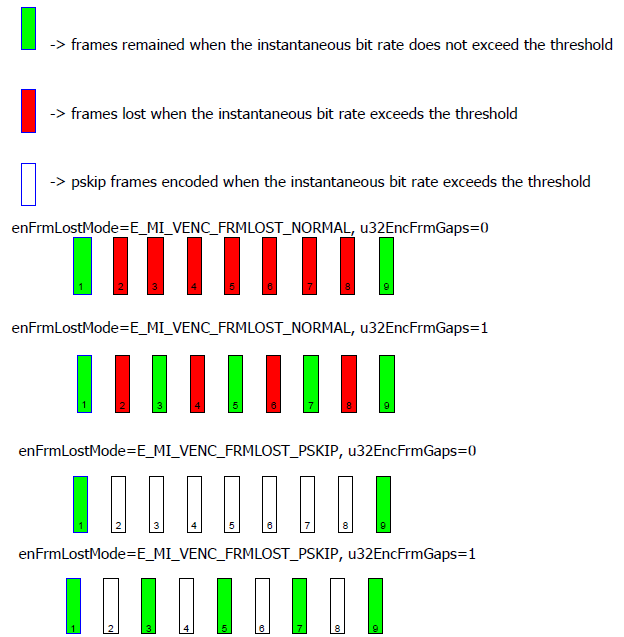
-
This interface can be set before the code channel is destroyed and after the code channel is created. This interface takes effect when the next frame is called when it is called during encoding.
-
2.51. MI_VENC_GetFrameLostStrategy
-
Description
Obtain the frame loss policy when the instantaneous bit rate of the coding channel exceeds the threshold.
-
Syntax
MI_S32 MI_VENC_GetFrameLostStrategy(MI_VENC_DEV VeDev, MI_VENC_CHN VeChn, MI_VENC_ParamFrameLost_t *pstFrmLostParam); -
Parameters
Parameter Description Input/Output VeDev Encode device number Input VeChn Encode channel number. Value range: [0, VENC_MAX_CHN_NUM). Input pstFrmLostParam The parameter pointer of frame lost strategy in encode channel Output -
Return Value
-
MI_SUCCESS: Successful
-
Not MI_SUCCESS: Failed, see Error Code for details.
-
-
Dependency
-
Header files: mi_venc.h, mi_venc_datatype.h
-
Library file: libmi_venc.a / libmi_venc.so
-
-
Note
If pstFrmLostParam is empty, it returns a failure.
2.52. MI_VENC_SetSuperFrameCfg
-
Description
Set the encoding jumbo frame configuration.
-
Syntax
MI_S32 MI_VENC_SetSuperFrameCfg(MI_VENC_DEV VeDev, MI_VENC_CHN VeChn, MI_VENC_SuperFrameCfg_t *pstSuperFrmParam); -
Parameters
Parameter Description Input/Output VeDev Encode device number Input VeChn Encode channel number. Value range: [0, VENC_MAX_CHN_NUM). input pstSuperFrmParam Encode jumbo frame configuration parameter pointer. input -
Return Value
-
MI_SUCCESS: Successful
-
Not MI_SUCCESS: Failed, see Error Code for details.
-
-
Dependency
-
Header files: mi_venc.h, mi_venc_datatype.h
-
Library file: libmi_venc.a / libmi_venc.so
-
-
Chip Diffenrence
Whether different chips support re-encoding is as follows:
Chip Whether to support Maruko Y Opera Y Souffle Y Iford Y -
Note
-
If the channel is not created, it returns a failure.
-
This interface is a high-level interface that users can optionally call. The system default value is eSuperFrmMode = E_MI_VENC_SUPERFRM_NONE.
-
This interface can be set before the code channel is destroyed and after the code channel is created.
-
When super frame mode is E_MI_VENC_SUPERFRM_NONE, MI do nothing.
-
When super frame mode is E_MI_VENC_SUPERFRM_DISCARD, MI will discard the super frame and continue encoding the next frame. MI will force to request I frame after discarding the super frame for saving memory.
-
When super frame mode is E_MI_VENC_SUPERFRM_REENCODE, MI will increase the QP of this frame by 4 and reencode it, repeating it up to 4 times. After that, regardless of whether the frame size exceeds the threshold, it will be transmitted to the user.
-
Super frame processing is mainly to prevent the picture from getting stuck due to a certain frame being too large.The unit of threshold is bit.It is recommended to set it according to the actual scene.
-
If the previous binding relationship of VENC is E_MI_SYS_BIND_TYPE_HW_RING, the super frame mode is not supported.
-
2.53. MI_VENC_GetSuperFrameCfg
-
Description
Get the encoded jumbo frame configuration.
-
Syntax
MI_S32 MI_VENC_GetSuperFrameCfg(MI_VENC_DEV VeDev, MI_VENC_CHN VeChn, MI_VENC_SuperFrameCfg_t *pstSuperFrmParam); -
Parameters
Parameter Description Input/Output VeDev Encode device number Input VeChn Encode channel number. Value range: [0, VENC_MAX_CHN_NUM). Input pstSuperFrmParam Encode jumbo frame configuration parameter pointer. Output -
Return Value
-
MI_SUCCESS: Successful
-
Not MI_SUCCESS: Failed, see Error Code for details.
-
-
Dependency
-
Header files: mi_venc.h, mi_venc_datatype.h
-
Library file: libmi_venc.a / libmi_venc.so
-
-
Note
If pstSuperFrmParam is empty, it returns a failure.
2.54. MI_VENC_SetRcPriority
-
Description
Set the priority type for rate control.
-
Syntax
MI_S32 MI_VENC_SetRcPriority(MI_VENC_DEV VeDev, MI_VENC_CHN VeChn, MI_VENC_RcPriority_e *peRcPriority); -
Parameters
Parameter Description Input/Output VeDev Encode device number. Input VeChn Encode channel number. Value range: [0, VENC_MAX_CHN_NUM). Input peRcPriority Pointer to the priority type. Input -
Return Value
-
MI_SUCCESS: Successful
-
Not MI_SUCCESS: Failed, see Error Code for details.
-
-
Dependency
-
Header file: mi_venc.h, mi_venc_datatype.h
-
Library file: libmi_venc.a / libmi_venc.so
-
-
Note
-
This interface is used to set the rate control to the target bit rate or to the high frame threshold with high priority.
-
When the rate control is high priority with the target bit rate, when the bit rate is insufficient, a large frame may be encoded to compensate the bit rate, and the oversized frame will not be reprogrammed. When the rate control is based on the jumbo frame threshold being high priority, the jumbo frame will reprogram the number of bits, which may result in insufficient bit rate.
-
This interface must be called after the code channel is created and before the code channel is destroyed.
-
This interface only supports the rate control mode of H.264/H.265/AV1 protocols.
-
2.55. MI_VENC_GetRcPriority
-
Description
Get the priority type of rate control.
-
Syntax
MI_S32 MI_VENC_GetRcPriority(MI_VENC_DEV VeDev, MI_VENC_CHN VeChn, MI_VENC_RcPriority_e *peRcPriority); -
Parameters
Parameter Description Input/Output VeDev Encode device number. Input VeChn Encode channel number. Value range: [0, VENC_MAX_CHN_NUM). Input peRcPriority Pointer to the priority type. Output -
Return Value
-
MI_SUCCESS: Successful
-
Not MI_SUCCESS: Failed, see Error Code for details.
-
-
Dependency
-
Header file: mi_venc.h, mi_venc_datatype.h
-
Library file: libmi_venc.a / libmi_venc.so
-
-
Note
This interface must be called after the code channel is created and before the code channel is destroyed.
2.56. MI_VENC_AllocCustomMap
-
Description
Allocate the memory for Custom Map used by smart encoding. The Custom Map includes QP Map and Mode Map.
-
Syntax
MI_S32 MI_VENC_ AllocCustomMap (MI_VENC_DEV VeDev, MI_VENC_CHN VeChn, MI_PHY *pstPhyAddr, void *ppCpuAddr); -
Parameters
Parameter Description Input/Output VeDev Encode device number Input VeChn Encode channel number. Value range: [0, VENC_MAX_CHN_NUM). Input pstPhyAddr Pointer to the allocated virtual physical address. Input/Output ppCpuAddr Pointer to the allocated CPU address. Input/Output -
Return Value
-
MI_SUCCESS: Successful
-
Not MI_SUCCESS: Failed, see Error Code for details.
-
-
Dependency
-
Header file: mi_venc.h, mi_venc_datatype.h
-
Library file: libmi_venc.a / libmi_venc.so
-
-
Note
-
This interface is used for allocating the memory needed by Custom Map. It returns the address of the allocated memory including the physical address and CPU address.
-
If the memory allocation fails, the pstPhyAddr or ppCpuAddr is null and a failure will be returned.
-
This interface must be called after the code channel is created and before the code channel is destroyed. The allocated memory will be free when the code channel is destroyed.
-
The Custom Map includes QP Map and Mode Map. The two types of Custom Map could be applied simultaneously.
-
QPS in QP Map are set in units of 32×32 blocks in Souffle platform for H.264 and 16×16 blocks in other platforms for H.264. The QP value for each block unit (32×32 blocks/16×16 blocks) could be set with the customer defined value. The QP Map is as illustrated below. The QP values should be successively set to the memory which is assigned for QP Map. The QP value could be set with relative or absolute value (refer to MI_VENC_SetAdvCustRcAttr). The value range is [12, 51] if absolute QP is configured, while the value range should be [0, 63] if relative QP is configured. The effective relative QP value is the configured QP value minus 32. Therefore, the effective relative value range is [-32, 31], while the effective absolute value range is [12, 51].)
-
The setting of Mode in Mode Map is also 32×32 blocks in souffle platform H.264 and 16×16 blocks in other platforms H.264. The Mode value for each block (32×32/16×16) could be set with the customer defined value. The Mode Map is as illustrated below. The Mode values should be successively set to the memory which is assigned for Mode Map.
-
Souffle platform does not support setting Mode Map, that is, the Mode Map value of Souffle platform can only be set to 0, while the Mode value of other platforms can be set to (0: not use, 1: skip mode, 2: intra mode).
-
One byte with Mode/QP value could be set every blocks(32×32/16×16). The configuration data struct is as shown below.
struct {

uint8 qp : 6;

uint8 mode : 2;

} H264CustomMapConf;
The Souffle/Iford platform H.264 is as follows:

H.264 for other platforms is as follows:

-
In H.265, the QP Map contains QPs for every 4x32x32 block. The QP value for each 4x32x32 block could be set with the customer defined value. The QP Map is as illustrated below. The QP values should be successively set to the memory which is assigned for QP Map. The QP value could be set with relative or absolute value (refer to MI_VENC_SetAdvCustRcAttr).
-
The Mode Map contains Mode value for every 4x32x32 block. The Mode value for each 4x32x32 block could be set with the customer defined value. The Mode Map is just the same as the QP Map. The Mode values should be successively set to the memory which is assigned for Mode Map.
-
Four bytes with QP/Mode value could be set every 4x32x32 blocks. The configuration data structure is as shown below. The Mode value uses 2 bits. The QP value for every 32x32 block uses 6 bits.
struct {

        uint32  sub_ctu_qp_0    :  6;

        uint32  mode  :  2;

        uint32  sub_ctu_qp_1    :  6;

        uint32  reserved_0  :  2;

        uint32  sub_ctu_qp_2    :  6;

        uint32  reserved_1       :  2;

        uint32  sub_ctu_qp_3    :  6;

        uint32  reserved_2      :  2;

} H265CustomMapConf;
-
If the last block of the effective width of the H.265 encoding is less than 32pixel, or the last block of the effective height is less than 32pixel, the Map of H.265 on the Souffle/Iford platform is organized as follows:

-
If the last block of the effective width of the H.265 encoding is less than 32pixel, or the last block of the effective height is less than 32pixel, the Map of H.265 on other platforms is organized as follows:

-
QP in QP Map shall be set in AV1 with
64*64blocks as the unit. QP value of each64*64blocks shall be the corresponding block QP value set by the user. The QP values of all these blocks form the QP table. The QP values in this table are organized in the following way. The QP values are successively filled into the memory addresses allocated for the QP Map. QP values are also entered using relative or absolute values depending on the settings. -
The Mode setting in Mode Map is also based on
64*64blocks in AV1. The Mode value of each64*64blocks adopts the corresponding block Mode value set by the user. The Mode values of all these blocks form the Mode table, which is organized in the same way as the QP values, with the Mode filling in the memory addresses allocated for the Mode Map. -
One byte with Mode/QP value could be set every blocks(
64*64). The configuration data struct is as shown below.struct { uint8 qp : 6; uint8 mode : 2; } Av1CustomMapConf;
-
2.57. MI_VENC_ApplyCustomMap
-
Description
Apply the configured Custom Map.
-
Syntax
MI_S32 MI_VENC_ApplyCustomMap (MI_VENC_DEV VeDev, MI_VENC_CHN VeChn, MI_PHY PhyAddr); -
Parameters
Parameter Description Input/Output VeDev Encode device number Input VeChn Encode channel number. Value range: [0, VENC_MAX_CHN_NUM). Input PhyAddr The allocated virtual physical address. Input -
Return Value
-
MI_SUCCESS: Successful
-
Not MI_SUCCESS: Failed, see Error Code for details.
-
-
Dependency
-
Header file: mi_venc.h, mi_venc_datatype.h
-
Library file: libmi_venc.a / libmi_venc.so
-
-
Note
-
This interface is used for applying the configuration after the customer defined Custom Map is configured into the corresponding address.
-
This interface must be called after the Custom Map is initialized or modified.
-
2.58. MI_VENC_GetLastHistoStaticInfo
-
Description
Get the output information when the latest frame is encoded.
-
Syntax
MI_S32 MI_VENC_GetLastHistoStaticInfo (MI_VENC_DEV VeDev, MI_VENC_CHN VeChn, MI_VENC_FrameHistoStaticInfo_t *ppFrmHistoStaticInfo); -
Parameters
Parameter Description Input/Output VeDev Encode device number Input VeChn Encode channel number. Value range: [0, VENC_MAX_CHN_NUM). Input ppFrmHistoStaticInfo Pointer to the address of the saved output information for the latest encoded frame. Output -
Return Value
-
MI_SUCCESS: Successful
-
Not MI_SUCCESS: Failed, see Error Code for details.
-
-
Dependency
-
Header file: mi_venc.h, mi_venc_datatype.h
-
Library file: libmi_venc.a / libmi_venc.so
-
-
Note
- This interface is not supported yet.
2.59. MI_VENC_ReleaseHistoStaticInfo
-
Description
Release the memory used for the output information when the latest frame is encoded.
-
Syntax
MI_S32 MI_VENC_ReleaseHistoStaticInfo (MI_VENC_DEV VeDev, MI_VENC_CHN VeChn); -
Parameters
Parameter Description Input/Output VeDev Encode device number Input VeChn Encode channel number. Value range: [0, VENC_MAX_CHN_NUM). Input -
Return Value
-
MI_SUCCESS: Successful
-
Not MI_SUCCESS: Failed, see Error Code for details.
-
-
Dependency
-
Header file: mi_venc.h, mi_venc_datatype.h
-
Library file: libmi_venc.a / libmi_venc.so
-
-
Note
- This interface is not supported currently.
2.60. MI_VENC_SetAdvCustRcAttr
-
Description
Set the customer defined advanced RC configuration parameters.
-
Syntax
MI_S32 MI_VENC_ SetAdvCustRcAttr (MI_VENC_DEV VeDev, MI_VENC_CHN VeChn, MI_VENC_AdvCustRcAttr_t *pstAdvCustRcAttr); -
Parameters
Parameter Description Input/Output VeDev Encode device number Input VeChn Encode channel number. Value range: [0, VENC_MAX_CHN_NUM). Input pstAdvCustRcAttr Customer defined advanced RC configuration parameter pointer. Input -
Return Value
-
MI_SUCCESS: Successful
-
Not MI_SUCCESS: Failed, see Error Code for details.
-
-
Dependency
-
Header file: mi_venc.h, mi_venc_datatype.h
-
Library file: libmi_venc.a / libmi_venc.so
-
-
Note
-
This interface is used for setting the customer defined advanced RC configuration parameters.
-
This interface must be called after the code channel is created and before the picture starts to be received.
-
After the switch of customer defined advanced RC configuration is set, the related function could be started by calling the functions MI_VENC_AllocCustomMap.
-
2.61. MI_VENC_SetInputSourceConfig
-
Description
Set H.264/H.265/AV1 input source info.
-
Syntax
MI_S32 MI_VENC_SetInputSourceConfig(MI_VENC_DEV VeDev, MI_VENC_CHN VeChn, MI_VENC_InputSourceConfig_t *pstInputSourceConfig); -
Parameters
Parameter Description Input/Output VeDev Encode device number. Input VeChn Encode channel number. Value range: [0, VENC_MAX_CHN_NUM). Input pstInputSourceConfig Pointer to input source info. Input -
Return Value
-
MI_SUCCESS: Successful
-
Not MI_SUCCESS: Failed, see Error Code for details.
-
-
Dependency
-
Header files: mi_venc.h, mi_venc_datatype.h
-
Library file: libmi_venc.a / libmi_venc.so
-
-
Note
- Not support, user no need call and pay attention to the setting.
2.62. MI_VENC_SetIntraRefresh
-
Description
Set H.264/H.265/AV1 P-frame brush Islice. When IntraResearch mode is turned on, only one IDR is present at the beginning of the encoding, and then there will be P-frame only. The advantage of enabling IntraRefresh mode is that, by scattering the original IDR coded IntraLCU/Macroblock in a number of P-frames, the size of the frames will be relatively similar, without affecting the IDR frame quality.
-
Syntax
MI_S32 MI_VENC_SetIntraRefresh(MI_VENC_DEV VeDev, MI_VENC_CHN VeChn, MI_VENC_IntraRefresh_t *pstIntraAttr); -
Parameters
Parameter Description Input/Output VeDev Encode device number Input VeChn Encode channel number. Value range: [0, VENC_MAX_CHN_NUM). Input pstIntraAttr Input Intra configuration information Input -
Return Value
-
MI_SUCCESS: Successful
-
Not MI_SUCCESS: Failed, see Error Code for details.
-
-
Dependency
-
Header file: mi_venc.h, mi_venc_datatype.h
-
Library file: libmi_venc.a / libmi_venc.so
-
-
Note
-
If the channel is not created, it returns a failure.
-
This interface must be called after the code channel is created and before the picture starts to be received.
-
u32RefreshLineNum value range: total_mb_count/gop < u32RefreshLineNum <= total_mb_count. For example: 1080P, gop = 30, mb_height = 16, value range: total_mb_count = 1088/16 = 68, total_mb_count/gop = 68/30 = 2.26, then 2.26 < u32RefreshLineNum <= 68. In order to reduce the bit rate, it is recommended that the value of u32RefreshLineNum be smaller, otherwise the P frame of the entire gop will be refreshed to Islice.
-
After setting this interface, only the first frame of the encoded bitstream is an IDR frame, which will affect the player's random decoding. Users can call MI_VENC_RequestIdr to force the generation of IDR frames.
-
-
Example
MI_S32 SetIntraRefresh()
{
    MI_S32 s32Ret;
    MI_VENC_DEV VeDev = MI_VENC_DEV_ID_H264_H265_0;
    MI_VENC_CHN VeChn = 0;
    MI_VENC_IntraRefresh_t stIntraAttr;

    //...omit other thing
    s32Ret = MI_VENC_GetIntraRefresh(VeDev, VeChnId, &stIntraAttr);
    if (MI_SUCCESS != s32Ret)
    {
        printf("MI_VENC_GetIntraRefresh err0x%x\n", s32Ret);
        return E_MI_ERR_FAILED;
    }
    stIntraAttr.bEnable = TRUE;
    stIntraAttr.u32RefreshLineNum = 2;
    stIntraAttr.u32ReqIQp = FALSE;
    s32Ret = MI_VENC_SetIntraRefresh(VeDev, VeChn, &stIntraAttr);
    if (MI_SUCCESS != s32Ret)
    {
    printf("MI_VENC_SetIntraRefresh err 0x%x\n", s32Ret);
        return E_MI_ERR_FAILED;
    }

    return s32Ret;
}
2.63. MI_VENC_GetIntraRefresh
-
Description
Get H.264/H.265/AV1 Intra Refresh Parameter
-
Syntax
MI_S32 MI_VENC_GetIntraRefresh(MI_VENC_DEV VeDev, MI_VENC_CHN VeChn, MI_VENC_IntraRefresh_t *pstIntraAttr); -
Parameters
Parameter Description Input/Output VeDev Encode device number. Input VeChn Encode channel number. Value range: [0, VENC_MAX_CHN_NUM). Input pstIntraAttr Pointer to output Intra configuration information. Output -
Return Value
-
MI_SUCCESS: Successful
-
Not MI_SUCCESS: Failed, see Error Code for details.
-
-
Dependency
-
Header file: mi_venc.h, mi_venc_datatype.h
-
Library file: libmi_venc.a / libmi_venc.so
-
-
Note
-
If the channel is not created, it returns a failure.
-
This interface must be called after the code channel is created and before the picture starts to be received.
-
-
Example
Please refer to the example of MI_VENC_SetIntraRefresh.
2.64. MI_VENC_DupChn
-
Description
Synchronize status of VENC channel.
-
Syntax
MI_S32 MI_VENC_DupChn(MI_VENC_DEV VeDev, MI_VENC_CHN VeChn) -
Parameters
Parameter Description Input/Output VeDev Encode device number Input VeChn Encode channel number. Value range: [0, VENC_MAX_CHN_NUM). Input -
Return Value
-
MI_SUCCESS: Successful
-
Not MI_SUCCESS: Failed, see Error Code for details.
-
-
Dependency
-
Header file: mi_venc.h, mi_venc_datatype.h
-
Library file: libmi_venc.a / libmi_venc.so
-
-
Note
- This interface applies only to multi-process environment such as dual OS. The venc channel is initialized in the RTK environment and used to synchronize the status of the venc channel when switching to the Linux environment.
2.65. MI_VENC_SetAv1TileSplit
-
Description
Set the tile split attribute of AV1 channels.
-
Syntax
MI_S32 MI_VENC_SetAv1TileSplit(MI_VENC_DEV VeDev, MI_VENC_CHN VeChn, MI_VENC_ParamAv1TileSplit_t *pstTileSplit); -
Parameters
Parameter Description Input/Output VeDev Encode device number Input VeChn Encode channel number. Value range: [0, VENC_MAX_CHN_NUM). Input pstTileSplit AV1 code stream tile split parameter pointer. Input -
Return Value
-
MI_SUCCESS: Successful
-
Not MI_SUCCESS: Failed, see Error Code for details.
-
-
Dependency
-
Header files: mi_venc.h, mi_venc_datatype.h
-
Library file: libmi_venc.a / libmi_venc.so
-
-
Note
-
This interface is used to set the split mode of the AV1 protocol encoded channel code stream.
-
Tile split attribute is mainly determined by two parameters.
1) bSplitEnable: Enable tile split of the current frame or not.
2) u32TileRowCount: The tile is split according to the macroblock row. u32TileRowCount indicates that the count of image macroblock row occupied by each tile. And when encoding to the last few lines of the image, less than u32TileRowCount, the remaining macroblock row are divided into a tile.
-
This interface belongs to the advanced interface. The user can call it selectively. It is recommended not to call. The default bSplitEnable is false. This interface can be set before the code channel is destroyed and after the code channel is created. This interface takes effect when the next frame is called when it is called during encoding.
-
It is recommended that the user call this interface before starting the encoding and after creating the channel, reducing the number of calls during the encoding process.
-
It is recommended that the user call the MI_VENC_GetAv1TileSplit interface to obtain the tile split configuration of the current channel before calling this interface, and then set this interface.
-
AV1 supports a maximum of 16 tiles per frame.
-
-
Example
See the example of MI_VENC_SetH264SliceSplit
2.66. MI_VENC_GetAv1TileSplit
-
Description
Get the tile split attribute of AV1 channel.
-
Syntax
MI_S32 MI_VENC_GetAv1TileSplit(MI_VENC_DEV VeDev, MI_VENC_CHN VeChn, MI_VENC_ParamAv1TileSplit_t *pstTileSplit); -
Parameters
Parameter Description Input/Output VeDev Encode device number Input VeChn Encode channel number. Value range: [0, VENC_MAX_CHN_NUM). Input pstTileSplit AV1 code stream tile split parameter pointer. Output -
Return Value
-
MI_SUCCESS: Successful
-
Not MI_SUCCESS: Failed, see Error Code for details.
-
-
Dependency
-
Header files: mi_venc.h, mi_venc_datatype.h
-
Library file: libmi_venc.a / libmi_venc.so
-
-
Note
-
This interface is used to obtain the tile split attribute of the AV1 protocol code channel.
-
This interface can be called before the encoding channel is destroyed and after the encoding channel is created.
-
It is recommended that the user call this interface before starting the encoding and after creating the channel, reducing the number of calls during the encoding process.
-
-
Example
See the example of MI_VENC_SetH264SliceSplit
2.67. MI_VENC_SetAv1Dblk
-
Description
Set the Deblocking type of the AV1 protocol encoding channel.
-
Syntax
MI_S32 MI_VENC_SetAv1Dblk(MI_VENC_DEV VeDev, MI_VENC_CHN VeChn, MI_VENC_ParamAv1Dblk_t *pstAv1Dblk); -
Parameters
Parameter Description Input/Output VeDev Encode device number Input VeChn Encode channel number. Value range: [0, VENC_MAX_CHN_NUM). Input pstAv1Dblk Deblocking parameter pointer of AV1 protocol encoding channel. Input -
Return Value
-
MI_SUCCESS: Successful
-
Not MI_SUCCESS: Failed, see Error Code for details.
-
-
Dependency
-
Header files: mi_venc.h, mi_venc_datatype.h
-
Library file: libmi_venc.a / libmi_venc.so
-
-
Note
-
This interface is used to set the Deblocking configuration of AV1 protocol encoding channel.
-
The Deblocking attributes are mainly composed of three parameters:
1) u32DblkMode: If the value is set to 0, the function is disabled. If the value is set to 1, the internal calculated Deblocking parameter is enabled (the Deblocking parameter set by the user is invalid). If the value is set to 2, the locking function is enabled and the Deblocking parameter set by the user is used.
2) u32LumaHorzLevel: For details, see the definition of loop_filter_level[0] of AV1.
3) u32LumaVertLevel: For details, see the definition of loop_filter_level[1] of AV1.
4) u32ChromaLevel: For details, see the definition of loop_filter_level[2] of AV1.
5) u32Sharpness: For details, see the definition of loop_filter_sharpness of AV1.
-
The system enables the deblocking function by default. The default u32DblkMode=1.
-
If the user wants to disable the deblocking function, set u32DblkMode to 0.
-
This interface can be set before the code channel is destroyed and after the code channel is created. When this interface is called during the encoding process, it takes effect until the next frame.
-
It is recommended that the user call this interface before starting the encoding and after creating the channel, reducing the number of calls during the encoding process.
-
It is recommended that the user call the MI_VENC_GetAv1Dblk interface to get the Deblocking configuration before calling this interface.
-
-
Example
See MI_VENC_SetH264Dblk Example.
2.68. MI_VENC_GetAv1Dblk
-
Description
Get the Deblocking type of the AV1 protocol encoding channel.
-
Syntax
MI_S32 MI_VENC_GetAv1Dblk(MI_VENC_DEV VeDev, MI_VENC_CHN VeChn, MI_VENC_ParamAv1Dblk_t *pstAv1Dblk); -
Parameters
Parameter Description Input/Output VeDev Encode device number Input VeChn Encode channel number. Value range: [0, VENC_MAX_CHN_NUM). Input pstAv1Dblk Deblocking attribute pointer of AV1 protocol encoding channel. Output -
Return Value
-
MI_SUCCESS: Successful
-
Not MI_SUCCESS: Failed, see Error Code for details.
-
-
Dependency
-
Header files: mi_venc.h, mi_venc_datatype.h
-
Library file: libmi.a
-
-
Note
-
This interface is used to obtain the Deblocking configuration of the AV1 protocol encoding channel.
-
This interface can be called before the encoding channel is destroyed and after the encoding channel is created.
-
It is recommended that the user call this interface before starting the encoding and after creating the channel, reducing the number of calls during the encoding process.
-
-
Example
See the example of MI_VENC_SetH264Dblk
2.69. MI_VENC_SetAv1Vui
-
Description
Set the VUI parameter of the AV1 protocol encoding channel.
-
Syntax
MI_S32 MI_VENC_SetAv1Vui(MI_VENC_DEV VeDev, MI_VENC_CHN VeChn, MI_VENC_ParamAv1Vui_t *pstAv1Vui); -
Parameters
Parameter Description Input/Output VeDev Encode device number Input VeChn Encode channel number. Value range: [0, VENC_MAX_CHN_NUM). Input pstAv1Vui VUI parameter pointer of the AV1 protocol encoding channel. Input -
Return Value
-
MI_SUCCESS: Successful
-
Not MI_SUCCESS: Failed, see Error Code for details.
-
-
Dependency
-
Header files: mi_venc.h, mi_venc_datatype.h
-
Library file: libmi_venc.a / libmi_venc.so
-
-
Note
-
This interface is used to set the VUI configuration of the AV1 protocol encoding channel.
-
This interface can be set before the code channel is destroyed and after the code channel is created. When this interface is called during the encoding process, it takes effect until the next I frame.
-
It is recommended that the user call this interface before starting the encoding and after creating the channel, reducing the number of calls during the encoding process.
-
It is recommended that the user call the MI_VENC_GetAv1Vui interface to obtain the VUI configuration of the current encoding channel before calling this interface, and then set this interface.
-
-
Example
See the example of MI_VENC_SetH264Vui
2.70. MI_VENC_GetAv1Vui
-
Description
Get the VUI configuration of the AV1 protocol encoding channel.
-
Syntax
MI_S32 MI_VENC_GetAv1Vui(MI_VENC_DEV VeDev, MI_VENC_CHN VeChn, MI_VENC_ParamAv1Vui_t *pstAv1Vui); -
Parameters
Parameter Description Input/Output VeDev Encode device number Input VeChn Encode channel number. Value range: [0, VENC_MAX_CHN_NUM). Input pstAv1Vui VUI attribute pointer of of the AV1 protocol encoding channel. Output -
Return Value
-
MI_SUCCESS: Successful
-
Not MI_SUCCESS: Failed, see Error Code for details.
-
-
Dependency
-
Header files: mi_venc.h, mi_venc_datatype.h
-
Library file: libmi_venc.a / libmi_venc.so
-
-
Note
-
This interface is used to obtain the VUI configuration of the AV1 protocol encoding channel.
-
This interface can be called before the encoding channel is destroyed and after the encoding channel is created.
-
It is recommended that the user call this interface before starting the encoding and after creating the channel, reducing the number of calls during the encoding process.
-
-
Example
See the example of MI_VENC_SetH264Vui
2.71. OnVencUserRcInit
-
Description
Initializes related UBR resources in the module.
-
Syntax
MI_S32 (*OnVencUserRcInit)(MI_VENC_DEV VeDev, MI_VENC_CHN VeChn, MI_VENC_UserRcChnAttr_t *pstAttr) -
Parameters
Parameter Description Input/Output VeDev Encode device number. Input VeChn Encode channel number. Value range: [0, VENC_MAX_CHN_NUM). Input pstAttr Input VENC RC configuration information. Input -
Return Value
-
MI_SUCCESS: Successful
-
Not MI_SUCCESS: Failed, the return value is user-defined.
-
-
Dependency
-
Header file: mi_venc.h, mi_venc_datatype.h
-
Library file: libmi_venc.a / libmi_venc.so
-
-
Note
- VENC calls this function once when the APP accesses UBR via MI_VENC_CreateChn or MI_VENC_SetChnAttr, and emits the corresponding channel number and properties.
-
Related Data Type and Interface
2.72. OnVencUserRcDeinit
-
Description
Deinitializes related UBR resources in the module.
-
Syntax
MI_S32 (*OnVencUserRcDeinit)(MI_VENC_DEV VeDev, MI_VENC_CHN VeChn) -
Parameters
Parameter Description Input/Output VeDev Encode device number. Input VeChn Encode channel number. Value range: [0, VENC_MAX_CHN_NUM). Input -
Return Value
-
MI_SUCCESS: Successful
-
Not MI_SUCCESS: Failed, the return value is user-defined.
-
-
Dependency
-
Header file: mi_venc.h, mi_venc_datatype.h
-
Library file: libmi_venc.a / libmi_venc.so
-
-
Note
- VENC calls this function once when the APP switch UBR RC mode or invoke MI_VENC_DestroyChn, and emits the corresponding channel number.
2.73. OnVencUserRcAttrChange
-
Description
UBR channel attribute.
-
Syntax
MI_S32 (*OnVencUserRcAttrChange)(MI_VENC_DEV VeDev, MI_VENC_CHN VeChn, MI_VENC_UserRcChnAttr_t *pstAttr) -
Parameters
Parameter Description Input/Output VeDev Encode device number. Input VeChn Encode channel number. Value range: [0, VENC_MAX_CHN_NUM). Input pstAttr Input VENC RC configuration information. Input -
Return Value
-
MI_SUCCESS: Successful
-
Not MI_SUCCESS: Failed, the return value is user-defined.
-
-
Dependency
-
Header file: mi_venc.h, mi_venc_datatype.h
-
Library file: libmi_venc.a / libmi_venc.so
-
-
Note
- When channel property is modified, such as bitrate or fps, VENC calls this function to set the modified channel property.
-
Related Data Type and Interface
2.74. OnVencUserRcCalc
-
Description
Configure the encoding properties of the current frame according to the encoding information of the previous frame.
-
Syntax
MI_S32(*OnVencUserRcCalc)(MI_VENC_DEV VeDev, MI_VENC_CHN VeChn, const MI_VENC_UserRcFrameAttr_t *pstFrameAttr, MI_VENC_UserRcEncParam_t *pstEncParam) -
Parameters
Parameter Description Input/Output VeDev Encode device number. Input VeChn Encode channel number. Value range: [0, VENC_MAX_CHN_NUM). Input pstFrameAttr Input the encoding information of the previous frame Input pstEncParam Output the current frame encoding parameter set by the user Output -
Return Value
-
MI_SUCCESS: Successful
-
Not MI_SUCCESS: Failed, the return value is user-defined.
-
-
Dependency
-
Header file: mi_venc.h, mi_venc_datatype.h
-
Library file: libmi_venc.a / libmi_venc.so
-
-
Note
- VENC transmits the encoding result and information of the previous frame through this function, executes the user-related RC calculation algorithm, and sets the encoding parameters of the current frame.
-
Related Data Type and Interface
2.75. MI_VENC_SetDeBreathCfg
-
Description
Set the parameter configuration of H264/H265 encoding debreathing effect.
-
Syntax
MI_S32 MI_VENC_SetDeBreathCfg(MI_VENC_DEV VeDev, MI_VENC_CHN VeChn, MI_VENC_DeBreathCfg_t *pstDeBreathCfg) -
Parameter
Parameter Name Description Input/Output VeDev Encoded device number Input VeChn Encoding channel number. Value range: [0, VENC_MAX_CHN_NUM). Input pstDeBreathCfg Debreathing effect parameter configuration Input -
Return Value
-
MI_SUCCESS: Successful
-
Not MI_SUCCESS: Failed, the return value is user-defined.
-
-
Dependency
-
Header file: mi_venc.h, mi_venc_datatype.h
-
Library file: libmi_venc.a/libmi_venc.so
-
-
Note
-
Only H264/H265 supports the debreathing effect function.
-
This interface can be set after the encoding channel is created and before the encoding channel is destroyed. When this interface is called during the encoding process, it will not take effect until the next frame.
-
It is recommended that users call this interface after creating a channel and before starting encoding to reduce the number of calls during the encoding process. The debreathing effect switch only supports setting before starting encoding, but the intensity also supports setting during operation.
-
When GOP is equal to 1, enabling the debreathing effect is not supported.
-
Only the NormalP reference relationship supports the debreathing effect.
-
This function is mainly determined by the following three parameters:
bEnable: Control to enable the debreathing effect.
u8Strength0: Adjustment parameter 0 used to set the strength of the debreathing effect. Default is 6. The smaller the strength0 value, the more obvious the breathing effect is improved.
u8Strength1: Adjustment parameter 1 used to set the strength of the debreathing effect. Default is 6. The larger the value, the larger the I frame will be. If the larger I frame affects customer's application, the customer can try to adjust strength1 smaller, which will reduce the size of the I frame, but may weaken the improvement of the breathing effect.
-
In principle, for different scenarios, to optimize the breathing effect, different parameters need to be adjusted. However, considering the adaptability to multiple scenarios, it is recommended to use the default value.
-
It is recommended that users call the MI_VENC_GetDeBreathCfg interface before calling this interface to obtain the debreathing effect configuration of the current encoding channel, and then set it.
-
-
Related Data Type and Interface
2.76. MI_VENC_GetDeBreathCfg
-
Description
Get the parameter configuration of H264/H265 encoding debreathing effect.
-
Syntax
MI_VENC_GetDeBreathCfg(MI_VENC_DEV VeDev, MI_VENC_CHN VeChn, MI_VENC_DeBreathCfg_t *pstDeBreathCfg) -
Parameter
Parameter Name Description Input/Output VeDev Encoded device number Input VeChn Encoding channel number. Value range: [0, VENC_MAX_CHN_NUM). Input pstDeBreathCfg Output the debreathing effect parameter configuration set by the user Output -
Return Value
-
MI_SUCCESS: Successful
-
Not MI_SUCCESS: Failed, the return value is user-defined.
-
-
Dependency
-
Header file: mi_venc.h, mi_venc_datatype.h
-
Library file: libmi_venc.a/libmi_venc.so
-
-
Note
-
Only H264/H265 supports the debreathing effect function.
-
This interface can be set after the encoding channel is created and before the encoding channel is destroyed.
-
It is recommended that the user call this interface before starting the encoding and after creating the channel, to reduce the number of calls during the encoding process.
-
-
Related Data Type and Interface
2.77. MI_VENC_SetOutputPortParam
-
Description
Set the output port parameter
-
Syntax
MI_S32 MI_VENC_SetOutputPortParam(MI_VENC_DEV VeDev, MI_VENC_CHN VeChn, MI_U8 PortId, MI_VENC_OutPortParam_t *pstOutPortParam); -
Parameter
Parameter Name Description Input/Output VeDev Encoded device number Input VeChn Encoding channel number. Value range: [0, VENC_MAX_CHN_NUM). Input PortId Output port number, currently only YUV port is supported. Value range: 0. Input pstOutPortParam Output port parameter. Input -
Return Value
-
MI_SUCCESS: Successful
-
Not MI_SUCCESS: Failed, see Error Code for details
-
-
Dependency
-
Header file: mi_venc.h, mi_venc_datatype.h
-
Library file: libmi_venc.a/libmi_venc.so
-
-
Note
- If the channel was not created, failure is returned.
- Only H.264 and H.265 encoding channels are supported, JPEG encoding channel is not supported.
- Only yuv port is supported, es port is not supported.
- Output yuv format is NV12.
- The yuv port does not support amplification of input yuv.
- When the output port has been enabled, you need to change the output parameter. You need to call MI_VENC_DisableOutputPort to disable the port, then set the parameter, and then enable the output port.
-
Example
MI_S32 s32Ret;
MI_VENC_OutPortParam_t stOutPortParam;
MI_VENC_DEV VeDev = MI_VENC_DEV_ID_H264_H265_0;
MI_VENC_CHN VeChn = 0;

stOutPortParam.u32Width = 352;
stOutPortParam.u32Height = 288;
s32Ret = MI_VENC_SetOutputPortParam(VeDev, VeChn, 0, &stOutPortParam);
if (MI_SUCCESS != s32Ret)
{
    printf("MI_VENC_SetOutputPortParam err0x%x\n", s32Ret);
    return E_MI_ERR_FAILED;
}

s32Ret = MI_VENC_GetOutputPortParam(VeDev, VeChn, 0, &stOutPortParam);
if (MI_SUCCESS != s32Ret)
{
    printf("MI_VENC_GetOutputPortParam err0x%x\n", s32Ret);
    return E_MI_ERR_FAILED;
}

s32Ret = MI_VENC_EnableOutputPort(VeDev, VeChn, 0);
if (MI_SUCCESS != s32Ret)
{
    printf("MI_VENC_EnableOutputPort err0x%x\n", s32Ret);
    return E_MI_ERR_FAILED;
}

//use sys api set output port attribute. e.g frame rate, buffer depth
//get and release yuv buffer by MI_SYS_ChnOutputPortGetBuf and MI_SYS_ChnOutputPortPutBuf

s32Ret = MI_VENC_DisableOutputPort(VeDev, VeChn, 0);
if (MI_SUCCESS != s32Ret)
{
    printf("MI_VENC_DisableOutputPort err0x%x\n", s32Ret);
    return E_MI_ERR_FAILED;
}
return s32Ret;
2.78. MI_VENC_GetOutputPortParam
-
Function
Get output port parameter
-
Syntax
MI_S32 MI_VENC_GetOutputPortParam(MI_VENC_DEV VeDev, MI_VENC_CHN VeChn, MI_U8 PortId, MI_VENC_OutPortParam_t *pstOutPortParam); -
Parameter
Parameter Name Description Input/Output VeDev Encoded device number Input VeChn Encoding channel number. Value range: [0, VENC_MAX_CHN_NUM). Input PortId Output port number, currently only YUV port is supported. Value range: 0. Input pstOutPortParam Output port parameter. Output -
Return Value
-
MI_SUCCESS: Successful
-
Not MI_SUCCESS: Failed, see Error Code for details
-
-
Dependency
-
Header file: mi_venc.h, mi_venc_datatype.h
-
Library file: libmi_venc.a/libmi_venc.so
-
-
Note
- If the channel was not created, failure is returned.
- Only H.264 and H.265 encoding channels are supported, JPEG encoding channel is not supported.
- Only yuv port is supported, es port is not supported.
-
Example
See the example set forth in MI_VENC_SetOutputPortParam.
2.79. MI_VENC_EnableOutputPort
-
Function
Enable output port
-
Syntax
MI_S32 MI_VENC_EnableOutputPort(MI_VENC_DEV VeDev, MI_VENC_CHN VeChn, MI_U8 PortId); -
Parameter
Parameter Name Description Input/Output VeDev Encoded device number Input VeChn Encoding channel number. Value range: [0, VENC_MAX_CHN_NUM). Input PortId Output port number, currently only YUV port is supported. Value range: 0. Input -
Return Value
-
MI_SUCCESS: Successful
-
Not MI_SUCCESS: Failed, see Error Code for details
-
-
Dependency
-
Header file: mi_venc.h, mi_venc_datatype.h
-
Library file: libmi_venc.a/libmi_venc.so
-
-
Note
- If the channel was not created, failure is returned.
- Only H.264 and H.265 encoding channels are supported, JPEG encoding channel is not supported.
- Only yuv port is supported, es port is not supported.
-
Example
See the example set forth in MI_VENC_SetOutputPortParam.
2.80. MI_VENC_DisableOutputPort
-
Function
Disable output port
-
Syntax
MI_S32 MI_VENC_DisableOutputPort(MI_VENC_DEV VeDev, MI_VENC_CHN VeChn, MI_U8 PortId); -
Parameter
Parameter Name Description Input/Output VeDev Encoded device number Input VeChn Encoding channel number. Value range: [0, VENC_MAX_CHN_NUM). Input PortId Output port number, currently only YUV port is supported. Value range: 0. Input -
Return Value
-
MI_SUCCESS: Successful
-
Not MI_SUCCESS: Failed, see Error Code for details
-
-
Dependency
-
Header file: mi_venc.h, mi_venc_datatype.h
-
Library file: libmi_venc.a/libmi_venc.so
-
-
Note
- If the channel was not created, failure is returned.
- Only H.264 and H.265 encoding channels are supported, JPEG encoding channel is not supported.
- Only yuv port is supported, es port is not supported.
-
Example
See the example set forth in MI_VENC_SetOutputPortParam.
3. VENC DATA TYPE
The relevant data types and data structures are defined as follows:
| Data Type | Description |
|---|---|
| MI_VENC_DEV_ID_H264_H265_0 | Defines H264 & h265 coding device 0 |
| MI_VENC_DEV_ID_H264_H265_1 | Defines H264 & h265 coding device 1 |
| MI_VENC_DEV_ID_JPEG_0 | Defines JPEG coding device 0 |
| MI_VENC_DEV_ID_JPEG_1 | Defines JPEG coding device 1 |
| RC_TEXTURE_THR_SIZE | Define the threshold number of texture level code control |
| MI_VENC_H264eNaluType_e | Define H.264 code stream NALU type |
| MI_VENC_H264eRefSliceType_e | Define which reference frame in the frame reference mode the acquired H.264 code stream belongs to |
| MI_VENC_H264eRefType_e | Define the frame type and reference attribute of the H.264 frame reference stream |
| MI_VENC_JpegePackType_e | Define the PACK type of the JPEG stream |
| MI_VENC_H265eNaluType_e | Define H.265 code stream NALU type |
| MI_VENC_DataType_t | Define code stream structure union |
| MI_VENC_PackInfo_t | A structure that defines other types of codestream data contained in the current stream packet data. |
| MI_VENC_Pack_t | Define a frame code stream packet structure |
| MI_VENC_StreamInfoH264_t | Define H.264 protocol code stream feature information |
| MI_VENC_StreamInfoJpeg_t | Define JPEG protocol stream feature information |
| MI_VENC_StreamInfoH265_t | Define H.265 protocol code stream feature information |
| MI_VENC_Stream_t | Define the frame code stream type structure |
| MI_VENC_StreamBufInfo_t | Define code stream buffer information |
| MI_VENC_AttrH264_t | Define the H.264 encoder attribute structure |
| MI_VENC_AttrJpeg_t | Define JPEG capture encoder attribute structure |
| MI_VENC_AttrH265_t | Define the H.265 encoder attribute structure |
| MI_VENC_Attr_t | Define the encoder attribute structure |
| MI_VENC_ChnAttr_t | Define the encoding channel attribute structure |
| MI_VENC_ChnStat_t | Define the state structure of the code channel |
| MI_VENC_ParamH264SliceSplit_t | Define the H.264 encoding channel slice segmentation structure |
| MI_VENC_ParamH265SliceSplit_t | Define the H.265 encoding channel slice segmentation structure |
| MI_VENC_ParamH264Trans_t | Define H.264 encoding channel transform, quantization properties |
| MI_VENC_ParamH264Entropy_t | Define H.264 encoding channel entropy encoding properties |
| MI_VENC_ParamH265Trans_t | Define H.265 encoding channel transform, quantization properties |
| MI_VENC_ParamH264Dblk_t | Define the H.264 encoding channel Deblocking properties |
| MI_VENC_ParamH265Dblk_t | Define the H.265 encoding channel Deblocking properties |
| MI_VENC_ParamH264Vui_t | Define H.264 encoding channel VUI properties |
| MI_VENC_ParamH264VuiAspectRatio_t | Define the AspectRatio information in the H.264 protocol encoding channel VUI |
| MI_VENC_ParamH264VuiTimeInfo_t | Define TIME_INFO information in the H.264 protocol encoding channel VUI |
| MI_VENC_ParamH264VuiVideoSignal_t | Define the VIDEO_SIGNAL information in the H.264 protocol encoding channel VUI |
| MI_VENC_ParamH265Vui_t | Define the H.265 protocol encoding channel VUI. |
| MI_VENC_ParamH265VuiAspectRatio_t | Define the AspectRatio information in the H.265 protocol encoding channel VUI. |
| MI_VENC_ParamH265VuiTimeInfo_t | Define the TIME_INFO information in the H.265 protocol encoding channel VUI. |
| MI_VENC_ParamH265VuiVideoSignal_t | Define the VIDEO_SIGNAL information in the H.265 protocol encoding channel VUI. |
| MI_VENC_ParamJpeg_t | Define JPEG encoding parameter sets |
| MI_VENC_RoiCfg_t | Define the coding channel interest area coding attribute |
| MI_VENC_RoiBgFrameRate_t | Define the frame rate attribute of a non-ROI region |
| MI_VENC_ParamRef_t | Define advanced frame reference parameters for H.264/H.265 encoding. |
| MI_VENC_RcAttr_t | Define the encoding channel rate controller attribute |
| MI_VENC_RcMode_e | Define the code channel rate controller mode |
| MI_VENC_AttrH264Cbr_t | Define the H.264 encoding channel CBR attribute structure |
| MI_VENC_AttrH264Vbr_t | Define the H.264 encoding channel VBR attribute structure |
| MI_VENC_AttrH264FixQp_t | Define the H.264 encoding channel Fixqp attribute structure |
| MI_VENC_AttrH264Avbr_t | Define the H.264 encoding channel AVBR attribute structure |
| MI_VENC_AttrMjpegCbr_t | Define the MJPEG encoding channel CBR attribute structure |
| MI_VENC_AttrMjpegFixQp_t | Define the MJPEG encoding channel FixQp attribute structure |
| MI_VENC_AttrH265Cbr_t | Define the H.265 encoding channel CBR attribute structure |
| MI_VENC_AttrH265Vbr_t | Define the H.265 encoding channel VBR attribute structure |
| MI_VENC_AttrH265FixQp_t | Define the H.265 encoding channel Fixqp attribute structure |
| MI_VENC_AttrH265Avbr_t | Define the H.265 encoding channel AVBR attribute structure |
| MI_VENC_SuperFrmMode_e | Define the jumbo frame processing mode in rate control |
| MI_VENC_ParamH264Vbr_t | Define H264 protocol encoding channel VBR rate control mode advanced parameter configuration |
| MI_VENC_ParamH264Cbr_t | Define H264 protocol encoding channel CBR new version rate control mode advanced parameter configuration |
| MI_VENC_ParamH264Avbr_t | Define H264 protocol encoding channel AVBR rate control mode advanced parameter configuration |
| MI_VENC_ParamMjpegCbr_t | Define the MJPEG protocol encoding channel CBR rate control mode advanced parameter configuration |
| MI_VENC_ParamH265Vbr_t | Define H265 protocol encoding channel VBR rate control mode advanced parameter configuration |
| MI_VENC_ParamH265Cbr_t | Define H265 protocol encoding channel CBR rate control mode advanced parameter configuration |
| MI_VENC_ParamH265Avbr_t | Define H265 protocol encoding channel AVBR rate control mode advanced parameter configuration |
| MI_VENC_RcParam_t | Define the rate control advanced parameters of the coding channel |
| MI_VENC_CropCfg_t | Define channel crop parameters |
| MI_VENC_RecvPicParam_t | Receive the specified frame number image encoding |
| MI_VENC_FrameLostMode_e | Define the frame loss mode when the code channel instantaneous bit rate exceeds the threshold |
| MI_VENC_ParamFrameLost_t | Define the frame loss strategy when the code channel instantaneous bit rate exceeds the threshold |
| MI_VENC_SuperFrameCfg_t | Large frame processing strategy parameters |
| MI_VENC_RcPriority_e | Rate control priority enumeration |
| MI_VENC_ModType_e | Define module parameter types |
| MI_VENC_AdvCustRcAttr_t | Define customer defined advanced RC configuration parameters |
| MI_VENC_FrameHistoStaticInfo_t | Define attributes of the encoded frame |
| MI_VENC_InputSourceConfig_t | Define H.264/H.265/AV1 input buffer config info structure |
| MI_VENC_InputSrcBufferMode_e | Define H.264/H.265/AV1 input buffer mode |
| MI_VENC_IntraRefresh_t | Support P-frame containing Islice |
| MI_VENC_InitParam_t | Venc device initialization parameter |
| MI_VENC_H265eRefType_e | Define the frame type and reference attribute of the H.265 frame reference stream. |
| MI_VENC_AttrMjpegVbr_t | Define the VBR attribute structure of the MJPEG encoding channel. |
| MI_VENC_ParamMjpegVbr_t | Define the VBR rate control mode advanced parameter configuration of the MJPEG protocol encoding channel. |
| MI_VENC_Av1eRefType_e | Define the frame type and reference attribute of the AV1 frame reference stream. |
| MI_VENC_StreamInfoAv1_t | Define the feature information of the AV1 protocol encoding stream. |
| MI_VENC_AttrAv1_t | Define the AV1 encoding attribute structure. |
| MI_VENC_AttrCbr_t | Define the CBR attribute structure of the H.264/H.265/AV1 encoding channel. |
| MI_VENC_AttrVbr_t | Define the VBR attribute structure of the H.264/H.265/AV1 encoding channel. |
| MI_VENC_AttrFixQp_t | Define the Fixqp attribute structure of the H.264/H.265/AV1 encoding channel. |
| MI_VENC_AttrAvbr_t | Define the AVBR attribute structure of the H.264/H.265/AV1 encoding channel. |
| MI_VENC_AttrAv1Cbr_t | Define the CBR attribute structure of the AV1 encoding channel. |
| MI_VENC_AttrAv1Vbr_t | Define the VBR attribute structure of the AV1 encoding channel. |
| MI_VENC_AttrAv1FixQp_t | Define the Fixqp attribute structure of the AV1 encoding channel. |
| MI_VENC_AttrAv1Avbr_t | Define the AVBR attribute structure of the AV1 encoding channel. |
| MI_VENC_ParamVbr_t | Define the VBR rate control mode advanced parameter configuration of the H.264/H.265/AV1 protocol encoding channel. |
| MI_VENC_ParamCbr_t | Define the CBR rate control mode advanced parameter configuration of the H.264/H.265/AV1 protocol encoding channel. |
| MI_VENC_ParamAvbr_t | Define the AVBR rate control mode advanced parameter configuration of the H.264/H.265/AV1 protocol encoding channel. |
| MI_VENC_ParamAv1Vbr_t | Define the VBR rate control mode advanced parameter configuration of the AV1 protocol encoding channel. |
| MI_VENC_ParamAv1Cbr_t | Define the CBR rate control mode advanced parameter configuration of the AV1 protocol encoding channel. |
| MI_VENC_ParamAv1Avbr_t | Define the AVBR rate control mode advanced parameter configuration of the AV1 protocol encoding channel. |
| MI_VENC_ParamAv1TileSplit_t | Define the Tile split structure of the AV1 protocol encoding channel. |
| MI_VENC_ParamAv1Dblk_t | Define the Dblk structure of the AV1 protocol encoding channel. |
| MI_VENC_Av1ColorPrimaries_e | Define the AV1 protocol Color primaries enumeration type. |
| MI_VENC_Av1TransferCharacteristics_e | Define the AV1 protocol Transfer characteristics enumeration type. |
| MI_VENC_Av1MatrixCoefficients_e | Define the AV1 protocol Matrix coeffcients enumeration type. |
| MI_VENC_ParamAv1VuiColorConfig_t | Define the structure related to the AV1 protocol encoding channel Color config. |
| MI_VENC_ParamAv1VuiTimingInfo_t | Define the structure related to the AV1 protocol encoding channel Timing info. |
| MI_VENC_ParamAv1Vui_t | Define the VUI parameter structure of the AV1 protocol encoding channel. |
| MI_VENC_Av1ObuType_e | Defines the AV1 stream OBU type. |
| MI_VENC_AttrH264Ubr_t | Define H264 encoding channel UBR attribute structure |
| MI_VENC_AttrH265Ubr_t | Define H265 encoding channel UBR attribute structure |
| MI_VENC_AttrAV1Ubr_t | Define AV1 encoding channel UBR attribute structure |
| MI_VENC_UserRcChnAttr_t | Define UBR RC algorithm encoding channel attribute structure |
| MI_VENC_UserRcFrameAttr_t | Define the frame encoding information before user encoding control algorithm in UBR RC algorithm |
| MI_VENC_UserRcEncParam_t | Define the frame encoding information after user encoding control algorithm in UBR RC algorithm. |
| MI_VENC_UbrMode_e | Define the encoding mode in UBR RC algorithm |
| MI_VENC_AttrCvbr_t | Define the H.264/H.265/AV1 protocol encoding channel CVBR attribute structure |
| MI_VENC_ParamCvbr_t | Define the H.264/H.265/AV1 protocol encoding channel CVBR bit rate control mode advanced parameter configuration |
| MI_VENC_DeBreathCfg_t | Define the H.264/H.265 protocol encoding channel debreathing effect parameter configuration |
| MI_VENC_OutPortParam_t | Define the yuv output port parameters of H.264/H.265/AV1 |
| MI_VENC_ParamFixQp_t | Define the H.264/H.265/AV1 protocol encoding channel FIXQP bit rate control mode advanced parameter configuration |
3.1. MI_VENC_DEV_ID_H264_H265_0
-
Description
Defines H264 & h265 coding device 0.
-
Definition
#define MI_VENC_DEV_ID_H264_H265_0 0 -
Related data types and interfaces
3.2. MI_VENC_DEV_ID_H264_H265_1
-
Description
Defines H264 & h265 coding device 1.
-
Definition
#define MI_VENC_DEV_ID_H264_H265_1 (MI_VENC_DEV_ID_H264_H265_0 + 1) -
Related data types and interfaces
3.3. MI_VENC_DEV_ID_JPEG_0
-
Description
Defines JPEG coding device 0.
-
Definition
#define MI_VENC_DEV_ID_JPEG_0 (8) -
Related data types and interfaces
3.4. MI_VENC_DEV_ID_JPEG_1
-
Description
Defines JPEG coding device 1.
-
Definition
#define MI_VENC_DEV_ID_JPEG_1 (MI_VENC_DEV_ID_JPEG_0 + 1) -
Related data types and interfaces
3.5. RC_TEXTURE_THR_SIZE
-
Description
Defines the number of thresholds for RC macroblock complexity.
-
Definition
#define RC_TEXTURE_THR_SIZE 1
3.6. MI_VENC_H264eNaluType_e
-
Description
Define the H.264 code stream NALU type.
-
Definition
typedef enum { E_MI_VENC_H264E_NALU_PSLICE = 1, E_MI_VENC_H264E_NALU_ISLICE = 5, E_MI_VENC_H264E_NALU_SEI = 6, E_MI_VENC_H264E_NALU_SPS = 7, E_MI_VENC_H264E_NALU_PPS = 8, E_MI_VENC_H264E_NALU_IPSLICE = 9, E_MI_VENC_H264E_NALU_PREFIX = 14, E_MI_VENC_H264E_NALU_MAX }MI_VENC_H264eNaluType_e; -
Members
Member Description E_MI_VENC_H264E_NALU_PSLICE PSLICE type E_MI_VENC_H264E_NALU_ISLICE ISLICE type E_MI_VENC_H264E_NALU_SEI SEI type E_MI_VENC_H264E_NALU_SPS SPS type E_MI_VENC_H264E_NALU_PPS PPS type E_MI_VENC_H264E_NALU_PREFIX PREFIX type E_MI_VENC_H264E_NALU_IPSLICE P frame bruch ISLICE type (not supported at this time)
3.7. MI_VENC_H264eRefSliceType_e
-
Description
Defines the reference frame in which the acquired H.264 code stream belongs in the frame reference mode.
-
Definition
typedef enum { E_MI_VENC_H264E_REFSLICE_FOR_1X = 1, E_MI_VENC_H264E_REFSLICE_FOR_2X = 2, E_MI_VENC_H264E_REFSLICE_FOR_4X, E_MI_VENC_H264E_REFSLICE_FOR_MAX = 5 }MI_VENC_H264eRefSliceType_e; -
Members
Member Name Description E_MI_VENC_H264E_REFSLICE_FOR_1X Reference frame at non-frame skip reference. E_MI_VENC_H264E_REFSLICE_FOR_2X 2x frame skip reference frame or 4x frame skip reference for 2 The reference frame of the double-jump frame reference. E_MI_VENC_H264E_REFSLICE_FOR_4X Reference frame for 4x frame skip reference. E_MI_VENC_H264E_REFSLICE_ MAX Non-reference frame.
3.8. MI_VENC_H264eRefType_e
-
Description
Defines the frame type and reference attribute of the H.264 frame reference stream.
-
Definition
typedef enum { E_MI_VENC_BASE_IDR = 0, E_MI_VENC_BASE_P_REFTOIDR, E_MI_VENC_BASE_P_REFBYBASE, E_MI_VENC_BASE_P_REFBYENHANCE, E_MI_VENC_ENHANCE_P_REFBYENHANCE, E_MI_VENC_ENHANCE_P_NOTFORREF, E_MI_VENC_BASE_SWITCH_FRAME, E_MI_VENC_REF_TYPE_MAX }MI_VENC_H264eRefType_e; -
Members
Member Name Description E_MI_VENC_BASE_IDR IDR frame in the base layer. E_MI_VENC_BASE_P_REFTOIDR A P frame in the base layer that reference to IDR. E_MI_VENC_BASE_P_REFBYBASE A P frame in the base layer for reference by other frames in the base layer. E_MI_VENC_BASE_P_REFBYENHANCE P frame in the base layer, used for reference of frames in the enhancement layer. E_MI_VENC_ENHANCE_P_REFBYENHANCE P frame in the enhance layer, used in the enhance layer The reference of his frame. E_MI_VENC_ENHANCE_P_NOTFORREF P frame in the enhance layer, not used for reference E_MI_VENC_BASE_SWITCH_FRAME Special P frame with scaling down resolution in base layer. No I frame is required for reduced resolution, switch frame in AV1.
3.9. MI_VENC_JpegePackType_e
-
Description
Define the PACK type of the JPEG stream.
-
Definition
typedef enum { E_MI_VENC_JPEGE_PACK_ECS = 5, E_MI_VENC_JPEGE_PACK_APP = 6, E_MI_VENC_JPEGE_PACK_VDO = 7, E_MI_VENC_JPEGE_PACK_PIC = 8, E_MI_VENC_JPEGE_PACK_MAX }MI_VENC_JpegePackType_e; -
Members
Member Description E_MI_VENC_JPEGE_PACK_ECS ECS type E_MI_VENC_JPEGE_PACK_APP APP type E_MI_VENC_JPEGE_PACK_VDO VDO type E_MI_VENC_JPEGE_PACK_PIC PIC type
3.10. MI_VENC_H265eNaluType_e
-
Description
Define the H.265 code stream NALU type.
-
Definition
typedef enum { E_MI_VENC_H265E_NALU_PSLICE = 1, E_MI_VENC_H265E_NALU_ISLICE = 19, E_MI_VENC_H265E_NALU_VPS = 32, E_MI_VENC_H265E_NALU_SPS = 33, E_MI_VENC_H265E_NALU_PPS = 34, E_MI_VENC_H265E_NALU_SEI = 39, E_MI_VENC_H265E_NALU_MAX } MI_VENC_H265eNaluType_e; -
Members
Member Description E_MI_VENC_H265E_NALU_PSLICE PSLICE type E_MI_VENC_H265E_NALU_ISLICE ISLICE type E_MI_VENC_H265E_NALU_VPS VPS type E_MI_VENC_H265E_NALU_SPS SPS type E_MI_VENC_H265E_NALU_PPS PPS type E_MI_VENC_H265E_NALU_SEI SEI type
3.11. MI_VENC_Rect_t
-
Description
A rectangular box that defines the encoding Description.
-
Definition
typedef struct MI_VENC_Rect_s { MI_U32 u32Left; MI_U32 u32Top; MI_U32 u32Width; MI_U32 u32Height; }MI_VENC_Rect_t; -
Members
Member Name Description u32Left The distance between the left side of the rectangle and the left side of the actual screen, in pixel. u32Top The distance between the top edge of the rectangle and the top edge of the actual screen, in pixel u32Width The width of the rectangle in pixel u32Height The height of the rectangle in pixel -
Note
The rectangular frame cannot exceed the range of the actual image being encoded.
-
Related data types and interfaces
3.12. MI_VENC_DataType_t
-
Description
Define code stream structure type.
-
Definition
typedef union MI_VENC_DataType_s { MI_VENC_H264eNaluType_e eH264EType; MI_VENC_JpegePackType_e eJPEGEType; MI_VENC_H265eNaulType_e eH265EType; MI_VENC_Av1ObuType_e eAv1Type; }MI_VENC_DataType_t; -
Members
Member Description enH264EType H.264 code stream packet type enJPEGEType JPEG code stream packet type enMPEG4EType MPEG-4 code stream packet type enH265EType H.265 code stream packet type eAv1Type AV1 code stream packet type -
Related data types and interfaces
3.13. MI_VENC_PackInfo_t
-
Description
A structure that defines other types of codestream data contained in current stream packet data.
-
Definition
typedef struct MI_VENC_PackInfo_s { MI_VENC_DataType_t stPackType; MI_U32 u32PackOffset; MI_U32 u32PackLength; MI_U32 u32SliceId; }MI_VENC_PackInfo_t; -
Members
Member Description u32PackType The current stream packet data contains the types of other stream packets. u32PackOffset The current stream packet data contains offsets of other stream packet data. u32PackLength The current stream packet data contains the size of other stream packet data. u32SliceId The current stream packet data contains the slice id of other stream packet data.
3.14. MI_VENC_Pack_t
-
Description
Define the frame code stream packet structure.
-
Definition
typedef struct MI_VENC_Pack_s { MI_PHY phyAddr; union { MI_U8 * pu8Addr; MI_PTR64 u64Reserved; }; MI_U32 u32Len; MI_U64 u64PTS; MI_BOOL bFrameEnd; MI_VENC_DataType_t stDataType; MI_U32 u32Offset; MI_U32 u32DataNum; MI_U8 u8FrameQP; MI_S32 s32PocNum; MI_U32 u32Gradient; MI_VENC_PackInfo_t asackInfo[8]; MI_VENC_MdInfo_t stMdInfo; MI_U8 u8MdInfoSadRangeNum; } MI_VENC_Pack_t; -
Members
Member Name Description pu8Addr The first address of the stream packet. phyAddr The code stream packet physical address. u64Reserved Reserved, compatible with 32-bit and 64-bit address lengths.(unavailable) u32Len The length of the stream packet. DataType The stream type supports data packets of the H.264/JPEG/H.265 protocol type. u64PTS Timestamp. Unit: us. bFrameEnd End of frame identification. Ranges: MI_TRUE: This stream packet is the last packet of the frame. MI_FALSE: The stream packet is not the last packet of the frame. u32Offset The offset of the valid data in the stream packet from the first address of the stream packet, pu8Addr. u32DataNum The current stream packet (the type of the current packet is specified by the DataType) is included in the data. The number of other types of stream packets. u8FrameQP The frame qp of the current code stream packet. s32PocNum The poc number of the current stream packet. u32Gradient The gradient information of the current code stream packet (used for bit rate control). stPackInfo[8] The current stream packet data contains other types of stream packet data information. stMdInfo The Motion statistical histogram between frames that based on Sad algorithm(JPE not support). u8MdInfoSadRangeNum The Motion statistical histogram valid range Number((JPE not support). -
Note
-
The Motion statistical histogram of different Chip has different valid range number and threshold. Ibopper not support. Souffle support 16 and threshold is{10, 15, 20, 25, 30, 40, 50, 60, 70, 80, 90, 100, 120, 140, 160, 255}. Others support 5 and threshold is{10, 15, 40, 60, 255}.
-
The Valid rang of u32Gradient is [0, 255x16] and 256x16. 256x16 means invalid value and x16 is decimal precision. Acutally u32Gradient/16 is gradient that in integer without decimal precision.
-
u32Gradient is not Available when rate control algorithms is FIXQP.
-
u8FrameQP,s32PocNum,u32Gradient,stMdInfo and u8MdInfoSadRangeNum in packets is valid for user only when bFrameEnd be TRUE.
-
-
Related data types and interfaces
3.15. MI_VENC_StreamInfoH264_t
-
Description
Define H.264 protocol code stream feature information.
-
Definition
typedef struct MI_VENC_StreamInfoH264_s { MI_U32 u32PicBytesNum; MI_U32 u32PSkipMbNum; MI_U32 u32IpcmMbNum; MI_U32 u32Inter16x8MbNum; MI_U32 u32Inter16x16MbNum; MI_U32 u32Inter8x16MbNum; MI_U32 u32Inter8x8MbNum; MI_U32 u32Intra16MbNum; MI_U32 u32Intra8MbNum; MI_U32 u32Intra4MbNum; MI_VENC_H264eRefSliceType_e eRefSliceType; MI_VENC_H264eRefType_e eRefType; MI_U32 u32UpdateAttrCnt; MI_U32 u32StartQp; }MI_VENC_StreamInfoH264_t; -
Members
Member Name Description u32PicBytesNum Encode the number of bytes (BYTE) of the current frame u32PSkipMbNum Encoding the number of macroblocks in the current frame using the skip (SKIP) encoding mode u32IpcmMbNum Encoding the number of macroblocks in the current frame using the IPCM encoding mode u32Inter16x8MbNum Encoding the number of macroblocks in the current frame using the Inter16x8 prediction mode u32Inter16x16MbNum Encoding the number of macroblocks in the current frame using the Inter16x16 prediction mode u32Inter8x16MbNum Encoding the number of macroblocks in the current frame using the Inter8x16 prediction mode u32Inter8x8MbNum Encoding the number of macroblocks in the current frame using the Inter8x8 prediction mode u32Intra16MbNum Encoding the number of macroblocks in the current frame using the Intra16 prediction mode u32Intra8MbNum Encoding the number of macroblocks in the current frame using the Intra8 prediction mode u32Intra4MbNum Encoding the number of macroblocks in the current frame using the Intra4 prediction mode eRefSliceType Not supported, please use eRefType eRefType Reference type of encoded frame u32UpdateAttrCnt The number of times the channel attribute or parameter (including the RC parameter) is set u32StartQp Initial Qp value used for encoding -
Note
When saving encoded stream, user can discard frames by eRefType to reduce frame rate that send:
-
When reference type is TSVC-2, can drop frames that eRefType is E_MI_VENC_ENHANCE_P_REFBYENHANCE and E_MI_VENC_ENHANCE_P_NOTFORREF to skip half.
-
When reference type is TSVC-3, can drop frames that eRefType is E_MI_VENC_ENHANCE_P_NOTFORREF to skip half. Drop frames that eRefType is E_MI_VENC_ENHANCE_P_REFBYENHANCE and E_MI_VENC_ENHANCE_P_NOTFORREF to skip quarter.
-
-
Related data types and interfaces
3.16. MI_VENC_StreamInfoJpeg_t
-
Description
Define JPEG protocol code stream feature information.
-
Definition
typedef struct MI_VENC_StreamInfoJpeg_s { MI_U32 u32PicBytesNum; MI_U32 u32UpdateAttrCnt; MI_U32 u32Qfactor; }MI_VENC_StreamInfoJpeg_t -
Members
Member Name Description u32PicBytesNum The size of a frame of jpeg code stream, in bytes. u32Updat eAttrCnt The number of times the channel attribute or parameter (including the RC parameter) is set. u32Qfactor Encodes the Qfactor of the current frame.
Value range [1, 99] The default value is 70 -
Related data types and interfaces
3.17. MI_VENC_StreamInfoH265_t
-
Description
Define the H.265 protocol code stream feature information.
-
Definition
typedef struct MI_VENC_StreamInfoH265_s { MI_U32 u32PicBytesNum; MI_U32 u32Inter64x64CuNum; MI_U32 u32Inter32x32CuNum; MI_U32 u32Inter16x16CuNum; MI_U32 u32Inter8x8CuNum; MI_U32 u32Intra32x32CuNum; MI_U32 u32Intra16x16CuNum; MI_U32 u32Intra8x8CuNum; MI_U32 u32Intra4x4CuNum; MI_VENC_H265eRefType_e eRefType; MI_U32 u32UpdateAttrCnt; MI_U32 u32StartQp; }MI_VENC_StreamInfoH265_t; -
Members
Member Name Description u32PicBytesNum Encode the number of bytes (BYTE) of the current frame u32Inter64x64CuNum Encode the number of CU blocks in the current frame using Inter64x64 prediction mode u32Inter32x32CuNum Encoding the number of CU blocks in the current frame using the Inter32x32 prediction mode u32Inter16x16CuNum Encoding the number of CU blocks in the current frame using Inter16x16 prediction mode u32Inter8x8CuNum Encoding the number of CU blocks in the current frame using the Inter8x8 prediction mode u32Intra32x32CuNum Encoding the number of CU blocks in the current frame using the Intra32x32 prediction mode u32Intra16x16CuNum Encoding the number of CU blocks in the current frame using the Intra16x16 prediction mode u32Intra8x8CuNum Encoding the number of CU blocks in the current frame using the Intra8x8 prediction mode u32Intra4x4CuNum Encoding the number of CU blocks in the current frame using the Intra4x4 prediction mode eRefType Reference type of encoded frame u32UpdateAttrCnt The number of times the channel attribute or parameter (including the RC parameter) is set u32StartQp Initial Qp value used for encoding -
Note
See the Description of the eRefType variable on MI_VENC_StreamInfoH264_t.
-
Related data types and interfaces
3.18. MI_VENC_Stream_t
-
Description
Define the framestream type structure.
-
Definition
typedef struct MI_VENC_Stream_s { union { MI_VENC_Pack_t *pstPack; MI_PTR64 u64Reserved; }; MI_U32 u32PackCount; MI_U32 u32Seq; MI_SYS_BUF_HANDLE hMiSys; union { MI_VENC_StreamInfoH264_t stH264Info; MI_VENC_StreamInfoJpeg_t stJpegInfo; MI_VENC_StreamInfoH265_t stH265Info; MI_VENC_StreamInfoAv1_t stAv1Info; }; } MI_VENC_Stream_t; -
Members
Member Name Description pstPack Frame code stream packet structure. u64Reserved Reserved, compatible with 32-bit and 64-bit address lengths.(unavailable) u32PackCount The number of all packets of a frame stream. u32Seq Encode stream serial number.The frame number is obtained by frame; the packet sequence number is obtained by packet. hMiSys Buffer handle. stH624Info/stJpegInfo/ stMpeg4Info/stH265Info Encode stream feature information. -
Related data types and interfaces
3.19. MI_VENC_StreamBufInfo_t
-
Description
A structure that defines the stream buffer information.
-
Definition
typedef struct MI_VENC_StreamBufInfo_s { MI_PHY phyAddr; union { MI_PTR pUserAddr; MI_PTR64 u64Reserved; }; MI_U32 u32BufSize; }MI_VENC_StreamBufInfo_t; -
Members
Member Name Description u32PhyAddr The starting physical address of the code stream buffer. pUserAddr The virtual address of the stream buffer. u64Reserved Reserved, compatible with 32-bit and 64-bit address lengths.(unavailable) u32BufSize The size of the stream buffer.
3.20. MI_VENC_AttrH264_t
-
Description
Define the H.264 encoding attribute structure.
-
Definition
typedef struct MI_VENC_AttrH264_s { MI_U32 u32MaxPicWidth; MI_U32 u32MaxPicHeight; MI_U32 u32BufSize; MI_U32 u32Profile; MI_BOOL bByFrame; MI_U32 u32PicWidth; MI_U32 u32PicHeight; MI_U32 u32BFrameNum; MI_U32 u32RefNum; }MI_VENC_AttrH264_t; -
Members
Member Name Description u32MaxPicWidth The maximum width of the encoded image. Value range: [MIN_WIDTH, MAX_WIDTH], in pixels. Must be an integer multiple of MIN_ALIGN. Static attribute. u32PicWidth Encode image width. Value range: [MIN_WIDTH, u32MaxPicWidth], in pixels. Must be an integer multiple of MIN_ALIGN. Dynamic attribute. u32MaxPicHeight The maximum height of the encoded image. Value range: [MIN_HEIGHT, MAX_HEIGHT], in pixels. Must be an integer multiple of MIN_ALIGN Static attribute. u32PicHeight Encode image height. Value range: [MIN_HEIGHT, u32MaxPicHeight], in pixels Bit. Must be an integer multiple of MIN_ALIGN Dynamic attribute. u32BufSize Encode stream buffer size. Value range: [Min, Max], in bytes. Recommended value: One maximum encoded image size. The recommended value is u32MaxPicWidth x u32MaxPicHeight x 1.5 byte. Min: ½ of the maximum encoded image size. Max: No limit, but it will consume more memory. Static attribute. bByFrame The frame/packet mode acquires the code stream. Value range: {MI_TRUE, MI_FALSE}. MI_TRUE: Get by frame. MI_FALSE: Get by package. Static attribute. u32Profile The level of coding. Value range: [0, 2]. 0: Base Profile. 1: Main Profile. 2: High Profile. Dynamic attribute. u32BFrameNum Encoding supports the number of B frames. Value range: [0, Max]. Max: Unlimited. Static attribute, reserved field, not supported at this time. u32RefNum Encoding supports the number of reference frames. Value range: [1, 2]. Static attribute, reserved field, not supported at this time.
3.21. MI_VENC_AttrJpeg_t
-
Description
Define the JPEG capture attribute structure.
-
Definition
typedef struct MI_VENC_AttrJpeg_s { MI_U32 u32MaxPicWidth; MI_U32 u32MaxPicHeight; MI_U32 u32BufSize; MI_BOOL bByFrame; MI_U32 u32PicWidth; MI_U32 u32PicHeight; MI_BOOL bSupportDCF; MI_U32 u32RestartMakerPerRowCnt; }MI_VENC_AttrJpeg_t; -
Members
Member Name Description u32MaxPicWidth The maximum width of the encoded image. Value range: [MIN_WIDTH, MAX_WIDTH], in pixels. Must be an integer multiple of MIN_ALIGN. Static attribute. u32PicWidth Encode image width. Value range: [MIN_WIDTH, u32MaxPicWidth], in pixels. Must be an integer multiple of MI_ALIGN. Dynamic attribute. u32MaxPicHeight The maximum height of the encoded image. Value range: [MIN_HEIGHT, MAX_HEIGHT], in pixels. Must be an integer multiple of MIN_ALIGN. Static attribute. u32PicHeight Encode image height. Value range: [MIN_HEIGHT, u32MaxPicHeight], in pixels bit. Must be an integer multiple of MIN_ALIGN Dynamic attribute. u32BufSize Encode stream buffer size. Value range: [Min, Max], in bytes. Recommended value: One maximum encoded image size. The recommended value is u32MaxPicWidth x u32MaxPicHeight x 1.5 byte. Min: ½ of the maximum encoded image size. Max: No limit, but it will consume more memory. Static attribute. bByFrame Get the stream mode, frame or package. Value range: {MI_TRUE, MI_FALSE}. MI_TRUE: Get by frame. MI_FALSE: Get by package. Static attribute. bSupportDCF Whether to support Jpeg thumbnails. Static attribute. u32RestartMakerPerRowCnt Restart marker after designated rows
3.22. MI_VENC_AttrH265_t
-
Description
Define the H.265 encoding attribute structure.
-
Definition
typedef struct MI_VENC_AttrH265_s { MI_U32 u32MaxPicWidth; MI_U32 u32MaxPicHeight; MI_U32 u32BufSize; MI_U32 u32Profile; MI_BOOL bByFrame; MI_U32 u32PicWidth; MI_U32 u32PicHeight; MI_U32 u32BFrameNum; MI_U32 u32RefNum; }MI_VENC_AttrH265_t; -
Members
Member Name Description u32MaxPicWidth The maximum width of the encoded image. Value range: [MIN_WIDTH, MAX_WIDTH], in pixels. Must be an integer multiple of MIN_ALIGN. Static attribute. u32PicWidth Encode image width. Value range: [MIN_WIDTH, u32MaxPicWidth], in pixels. Must be an integer multiple of MIN_ALIGN. Dynamic attribute. u32MaxPicHeight The maximum height of the encoded image. Value range: [MIN_HEIGHT, MAX_HEIGHT], in pixels. Must be an integer multiple of MIN_ALIGN. Static attribute. u32PicHeight Encode image height. Value range: [MIN_HEIGHT, u32MaxPicHeight], in pixels bit. Must be an integer multiple of MIN_ALIGN. Dynamic attribute. u32BufSize Encode stream buffer size. Value range: [Min, Max], in bytes. Recommended value: One maximum encoded image size. The recommended value is u32MaxPicWidth x u32MaxPicHeight x 1.5 byte. Min: ½ of the maximum encoded image size. Max: No limit, but it will consume more memory. Static attribute. bByFrame The frame/packet mode acquires the code stream. Value range: {MI_TRUE, MI_FALSE}. MI_TRUE: Get by frame. MI_FALSE: Get by package. Static attribute. u32Profile The level of coding. Value range: 0. 0: MainProfile. Static attribute. u32BFrameNum The number of B frames supported by coding. Value range: [0, Max]. Max: Unlimited. Static attribute, reserved field, not supported at this time. u32RefNum The number of reference frames supported by coding. Value range: [1, 2]. Static attribute, reserved field, not supported at this time.
3.23. MI_VENC_Attr_t
-
Description
Define the encoder attribute structure.
-
Definition
typedef struct MI_VENC_Attr_s { MI_VENC_ModType_e eType; union { MI_VENC_AttrH264_t stAttrH264e; MI_VENC_AttrJpeg_t stAttrJpeg; MI_VENC_AttrH265_t stAttrH265e; MI_VENC_AttrAv1_t stAttrAv1; }; }MI_VENC_Attr_t; -
Members
Member Name Description eType The encoding protocol type. stAttrH264e/ stAttrJpeg/ stAttrH265e/ stAttrAv1 The encoder attribution of a protocol. -
Related data types and interfaces
3.24. MI_VENC_ChnAttr_t
-
Description
Define the encoding channel attribute structure.
-
Definition
typedef struct MI_VENC_ChnAttr_s { MI_VENC_Attr_t stVeAttr; MI_VENC_RcAttr_t stRcAttr; }MI_VENC_ChnAttr_t; -
Members
Member Name Description stVeAttr Encoder properties. stRcAttr Rate controller properties. -
Related data types and interfaces
3.25. MI_VENC_ChnStat_t
-
Description
Define the state structure of the code channel.
-
Definition
typedef struct MI_VENC_ChnStat_s { MI_U32 u32LeftPics; MI_U32 u32LeftStreamBytes; MI_U32 u32LeftStreamFrames; MI_U32 u32LeftStreamMillisec; MI_U32 u32CurPacks; MI_U32 u32LeftRecvPics; MI_U32 u32LeftEncPics; MI_U32 u32FrmRateNum; MI_U32 u32FrmRateDen; MI_U32 u32Bitrate; }MI_VENC_ChnStat_t; -
Members
Member Name Description u32LeftPics The number of images to be encoded. u32LeftStreamBytes The number of bytes remaining in the code stream buffer. u32LeftStreamFrames The number of frames remaining in the stream buffer. u32LeftStreamMillisec The number of time remaining in the stream, in ms u32CurPacks The number of streams of the current frame. u32LeftRecvPics The number of remaining frames to be received, valid after setting MI_VENC_StartRecvPicEx. u32LeftEncPics The number of frames remaining to be encoded, valid after setting MI_VENC_StartRecvPicEx. u32FrmRateNum Encoder frame rate molecule, in integer units u32FrmRateDen Encoder frame rate denominator, in integer units. u32Bitrate Stream bitrate, in kbps. -
Related data types and interfaces
3.26. MI_VENC_ParamH264SliceSplit_t
-
Description
Define the H.264 protocol encoding channel SLICE partition structure.
-
Definition
typedef struct MI_VENC_ParamH264SliceSplit_s { MI_BOOL bSplitEnable; MI_U32 u32SliceRowCount; }MI_VENC_ParamH264SliceSplit_t; -
Members
Member Name Description bSplitEnable Whether slice split is enabled. u32SliceRowCount Represents the number of macroblock lines occupied by each slice. The minimum value is 1, and the maximum value is (image height+31)/32. -
Related data types and interfaces
3.27. MI_VENC_ParamH265SliceSplit_t
-
Description
Define the H.265 protocol coding channel SLICE partition structure.
-
Definition
typedef struct MI_VENC_ParamH265SliceSplit_s { MI_BOOL bSplitEnable; MI_U32 u32SliceRowCount; }MI_VENC_ParamH265SliceSplit_t; -
Members
Member Name Description bSplitEnable Whether slice split is enabled. u32SliceRowCount Represents the number of macroblock lines occupied by each slice.The minimum value is 1: and the maximum value is: (image height +15)/16. -
Related data types and interfaces
3.28. MI_VENC_ParamH264Trans_t
-
Description
Define the H.264 protocol encoding channel transform and quantize the structure.
-
Definition
typedef struct MI_VENC_ParamH264Trans_s { MI_U32 u32IntraTransMode; MI_U32 u32InterTransMode; MI_S32 s32ChromaQpIndexOffset; }MI_VENC_ParamH264Trans_t; -
Members
Member Name Description u32IntraTransMode Intra prediction conversion mode: This is a reserved interface that is currently not supported u32InterTransMode Transformation mode of inter prediction: This is a reserved interface that is currently not supported s32ChromaQpIndexOffset For details, see the slice_qp_offset_index of H.264 protocol. The system default is 0. Value range: [-12, 12]. -
Related data types and interfaces
3.29. MI_VENC_ParamH264Entropy_t
-
Description
Define the H.264 protocol coding channel entropy coding structure.
-
Definition
typedef struct MI_VENC_ParamH264Entropy_s { MI_U32 u32EntropyEncModeI; MI_U32 u32EntropyEncModeP; }MI_VENC_ParamH264Entropy_t; -
Members
Member Name Description u32EntropyEncModeI I frame entropy coding mode.
0: cavlc
1: cabac
>=2 has no meaning.
Base Profile does not support cabac.u32EntropyEncModeP P frame entropy coding mode.
0: cavlc
1: cabac
>=2 has no meaning.
Base Profile does not support cabac. -
Related data types and interfaces
3.30. MI_VENC_ParamH265Trans_t
-
Description
Define the H.265 protocol coding channel transform and quantize the structure.
-
Definition
typedef struct MI_VENC_ParamH265Trans_s { MI_U32 u32IntraTransMode; MI_U32 u32InterTransMode; MI_S32 s32ChromaQpIndexOffset; }MI_VENC_ParamH265Trans_t; -
Members
Member Name Description u32IntraTransMode Intra prediction conversion mode: This is a reserved interface that is currently not supported u32InterTransMode Transformation mode of inter prediction: This is a reserved interface that is currently not supported s32ChromaQpIndexOffset For details, please refer to the slice_cb_qp_offset and slice_cr_qp_offset of H.265 protocol. The system default is 0. Value range: [-12, 12]. -
Related data types and interfaces
3.31. MI_VENC_ParamH264Dblk_t
-
Description
Define the H.264 protocol encoding channel Dblk structure.
-
Definition
typedef struct MI_VENC_ParamH264Dblk_s { MI_U32 disable_deblocking_filter_idc; MI_S32 slice_alpha_c0_offset_div2; MI_S32 slice_beta_offset_div2; }MI_VENC_ParamH264Dblk_t; -
Members
Member Name Description Disable_deblocking_filter_idc The value range is [0, 2], and the default value is 0. For details, see the H.264 protocol. Slice_alpha_c0_offset_div2 The value range [-6,6], the default value is 0. For details, see the H.264 protocol. Slice_beta_offset_div2 The value range [-6,6], the default value is 0. For details, see the H.264 protocol. -
Related data types and interfaces
3.32. MI_VENC_ParamH265Dblk_t
-
Description
Define the H.265 encoding channel Deblocking properties.
-
Definition
typedef struct MI_VENC_ParamH265Dblk_s { MI_U32 disable_deblocking_filter_idc; //special naming for CODEC ISO SPEC. MI_S32 slice_tc_offset_div2; //special naming for CODEC ISO SPEC. MI_S32 slice_beta_offset_div2; //special naming for CODEC ISO SPEC. } MI_VENC_ParamH265Dblk_t; -
Members
Member Name Description disable_deblocking_filter_idc The value range is [0, 2], and the default value is 0. For details, see the slice_deblocking_filter_disabled_flag of H.265 Protocol. slice_tc_offset_div2 The value range is [-6,6], and the default value is 0. For details, see H.265 Protocol. slice_beta_offset_div2 The value range is [-6,6], and the default value is 0. For details, see H.265 Protocol. -
Related data types and interfaces
3.33. MI_VENC_ParamH264Vui_t
-
Description
Define the VUI structure of the H.264 protocol encoding channel.
-
Definition
typedef struct MI_VENC_ParamH264Vui_s { MI_VENC_ParamH264VuiAspectRatio_t stVuiAspectRatio; MI_VENC_ParamH264VuiTimeInfo_t stVuiTimeInfo; MI_VENC_ParamH264VuiVideoSignal_t stVuiVdeoSignal; }MI_VENC_ParamH264Vui_t; -
Member
Member Name Description stVuiAspectRatio For details, see the Annex E Video usability information of H.264 protocol. stVuiTimeInfo For details, see the Annex E Video usability information of H.264 protocol. stVuiVideoSignal For details, see the Annex E Video usability information of H.264 protocol. -
Related data types and interfaces
3.34. MI_VENC_ParamH264VuiAspectRatio_t
-
Description
A structure that defines the AspectRatio information in the H.264 protocol encoding channel VUI.
-
Definition
typedef struct MI_VENC_ParamH264VuiAspectRatio_s { MI_U8 u8AspectRatioInfoPresentFlag; MI_U8 u8AspectRatioIdc; MI_U8 u8OverscanInfoPresentFlag; MI_U8 u8OverscanAppropriateFlag; MI_U16 u16SarWidth; MI_U16 u16SarHeight; }MI_VENC_ParamH264VuiAspectRatio_t; -
Member
Member Name Description u8AspectRatioInfoPresentFlag For details, see the H.264 protocol. The system defaults to 0. Value range: 0 or 1. u8AspectRatioIdc For details, see the Annex E Video usability information of H.264 Protocol. The system defaults to 1. Value range: [0, 255], 17~254 reserved. u8OverscanInfoPresentFlag For details, see the Annex E Video usability information of H.264 protocol. The system defaults to 0. Value range: 0 or 1. u8OverscanAppropriateFlag For details, see the Annex E Video usability information of H.264 protocol. The system defaults to 0. Value range: 0 or 1. u16SarWidth For details, see the Annex E Video usability information of H.264 Protocol. The system defaults to 1. The value range is (0,65535) and is relatively prime to u16SarHeight. u16SarHeight For details, see the Annex E Video usability information of H.264 Protocol. The system defaults to 1. The value range is (0,65535) and is mutually prime with u16SarWidth. -
Related data types and interfaces
3.35. MI_VENC_ParamH264VuiTimeInfo_t
-
Description
A structure that defines TIME_INFO information in the H.264 protocol encoding channel VUI.
-
Definition
typedef struct MI_VENC_ParamH264VuiTimeInfo_s { MI_U8 u8TimingInfoPresentFlag; MI_U8 u8FixedFrameRateFlag; MI_U32 u32NumUnitsInTick; MI_U32 u32TimeScale; }MI_VENC_ParamH264VuiTimeInfo_t; -
Member
Member Name Description u8TimingInfoPresentFlag For details, see the Annex E Video usability information of H.264 protocol. The system defaults to 0. Value range: 0 or 1. u32NumUnitsInTick For details, see the Annex E Video usability information of H.264 Protocol. The system defaults to 1. Value range: greater than 0. u32TimeScale For details, see the Annex E Video usability information of H.264 Protocol. The system defaults to 60. Value range: greater than 0. u8FixedFrameRateFlag; For details, see the Annex E Video usability information of H.264 Protocol. The system defaults to 1. Value range: 0 or 1. -
Related data types and interfaces
3.36. MI_VENC_ParamH264VuiVideoSignal_t
-
Description
A structure that defines VIDEO_SIGNAL information in the H.264 protocol encoding channel VUI.
-
Definition
typedef struct MI_VENC_ParamVuiVideoSignal_s { MI_U8 u8VideoSignalTypePresentFlag; MI_U8 u8VideoFormat; MI_U8 u8VideoFullRangeFlag; MI_U8 u8ColourDescriptionPresentFlag; MI_U8 u8ColourPrimaries; MI_U8 u8TransferCharacteristics; MI_U8 u8MatrixCoefficients; }MI_VENC_ParamH264VuiVideoSignal_t; -
Member
Member Name Description u8VideoSignalTypePresentFlag For details, see the Annex E Video usability information of H.264 Protocol. The system defaults to 1. Value range: 0 or 1. u8VideoFormat For details, see the Annex E Video usability information of H.264 protocol. The system defaults to 5.Value range: [0,7]. u8VideoFullRangeFlag For details, see the Annex E Video usability information of H.264 Protocol. The system defaults to 1. Value range: 0 or 1. u8ColourDescriptionPresentFlag; For details, see the Annex E Video usability information of H.264 Protocol. The system defaults to 1. Value range: 0 or 1. u8ColourPrimaries For details, see the Annex E Video usability information of H.264 Protocol. The system defaults to 1. Value range: [0, 255]. u8TransferCharacteristics For details, see the Annex E Video usability information of H.264 Protocol. The system defaults to 1. Value range: [0, 255]. u8MatrixCoefficients For details, see the Annex E Video usability information of H.264 Protocol. The system defaults to 1. Value range: [0, 255]. -
Related data types and interfaces
3.37. MI_VENC_ParamH265Vui_t
-
Description
Define the H.265 protocol encoding channel VUI.
-
Definition
typedef struct MI_VENC_ParamH265Vui_s { MI_VENC_ParamH265VuiAspectRatio_t stVuiAspectRatio; MI_VENC_ParamH265VuiTimeInfo_t stVuiTimeInfo; MI_VENC_ParamH265VuiVideoSignal_t stVuiVdeoSignal; }MI_VENC_ParamH265Vui_t; -
Member
Member Name Description stVuiAspectRatio For details, please refer to the Annex E Video usability information of H.265 protocol. stVuiTimeInfo For details, please refer to the Annex E Video usability information of H.265 protocol. stVuiVideoSignal For details, please refer to the Annex E Video usability information of H.265 protocol. -
Related data types and interfaces
3.38. MI_VENC_ParamH265VuiAspectRatio_t
-
Description
A structure that defines the AspectRatio information in the H.265 protocol encoding channel VUI.
-
Definition
typedef struct MI_VENC_ParamH265VuiAspectRatio_s { MI_U8 u8AspectRatioInfoPresentFlag; MI_U8 u8AspectRatioIdc; MI_U8 u8OverscanInfoPresentFlag; MI_U8 u8OverscanAppropriateFlag; MI_U16 u16SarWidth; MI_U16 u16SarHeight; }MI_VENC_ParamH265VuiAspectRatio_t; -
Member
Member Name Description u8AspectRatioInfoPresentFlag For details, see the Annex E Video usability information of H.265 Protocol. The system defaults to 0. Value range: 0 or 1. u8AspectRatioIdc For details, see the Annex E Video usability information of H.265 Protocol. The system defaults to 1. Value range: [0, 255], 17~254 reserved. u8OverscanInfoPresentFlag For details, see the Annex E Video usability information of H.265 Protocol. The system defaults to 0. Value range: 0 or 1. u8OverscanAppropriateFlag For details, see the Annex E Video usability information of H.265 Protocol. The system defaults to 0. Value range: 0 or 1. u16SarWidth For details, see the Annex E Video usability information of H.265 Protocol. The system defaults to 1. The value range is (0, 65535) and is relatively prime to u16SarHeight. u16SarHeight For details, see the Annex E Video usability information of H.265 Protocol. The system defaults to 1. The value range is (0, 65535) and is mutually prime with u16SarWidth. -
Related data types and interfaces
3.39. MI_VENC_ParamH265VuiTimeInfo_t
-
Description
Define the TIME_INFO information in the H.265 protocol encoding channel VUI.
-
Definition
typedef struct MI_VENC_ParamH265VuiTimeInfo_s { MI_U8 u8TimingInfoPresentFlag; //MI_U8 u8FixedFrameRateFlag; MI_U32 u32NumUnitsInTick; MI_U32 u32TimeScale; }MI_VENC_ParamH265VuiTimeInfo_t; -
Member
Member Name Description u8TimingInfoPresentFlag For details, see the Annex E Video usability information of H.265 Protocol. The system defaults to 0. Value range: 0 or 1. u32NumUnitsInTick For details, see the Annex E Video usability information of H.265 Protocol. The system defaults to 1. Value range: greater than 0. u32TimeScale For details, see the Annex E Video usability information of H.265 Protocol. The system default is 60. Value range: greater than 0. u8FixedFrameRateFlag; For details, see the Annex E Video usability information of H.265 Protocol. The system defaults to 1. Value range: 0 or 1. -
Related data types and interfaces
3.40. MI_VENC_ParamH265VuiVideoSignal_t
-
Description
Define the VIDEO_SIGNAL information in the H.265 protocol encoding channel VUI.
-
Definition
typedef struct MI_VENC_ParamVuiVideoSignal_s { MI_U8 u8VideoSignalTypePresentFlag; MI_U8 u8VideoFormat; MI_U8 u8VideoFullRangeFlag; MI_U8 u8ColourDescriptionPresentFlag; MI_U8 u8ColourPrimaries; MI_U8 u8TransferCharacteristics; MI_U8 u8MatrixCoefficients; }MI_VENC_ParamH265VuiVideoSignal_t; -
Member
Member Name Description u8VideoSignalTypePresentFlag For details, see the Annex E Video usability information of H.265 Protocol. The system defaults to 1. Value range: 0 or 1. u8VideoFormat For details, see the Annex E Video usability information of H.265 Protocol. The system defaults to 5. Value range: [0,7]. u8VideoFullRangeFlag For details, see the Annex E Video usability information of H.265 Protocol. The system defaults to 1. Value range: 0 or 1. u8ColourDescriptionPresentFlag; For details, see the Annex E Video usability information of H.265 Protocol. The system defaults to 1. Value range: 0 or 1. u8ColourPrimaries For details, see the Annex E Video usability information of H.265 Protocol. The system defaults to 1. Value range: [0, 255]. u8TransferCharacteristics For details, see the Annex E Video usability information of H.265 Protocol. The system defaults to 1. Value range: [0, 255]. u8MatrixCoefficients For details, see the Annex E Video usability information of H.265 Protocol. The system defaults to 1. Value range: [0, 255]. -
Related data types and interfaces
3.41. MI_VENC_ParamJpeg_t
-
Description
Define JPEG encoding parameter sets.
-
Definition
typedef struct MI_VENC_ParamJpeg_s { MI_U32 u32Qfactor; MI_U8 au8YQt[64]; MI_U8 au8CbCrQt[64]; MI_U32 u32McuPerEcs; } MI_VENC_ParamJpeg_t; -
Member
Member Name Description u32Qfactor For details, see RFC2435. The system defaults to 70. Value range: [1, 99]. au8YQt Y quantization table. Value range: [1,255]. au8CbCrQt Cb Cr quantization table. Value range: [1,255]. u32MCUPerEcs How many MCUs are included in each ECS, the system defaults to 0, indicating no Divide Ecs. u32MCUPerECS:[0,(picwidth+15)>>4x(picheight+15)>>4x2]
Not supported yet. -
Related data types and interfaces
3.42. MI_VENC_RoiCfg_t
-
Description
Define the information of the region of interest of the code.
-
Definition
typedef struct MI_VENC_RoiCfg_s { MI_U32 u32Index; MI_BOOL bEnable; MI_BOOL bAbsQp; MI_S32 s32Qp; MI_VENC_Rect_t stRect; }MI_VENC_RoiCfg_t; -
Member
Member Name Description u32Index If the platform supports a maximum of 8 ROI regions, the system supports an index range of [0,7]. If the platform supports a maximum of 16 ROI regions, the system supports an index range of [0,15]. Indexes beyond this range are not supported. bEnable Whether to enable this ROI region. bAbsQp ROI area QP mode.
MI_FALSE: Relative QP
MI_TRUE: Absolute QPs32Qp QP value. When QP mode is MI_FALSE, s32Qp is QP offset; when QP mode is MI_TRUE, s32Qp is macroblock QP value. stRect ROI region. -
Note
-
Starting from Pudding, the QP mode of the ROI region only supports the relative QP (bAbsQp = MI_FALSE). As a result, the supported range of s32Qp value is [-32, 31].
-
Starting from Souffle, the ROI region also supports the absolute QP (bAbsQp = MI_TRUE), and the supported range of s32Qp value is modified to [12, 51]. However, the relative QP and the absolute QP cannot be effective simultaneously.
-
-
Related data types and interfaces
3.43. MI_VENC_RoiBgFrameRate_t
-
Description
Define the frame rate of the non-coded region of interest.
-
Definition
typedef struct MI_VENC_RoiBgFrameRate_s { MI_S32 s32SrcFrmRate; MI_S32 s32DstFrmRate; }MI_VENC_RoiBgFrameRate_t; -
Member
Member Name Description s32SrcFrmRate Source frame rate for non-ROI regions. s32DstFrmRate The target frame rate of the non-ROI region. -
Related data types and interfaces
3.44. MI_VENC_ParamRef_t
-
Description
Define advanced frame reference parameters for H.264/H.265/AV1 encoding.
-
Definition
typedef struct MI_VENC_ParamRef_s { MI_U32 u32Base; MI_U32 u32Enhance; MI_BOOL bEnablePred; }MI_VENC_ParamRef_t; -
Member
Member Name Description u32Base The period of the base layer.Value range: (0, +∞ ). u32Enhance The period of the enhance layer.Value range: [0, 255]. bEnablePred Whether the frame representing the base layer is used as a reference by other frames in the base layer. When When MI_FALSE, all frames of the base layer refer to the IDR frame. -
Related data types and interfaces
3.45. MI_VENC_RcAttr_t
-
Description
Define the encoding channel rate controller attribute.
-
Definition
typedef struct MI_VENC_RcAttr_s { MI_VENC_RcMode_e eRcMode; union { MI_VENC_AttrH264Cbr_t stAttrH264Cbr; MI_VENC_AttrH264Vbr_t stAttrH264Vbr; MI_VENC_AttrH264FixQp_t stAttrH264FixQp; MI_VENC_AttrH264Avbr_t stAttrH264Avbr; MI_VENC_AttrH264Ubr_t stAttrH264Ubr; MI_VENC_AttrH265Cbr_t stAttrH265Cbr; MI_VENC_AttrH265Vbr_t stAttrH265Vbr; MI_VENC_AttrH265FixQp_t stAttrH265FixQp; MI_VENC_AttrH265Avbr_t stAttrH265Avbr; MI_VENC_AttrH265Ubr_t stAttrH265Ubr; MI_VENC_AttrAv1Cbr_t stAttrAv1Cbr; MI_VENC_AttrAv1Vbr_t stAttrAv1Vbr; MI_VENC_AttrAv1FixQp_t stAttrAv1FixQp; MI_VENC_AttrAv1Avbr_t stAttrAv1Avbr; MI_VENC_AttrAv1Ubr_t stAttrAv1Ubr; MI_VENC_AttrMjpegCbr_t stAttrMjpegCbr; MI_VENC_AttrMjpegVbr_t stAttrMjpegVbr; MI_VENC_AttrMjpegFixQp_t stAttrMjpegFixQp; MI_VENC_AttrCbr_t stAttrCbr; MI_VENC_AttrVbr_t stAttrVbr; MI_VENC_AttrFixQp_t stAttrFixQp; MI_VENC_AttrAvbr_t stAttrAvbr; MI_VENC_AttrUbr_t stAttrUbr; MI_VENC_AttrCvbr_t stAttrCvbr; }; }MI_VENC_RcAttr_t; -
Member
Member Name Description enRcMode RC mode. stAttrH264Cbr H.264 protocol encoding channel Cbr mode attribute. stAttrH264Vbr H.264 protocol encoding channel Vbr mode attribute. stAttrH264FixQp H.264 protocol encoding channel Fixqp mode attribute. stAttrH264Avbr H.264 protocol encoding channel Avbr mode attribute. stAttrH264Ubr H.264 protocol encoding channel Ubr mode attribute. stAttrH265Cbr H.265 protocol encoding channel Cbr mode attribute. stAttrH265Vbr H.265 protocol encoding channel Vbr mode attribute. stAttrH265FixQp H.265 protocol encoding channel Fixqp mode attribute. stAttrH265Avbr H.265 protocol encoding channel Avbr mode attribute. stAttrH265Ubr H.265 protocol encoding channel Ubr mode attribute. stAttrAv1Cbr AV1 protocol encoding channel Cbr mode attribute. stAttrAv1Vbr AV1 protocol encoding channel Vbr mode attribute. stAttrAv1FixQp AV1 protocol encoding channel Fixqp mode attribute. stAttrAv1Avbr AV1 protocol encoding channel Avbr mode attribute. stAttrAv1Ubr AV1 protocol encoding channel Ubr mode attribute. stAttrMjpegCbr JPEG protocol encoding channel Cbr mode attribute.。 stAttrMjpegVbr JPEG protocol encoding channel Vbr mode attribute.。 stAttrMjpegFixQp JPEG protocol encoding channel Fixqp mode attribute.。 stAttrCbr H.264/H.265/AV1 protocol encoding channel Cbr mode attribute. stAttrVbr H.264/H.265/AV1 protocol encoding channel Vbr mode attribute. stAttrFixQp H.264/H.265/AV1 protocol encoding channel FixQp mode attribute. stAttrAvbr H.264/H.265/AV1 protocol encoding channel Avbr mode attribute. stAttrUbr H.264/H.265/AV1 protocol encoding channel Ubr mode attribute. stAttrCvbr H.264/H.265/AV1 protocol encoding channel Cvbr mode attribute. -
Note
- It is recommended that H.264/H.265/AV1 modes give priority to common members such as stAttrCbr/stAttrVbr/stAttrFixQp/....
-
Related data types and interfaces
3.46. MI_VENC_RcMode_e
-
Description
Define the code channel rate controller mode.
-
Definition
typedef enum { E_MI_VENC_RC_MODE_H264CBR = 1, E_MI_VENC_RC_MODE_H264VBR, E_MI_VENC_RC_MODE_H264FIXQP, E_MI_VENC_RC_MODE_H264AVBR, E_MI_VENC_RC_MODE_H264UBR, E_MI_VENC_RC_MODE_MJPEGCBR, E_MI_VENC_RC_MODE_MJPEGVBR, E_MI_VENC_RC_MODE_MJPEGFIXQP, E_MI_VENC_RC_MODE_H265CBR, E_MI_VENC_RC_MODE_H265VBR, E_MI_VENC_RC_MODE_H265FIXQP, E_MI_VENC_RC_MODE_H265AVBR, E_MI_VENC_RC_MODE_H265UBR, E_MI_VENC_RC_MODE_AV1CBR, E_MI_VENC_RC_MODE_AV1VBR, E_MI_VENC_RC_MODE_AV1FIXQP, E_MI_VENC_RC_MODE_AV1AVBR, E_MI_VENC_RC_MODE_AV1UBR, E_MI_VENC_RC_MODE_CBR, E_MI_VENC_RC_MODE_VBR, E_MI_VENC_RC_MODE_AVBR, E_MI_VENC_RC_MODE_UBR, E_MI_VENC_RC_MODE_CVBR, E_MI_VENC_RC_MODE_FIXQP, E_MI_VENC_RC_MODE_MAX, }MI_VENC_RcMode_e; -
Member
Member Name Description E_MI_VENC_RC_MODE_H264CBR H.264 CBR mode. E_MI_VENC_RC_MODE_H264VBR H.264 VBR mode. E_MI_VENC_RC_MODE_H264FIXQP H.264 FixQp mode. E_MI_VENC_RC_MODE_H264AVBR H.264 AVBR mode. E_MI_VENC_RC_MODE_H264UBR H.264 UBR mode. E_MI_VENC_RC_MODE_MJPEGCBR MJPEG CBR mode. E_MI_VENC_RC_MODE_MJPEGVBR MJPEG VBR mode. E_MI_VENC_RC_MODE_MJPEGFIXQP MJPEG FixQp mode. E_MI_VENC_RC_MODE_H265CBR H.265 CBR mode. E_MI_VENC_RC_MODE_H265VBR H.265 VBR mode. E_MI_VENC_RC_MODE_H265FIXQP H.265 FixQp mode. E_MI_VENC_RC_MODE_H265AVBR H.265 AVBR mode. E_MI_VENC_RC_MODE_H265UBR H.265 UBR mode. E_MI_VENC_RC_MODE_AV1CBR AV1 CBR mode. E_MI_VENC_RC_MODE_AV1VBR AV1 VBR mode. E_MI_VENC_RC_MODE_AV1FIXQP AV1 FixQp mode. E_MI_VENC_RC_MODE_AV1AVBR AV1 AVBR mode. E_MI_VENC_RC_MODE_AV1UBR AV1 UBR mode. E_MI_VENC_RC_MODE_CBR H.264/H.265/AV1 CBR mode. E_MI_VENC_RC_MODE_VBR H.264/H.265/AV1 VBR mode. E_MI_VENC_RC_MODE_AVBR H.264/H.265/AV1 AVBR mode. E_MI_VENC_RC_MODE_UBR H.264/H.265/AV1 UBR mode. E_MI_VENC_RC_MODE_FIXQP H.264/H.265/AV1 FIXQP mode. E_MI_VENC_RC_MODE_CVBR H.264/H.265/AV1 CVBR mode. -
Note
- It is recommended that H.264/H.265/AV1 modes give priority to common members such as stAttrCbr/stAttrVbr/stAttrFixQp/....
-
Related data types and interfaces
3.47. MI_VENC_AttrH264Cbr_t
-
Description
Define the CBR attribute structure of the H.264 encoding channel.
-
Definition
typedef MI_VENC_AttrCbr_t MI_VENC_AttrH264Cbr_t; -
Member
For details, please refer toMI_VENC_AttrCbr_t.
-
Note
For details, please refer toMI_VENC_AttrCbr_t.
-
Related data types and interfaces
3.48. MI_VENC_AttrH264Vbr_t
-
Description
Define the VBR attribute structure of the H.264 encoding channel.
-
Definition
typedef MI_VENC_AttrVbr_t MI_VENC_AttrH264Vbr_t; -
Member
For details, please refer toMI_VENC_AttrVbr_t.
-
Note
For details, please refer toMI_VENC_AttrVbr_t.
-
Related data types and interfaces
3.49. MI_VENC_AttrH264FixQp_t
-
Description
Define the Fixqp attribute structure of the H.264 encoding channel.
-
Definition
typedef MI_VENC_AttrFixQp_t MI_VENC_AttrH264FixQp_t; -
Member
For details, please refer toMI_VENC_AttrFixQp_t.
-
Note
For details, please refer toMI_VENC_AttrFixQp_t.
-
Related data types and interfaces
3.50. MI_VENC_AttrH264Avbr_t
-
Description
Define the AVBR attribute structure of the H.264 encoding channel.
-
Definition
typedef MI_VENC_AttrAvbr_t MI_VENC_AttrH264Avbr_t; -
Member
For details, please refer toMI_VENC_AttrAvbr_t.
-
Note
For details, please refer toMI_VENC_AttrAvbr_t.
-
Related data types and interfaces
3.51. MI_VENC_AttrMjpegCbr_t
-
Description
Define the CBR attribute structure of the MJPEG encoding channel.
-
Definition
typedef struct MI_VENC_AttrMjpegCbr_s { MI_U32 u32BitRate; MI_U32 u32SrcFrmRateNum; MI_U32 u32SrcFrmRateDen; } MI_VENC_AttrMjpegCbr_t; -
Member
Member Name Description u32BitRate Stream bit rate in bps. Value range: [2000,102400000] u32SrcFrmRateNum Encoder frame rate numerator, in integer units. u32SrcFrmRateDen Encoder frame rate denominator, in units of integers. -
Note
See MI_VENC_AttrH264Cbr_t for a Description of u32SrcFrmRateNum and u32SrcFrmRateDen.
-
Related data types and interfaces
3.52. MI_VENC_AttrMjpegFixQp_t
-
Description
Define the FixQp attribute structure of the MJPEG encoding channel.
-
Definition
typedef struct MI_VENC_AttrMjpegFixQp_s { MI_U32 u32SrcFrmRateNum; MI_U32 u32SrcFrmRateDen; MI_U32 u32Qfactor; } MI_VENC_AttrMjpegFixQp_t; -
Member
Member Name Description u32Qfactor Qfactor. Value range: [1,99] u32SrcFrmRateNum Encoder frame rate numerator, in integer units. u32SrcFrmRateDen Encoder frame rate denominator, in units of integers. -
Note
See MI_VENC_AttrH264Cbr_t for a Description of u32SrcFrmRateNum and u32SrcFrmRateDen.
-
Related data types and interfaces
3.53. MI_VENC_AttrH265Cbr_t
-
Description
Define the H.265 code channel CBR attribute structure.
-
Definition
typedef MI_VENC_AttrCbr_t MI_VENC_AttrH265Cbr_t; -
Member
For details, please refer toMI_VENC_AttrCbr_t.
-
Note
For details, please refer toMI_VENC_AttrCbr_t.
-
Related data types and interfaces
3.54. MI_VENC_AttrH265Vbr_t
-
Description
Define the H.265 encoding channel VBR attribute structure.
-
Definition
typedef MI_VENC_AttrVbr_t MI_VENC_AttrH265Vbr_t; -
Member
For details, please refer toMI_VENC_AttrVbr_t.
-
Note
For details, please refer toMI_VENC_AttrVbr_t.
-
Related data types and interfaces
3.55. MI_VENC_AttrH265FixQp_t
-
Description
Define the H.265 encoding channel Fixqp attribute structure.
-
Definition
typedef MI_VENC_AttrFixQp_t MI_VENC_AttrH265FixQp_t; -
Member
For details, please refer toMI_VENC_AttrFixQp_t.
-
Note
For details, please refer toMI_VENC_AttrFixQp_t.
-
Related data types and interfaces
3.56. MI_VENC_AttrH265Avbr_t
-
Description
Define the AVBR attribute structure of the H.265 encoding channel.
-
Definition
typedef MI_VENC_AttrAvbr_t MI_VENC_AttrH265Avbr_t; -
Member
For details, please refer toMI_VENC_AttrAvbr_t.
-
Note
For details, please refer toMI_VENC_AttrAvbr_t.
-
Related data types and interfaces
3.57. MI_VENC_SuperFrmMode_e
-
Description
Define the superframe processing mode in rate control.
-
Definition
typedef enum { E_MI_VENC_SUPERFRM_NONE, E_MI_VENC_SUPERFRM_DISCARD, E_MI_VENC_SUPERFRM_REENCODE, E_MI_VENC_SUPERFRM_MAX }MI_VENC_SuperFrmMode_e; -
Member
Member Name Description E_MI_VENC_SUPERFRM_NONE No special strategy. E_MI_VENC_SUPERFRM_DISCARD Discard jumbo frames. E_MI_VENC_SUPERFRM_REENCODE Reprogram oversized frames. -
Related data types and interfaces
3.58. MI_VENC_ParamH264Vbr_t
-
Description
Define the H264 protocol encoding channel VBR rate control mode advanced parameter configuration.
-
Definition
typedef MI_VENC_ParamVbr_t MI_VENC_ParamH264Vbr_t; -
Member
For details, please refer toMI_VENC_ParamVbr_t.
-
Related data types and interfaces
3.59. MI_VENC_ParamH264Cbr_t
-
Description
Define the CBR rate control mode advanced parameter configuration of the H264 protocol encoding channel.
-
Definition
typedef MI_VENC_ParamCbr_t MI_VENC_ParamH264Cbr_t; -
Member
For details, please refer toMI_VENC_ParamCbr_t.
-
Related data types and interfaces
3.60. MI_VENC_ParamH264Avbr_t
-
Description
Define the H264 protocol encoding channel AVBR rate control mode advanced parameter configuration.
-
Definition
typedef MI_VENC_ParamAvbr_t MI_VENC_ParamH264Avbr_t; -
Member
For details, please refer toMI_VENC_ParamAvbr_t.
-
Related data types and interfaces
3.61. MI_VENC_ParamMjpegCbr_t
-
Description
Define the MJPEG protocol encoding channel CBR rate control mode advanced parameter configuration.
-
Definition
typedef struct MI_VENC_ParamMjpegCbr_s { MI_U32 u32MaxQfactor; MI_U32 u32MinQfactor; } MI_VENC_ParamMjpegCbr_t; -
Member
Member Name Description u32MaxQfactor Maximum Qfactor for clamp quality. Value range: (u32MinQfactor, 90].
The default value is 90u32MinQfactor Minimum Qfactor for clamp quality. Value range: [1, u32MaxQfactor).
The default value is 20 -
Related data types and interfaces
3.62. MI_VENC_ParamH265Vbr_t
-
Description
Define the advanced parameter configuration of the VBR rate control mode of the H265 protocol code channel.
-
Definition
typedef MI_VENC_ParamVbr_t MI_VENC_ParamH265Vbr_t; -
Member
For details, please refer toMI_VENC_ParamVbr_t.
-
Related data types and interfaces
3.63. MI_VENC_ParamH265Cbr_t
-
Description
Define the H265 protocol encoding channel CBR rate control mode advanced parameter configuration.
-
Definition
typedef MI_VENC_ParamCbr_t MI_VENC_ParamH265Cbr_t; -
Member
For details, please refer toMI_VENC_ParamCbr_t.
-
Related data types and interfaces
3.64. MI_VENC_ParamH265Avbr_t
-
Description
Define the H265 protocol encoding channel AVBR rate control mode advanced parameter configuration.
-
Definition
typedef MI_VENC_ParamAvbr_t MI_VENC_ParamH265Avbr_t; -
Member
For details, please refer toMI_VENC_ParamAvbr_t.
-
Related data types and interfaces
3.65. MI_VENC_RcParam_t
-
Description
Define the rate control advanced parameters of the code channel.
-
Definition
typedef struct MI_VENC_RcParam_s { MI_U32 au32ThrdI[RC_TEXTURE_THR_SIZE]; MI_U32 au32ThrdP[RC_TEXTURE_THR_SIZE]; MI_U32 u32RowQpDelta; union { MI_VENC_ParamCbr_t stParamCbr; MI_VENC_ParamVbr_t stParamVBR; MI_VENC_ParamAvbr_t stParamAvbr; MI_VENC_ParamCvbr_t stParamCvbr; MI_VENC_ParamFixQp_t stParamFixQp; MI_VENC_ParamH264Cbr_t stParamH264Cbr; MI_VENC_ParamH264Vbr_t stParamH264VBR; MI_VENC_ParamH264Avbr_t stParamH264Avbr; MI_VENC_ParamMjpegCbr_t stParamMjpegCbr; MI_VENC_ParamMjpegVbr_t stParamMjpegVbr; MI_VENC_ParamH265Cbr_t stParamH265Cbr; MI_VENC_ParamH265Vbr_t stParamH265Vbr; MI_VENC_ParamH265Avbr_t stParamH265Avbr; MI_VENC_ParamAv1Cbr_t stParamAv1Cbr; MI_VENC_ParamAv1Vbr_t stParamAv1Vbr; MI_VENC_ParamAv1Avbr_t stParamAv1Avbr; MI_VENC_ParamCvbr_t stParamCvbr; }; union { MI_PTR pRcParam; MI_PTR64 u64Reserved; }; }MI_VENC_RcParam_t; -
Member
Member Name Description au32ThrdI The mad threshold of the I frame macroblock level bit rate control. Value range: [0, 255]. Not supported yet. au32ThrdP The mad threshold of the P frame macroblock level rate control. Value range: [0, 255]. Not supported yet. u32RowQpDelta Row level rate control. Value range: [0,10]. Not supported yet. stParamCbr H.264/H.265/AV1 channel CBR (ConstantBitRate) rate control mode advanced parameters. stParamVBR H.264/H.265/AV1 channel VBR (VariableBitRate) rate control mode advanced parameters. stParamAvbr H.264/H.265/AV1 channel AVBR (AdaptiveVariableBitRate) rate control mode advanced parameters. stParamCvbr H.264/H.265/AV1 channel CVBR (ConstrainedVariableBitRate) rate control mode advanced parameters. stParamFixQp H.264/H.265/AV1 channel FIXQP (Fixed Qp) rate control mode advanced parameters. stParamH264Cbr H.264 channel CBR (ConstantBitRate) rate control mode advanced parameters. stParamH264Vbr H.264 channel VBR (VariableBitRate) rate control mode advanced parameters. stParamH264Avbr H.264 channel AVBR (AdaptiveVariableBitRate) rate control mode advanced parameters. stParamMjpegCbr JPEG channel CBR (ConstantBitRate) rate control mode advanced parameters. stParamMjpegVbr JPEG channel VBR (VariableBitRate) rate control mode advanced parameters. stParamH265Cbr H.265 channel CBR (ConstantBitRate) rate control mode advanced parameters. stParamH265Vbr H.265 channel VBR (VariableBitRate) rate control mode advanced parameters. stParamH265Avbr H.265 channel AVBR (AdaptiveVariableBitRate) rate control mode advanced parameters. stParamCvbr H.264/H.265/AV1 channel CVBR (ConstrainedVariableBitRate) rate control mode advanced parameters. pRcParam The parameters are reserved and are not currently used. u64Reserved Reserved, compatible with 32-bit and 64-bit address lengths.(unavailable) -
Note
- It is recommended that H.264/H.265/AV1 modes give priority to common members such as stParamCbr/stParamVBR/stParamAvbr/...
-
Related data types and interfaces
3.66. MI_VENC_CropCfg_t
-
Description
Define the channel crop parameter.
-
Definition
typedef struct MI_VENC_CropCfg_s { MI_BOOL bEnable; /* Crop region enable */ MI_VENC_Rect_t stRect; /* Crop region, note: s32X must be multi of 16 */ } MI_VENC_CropCfg_t; -
Member
Member Name Description bEnable Whether to cut. MI_TRUE: Enable cropping. MI_FALSE: Cropping is not enabled. stRect Cropped area. stRect.s32X: H.264 must be 16 pixels aligned and H.265 must be 32 pixels aligned. stRect.s32Y: H.264/H.265/AV1 must be 2 pixels aligned. stRect.u32Width, s32Rect.u32Height: H.264 must be 16 pixels aligned, H.265 must be 32 pixels aligned. -
Related data types and interfaces
3.67. MI_VENC_RecvPicParam_t
-
Description
Receives the specified frame number image encoding.
-
Definition
typedef struct MI_VENC_RecvPicParam_s { MI_S32 s32RecvPicNum; }MI_VENC_RecvPicParam_t; -
Member
Member Name Description s32RecvPicNum The number of frames that the encoding channel continuously receives and encodes. -
Related data types and interfaces
3.68. MI_VENC_FrameLostMode_e
-
Description
Drop frame mode when the instantaneous bit rate exceeds the threshold.
-
Definition
typedef enum { E_MI_VENC_FRMLOST_NORMAL, E_MI_VENC_FRMLOST_PSKIP, E_MI_VENC_FRMLOST_MAX, }MI_VENC_FrameLostMode_e; -
Member
Member Name Description E_MI_VENC_FRMLOST_NORMAL Normal frame loss when the instantaneous bit rate exceeds the threshold. E_MI_VENC_FRMLOST_PSKIP The pskip frame is encoded when the instantaneous bit rate exceeds the threshold. -
Related data types and interfaces
3.69. MI_VENC_ParamFrameLost_t
-
Description
The frame loss policy parameter when the instantaneous bit rate exceeds the threshold.
-
Definition
typedef struct MI_VENC_ParamFrameLost_s { MI_BOOL bFrmLostOpen; MI_U32 u32FrmLostBpsThr; MI_VENC_FrameLostMode_e eFrmLostMode; MI_U32 u32EncFrmGaps; } MI_VENC_ParamFrameLost_t; -
Member
Member Name Description bFrmLostOpen The frame loss switch when the instantaneous code rate exceeds the threshold. u32FrmLostBpsThr Drop frame threshold. (in bits/s) enFrmLostMode Frame loss mode when the instantaneous bit rate exceeds the threshold. u32EncFrmGaps Frame loss interval, the default is 0.Value range: [0,65535] -
Related data types and interfaces
3.70. MI_VENC_SuperFrameCfg_t
-
Description
Very large frame processing strategy parameters.
-
Definition
typedef struct MI_VENC_SuperFrameCfg_s { MI_VENC_SuperFrmMode_e eSuperFrmMode; MI_U32 u32SuperIFrmBitsThr; MI_U32 u32SuperPFrmBitsThr; MI_U32 u32SuperBFrmBitsThr; }MI_VENC_SuperFrameCfg_t; -
Member
Member Name Description eSuperFrmMode Large frame processing mode. u32SuperIFrmBitsThr The I frame has a large threshold and defaults to 0. Value range: greater than or equal to 0. (unit: bits) u32SuperPFrmBitsThr The P frame has a large threshold and defaults to 0. Value range: greater than or equal to 0. (unit: bits) u32SuperBFrmBitsThr The B frame has a large threshold and defaults to 0. Value range: greater than or equal to 0. (unit: bits) -
Note
If the threshold is set to 0, the corresponding setting will not take effect. For example, the I frame threshold ≠ 0 and the P frame threshold = 0, then the jumbo frame setting will only take effect for I frame.
-
Related data types and interfaces
3.71. MI_VENC_RcPriority_e
-
Description
Rate control priority enumeration.
-
Definition
typedef enum { E_MI_VENC_RC_PRIORITY_BITRATE_FIRST=1, E_MI_VENC_RC_PRIORITY_FRAMEBITS_FIRST, E_MI_VENC_RC_PRIORITY_MAX, }MI_VENC_RcPriority_e; -
Member
Member Name Description E_MI_VENC_RC_PRIORITY_BITRATE_FIRST The target bit rate is prioritized. E_MI_VENC_RC_PRIORITY_FRAMEBITS_FIRST The oversized frame threshold is prioritized.
3.72. MI_VENC_ModType_e
-
Description
Encoding related module parameter types.
-
Definition
typedef enum { E_MI_VENC_MODTYPE_VENC=1, E_MI_VENC_MODTYPE_H264E, E_MI_VENC_MODTYPE_H265E, E_MI_VENC_MODTYPE_JPEGE, E_MI_VENC_MODTYPE_AV1, E_MI_VENC_MODTYPE_MAX }MI_VENC_ModType_e; -
Member
Member Name Description E_MI_VENC_MODTYPE_VENC VENC module parameter type, not supported. E_MI_VENC_MODTYPE_H264E h264 module parameter type E_MI_VENC_MODTYPE_H265E h265 module parameter type E_MI_VENC_MODTYPE_JPEGE jpeg module parameter type E_MI_VENC_MODTYPE_AV1 AV1 module parameter type
3.73. MI_VENC_AdvCustRcAttr_t
-
Description
Customer defined advanced RC configuration parameters.
-
Definition
typedef struct MI_VENC_AdvCustRcAttr_s { MI_BOOL bEnableQPMap; MI_BOOL bAbsQP; MI_BOOL bEnableModeMap; MI_BOOL bEnabelHistoStaticInfo; }MI_VENC_AdvCustRcAttr_t; -
Member
Member Name Description bEnableQPMap Whether to enable QPMap function. MI_TRUE: ON. MI_FALSE: OFF. bAbsQP Whether to use the absolute QP when QP Map is configured. MI_TRUE: YES. MI_FALSE: NONE. The relative QP value is used. bEnableModeMap Whether to enable ModeMap function. MI_TRUE: ON. MI_FALSE: OFF. bEnabelHistoStaticInfo Whether to enable the lastest information acquisition function of the encoded frame. MI_TRUE: ON. MI_FALSE: OFF. (Not supported yet) -
Related data types and interfaces
3.74. MI_VENC_FrameHistoStaticInfo_t
-
Description
Attributes of the encoded frame.
-
Definition
typedef struct MI_VENC_FrameHistoStaticInfo_s { MI_U8 u8PicSkip; MI_U16 u16PicType; MI_U32 u32PicPoc; MI_U32 u32PicSliNum; MI_U32 u32PicNumIntra; MI_U32 u32PicNumMerge; MI_U32 u32PicNumSkip; MI_U32 u32PicAvgCtuQp; MI_U32 u32PicByte; MI_U32 u32GopPicIdx; MI_U32 u32PicNum; MI_U32 u32PicDistLow; MI_U32 u32PicDistHigh; } MI_VENC_FrameHistoStaticInfo_t; -
Member
Member Name Description u8PicSkip The frame skip flag. u16PicType Encoded frame type: 0: I 1: P 2: B u32PicPoc A POC value of the currently encoded picture. u32PicSliNum The number of slice segments. u32PicNumIntra The number of intra blocks in the encoded frame (8x8 unit). u32PicNumMerge The number of merge blocks in the encoded frame (8x8 unit). u32PicNumSkip The number of skip blocks in the encoded frame (8x8 unit). u32PicAvgCtuQp An average value of CTU QPs. u32PicByte The size of encoded picture in byte. u32GopPicIdx A picture index in GOP. u32PicNum The encoded picture number. u32PicDistLow Low 32-bit SSD between source Y picture and reconstructed Y picture. u32PicDistHigh Low 32-bit SSD between source Y picture and reconstructed Y picture. -
Related data types and interfaces
3.75. MI_VENC_InputSourceConfig_t
-
Description
Input source config parameters.
-
Definition
typedef struct MI_VENC_InputSourceConfig_s { MI_VENC_InputSrcBufferMode_e eInputSrcBufferMode; } MI_VENC_InputSourceConfig_t; -
Member
Member Name Description eInputSrcBufferMode Input buffer mode -
Related data types and interfaces
3.76. MI_VENC_InputSrcBufferMode_e
-
Description
Define H.264/H.265/AV1 input buffer mode enumeration.
-
Definition
typedef enum { E_MI_VENC_INPUT_MODE_NORMAL_FRMBASE = 0, /*Handshake with input by about 3 buffers in frame mode*/ E_MI_VENC_INPUT_MODE_RING_ONE_FRM, /*Handshake with input by one buffer in ring mode*/ E_MI_VENC_INPUT_MODE_RING_HALF_FRM, /*Handshake with input by half buffer in ring mode*/ E_MI_VENC_INPUT_MODE_HW_AUTO_SYNC, /*Handshake with input by hw auto sync in ring mod*/ E_MI_VENC_INPUT_MODE_RING_UNIFIED_DMA, /*Multiple venc main channel handshake with input by one unified buffer in ring mode*/ E_MI_VENC_INPUT_MODE_MAX } MI_VENC_InputSrcBufferMode_e; -
Member
Member Name Description E_MI_VENC_INPUT_MODE_NORMAL_FRMBASE Handshake with input by about 3 buffers in frame mode. E_MI_VENC_INPUT_MODE_RING_ONE_FRM Handshake with input by one buffer in ring mode. (No longer supported) E_MI_VENC_INPUT_MODE_RING_HALF_FRM Handshake with input by half buffer in ring mode. (No longer supported) E_MI_VENC_INPUT_MODE_HW_AUTO_SYNC Use this to distinguish ring mode and hw auto sync mode. (No longer supported) E_MI_VENC_INPUT_MODE_RING_UNIFIED_DMA When the front stage is connected to SCL, the main channel of Venc multiplexes the same ring buf. -
Related data types and interfaces
3.77. MI_VENC_IntraRefresh_t
-
Description
Support P-frame containing Islice.
-
Definition
typedef struct MI_VENC_IntraRefresh_s { MI_BOOL bEnable; MI_U32 u32RefreshLineNum; MI_U32 u32ReqIQp; }MI_VENC_IntraRefresh_t; -
Member
Member Name Description bEnable Enable venc Intra Refresh u32RefreshLineNum Total number of Islices that need to be refreshed in each gop sequence u32ReqIQp When the user calls MI_VENC_RequestIdr, the QP of the IDR frame is forcibly specified without using dynamic calculation results. (Not supported yet) -
Note
Only H.264 and H.265 are supported.
-
Related data types and interfaces
3.78. MI_VENC_InitParam_t
-
Description
Venc device initialization parameter.
-
Definition
typedef struct MI_VENC_InitParam_s { MI_U32 u32MaxWidth; MI_U32 u32MaxHeight; }MI_VENC_InitParam_t; -
Member
Member Name Description u32MaxWidth Max width used by venc device u32MaxHeight Max height used by venc device -
Note
Pudding, Ispahan, Tiramisu, Ikayaki, Muffin, Mochi, Maruko and Opera series should set max width and max height according to actual need.
-
Related data types and interfaces
3.79. MI_VENC_H265eRefType_e
-
Description
Defines the frame type and reference attribute of the H.265 frame reference stream.
-
Definition
typedef MI_VENC_H264eRefType_e MI_VENC_H265eRefType_e; -
Note
Please refer to MI_VENC_H264eRefType_e for details.
-
Related data types and interface
3.80. MI_VENC_AttrMjpegVbr_t
-
Description
Define the VBR attribute structure of the MJPEG encoding channel.
-
Definition
typedef struct MI_VENC_AttrMjpegVbr_s { MI_U32 u32MaxBitRate; MI_U32 u32SrcFrmRateNum; MI_U32 u32SrcFrmRateDen; } MI_VENC_AttrMjpegVbr_t; -
Member
Member Name Description u32MaxBitRate The maximum bit rate output by the encoder, in bps. Value range: [2000,102400000]. u32SrcFrmRateNum Encoder frame rate numerator, in integer units. u32SrcFrmRateDen Encoder frame rate denominator, in integer units. -
Note
See MI_VENC_AttrH264Cbr_t for a Description of u32SrcFrmRateNum and u32SrcFrmRateDen.
-
Related data types and interfaces
3.81. MI_VENC_ParamMjpegVbr_t
-
Description
Define the VBR rate control mode advanced parameter configuration of the MJPEG protocol encoding channel.
-
Definition
typedef struct MI_VENC_ParamMjpegVbr_s { MI_U32 u32MaxQfactor; MI_U32 u32MinQfactor; MI_S32 s32ChangePos; } MI_VENC_ParamMjpegVbr_t; -
Member
Member Name Description u32MaxQfactor Maximum Qfactor for clamp quality. Value range: (u32MinQfactor, 90].
The default value is 75u32MinQfactor Minimum Qfactor for clamp quality. Value range: [1, u32MaxQfactor).
The default value is 20s32ChangePos The ratio of the bit rate at the time when VBR starts to adjust Qp to the maximum bit rate. Value range: [50,100].
The default value is 80 -
Related data types and interfaces
3.82. MI_VENC_Av1eRefType_e
-
Description
Define the frame type and reference attribute of the AV1 frame reference stream.
-
Definition
typedef MI_VENC_H264eRefType_e MI_VENC_Av1eRefType_e; -
Note
Please refer to MI_VENC_H264eRefType_e for details.
-
Related data types and interface
3.83. MI_VENC_StreamInfoAv1_t
-
Description
Define the feature information of the AV1 protocol encoding stream.
-
Definition
typedef struct MI_VENC_StreamInfoAv1_s { MI_U32 u32PicBytesNum; MI_U32 u32Inter64x64CuNum; MI_U32 u32Inter32x32CuNum; MI_U32 u32Inter16x16CuNum; MI_U32 u32Inter8x8CuNum; MI_U32 u32Intra32x32CuNum; MI_U32 u32Intra16x16CuNum; MI_U32 u32Intra8x8CuNum; MI_U32 u32Intra4x4CuNum; MI_VENC_Av1eRefType_e eRefType; MI_U32 u32UpdateAttrCnt; MI_U32 u32StartQp; }MI_VENC_StreamInfoAv1_t; -
Members
Member Name Description u32PicBytesNum Encode the number of bytes (BYTE) of the current frame u32Inter64x64CuNum Encode the number of CU blocks in the current frame using Inter64x64 prediction mode u32Inter32x32CuNum Encoding the number of CU blocks in the current frame using the Inter32x32 prediction mode u32Inter16x16CuNum Encoding the number of CU blocks in the current frame using Inter16x16 prediction mode u32Inter8x8CuNum Encoding the number of CU blocks in the current frame using the Inter8x8 prediction mode u32Intra32x32CuNum Encoding the number of CU blocks in the current frame using the Intra32x32 prediction mode u32Intra16x16CuNum Encoding the number of CU blocks in the current frame using the Intra16x16 prediction mode u32Intra8x8CuNum Encoding the number of CU blocks in the current frame using the Intra8x8 prediction mode u32Intra4x4CuNum Encoding the number of CU blocks in the current frame using the Intra4x4 prediction mode eRefType Reference type of encoded frame u32UpdateAttrCnt The number of times that the channel attribute or parameter (including the RC parameter) is set u32StartQp Initial Qp value used for encoding -
Note
See the Description of the eRefType variable on MI_VENC_StreamInfoH264_t.
-
Related data types and interfaces
3.84. MI_VENC_AttrAv1_t
-
Description
Define the AV1 encoding attribute structure.
-
Definition
typedef struct MI_VENC_AttrAv1_s { MI_U32 u32MaxPicWidth; MI_U32 u32MaxPicHeight; MI_U32 u32BufSize; MI_U32 u32Profile; MI_BOOL bByFrame; MI_U32 u32PicWidth; MI_U32 u32PicHeight; MI_U32 u32RefNum; MI_BOOL bEnableSwitchFrame; }MI_VENC_AttrAv1_t; -
Members
Member Name Description u32MaxPicWidth The maximum width of the encoded image. Value range: [MIN_WIDTH, MAX_WIDTH], in pixels. Must be an integer multiple of MIN_ALIGN. Static attribute. u32PicWidth The width of the encoded image. Value range: [MIN_WIDTH, u32MaxPicWidth], in pixels. Must be an integer multiple of MIN_ALIGN. Dynamic attribute. u32MaxPicHeight The maximum height of the encoded image. Value range: [MIN_HEIGHT, MAX_HEIGHT], in pixels. Must be an integer multiple of MIN_ALIGN. Static attribute. u32PicHeight The height of the encoded image. Value range: [MIN_HEIGHT, u32MaxPicHeight], in pixels bit. Must be an integer multiple of MIN_ALIGN. Dynamic attribute. u32BufSize Encode stream buffer size. Value range: [Min, Max], in bytes. Recommended value: One maximum encoded image size. The recommended value is u32MaxPicWidth x u32MaxPicHeight x 1.5 byte. Min: ½ of the maximum encoded image size. Max: No limit, but it will consume more memory. Static attribute. bByFrame The frame/packet mode acquires the code stream. Value range: {TRUE, FALSE}. TRUE: Get by frame. FALSE: Get by package. Static attribute. Note: Av1 encoded bByFrame can only be set to TRUE, not FALSE. u32Profile The level of coding. Value range: 0. 0: Main Profile. Static attribute. u32RefNum The number of reference frames supported by coding. Value range: [1, 2]. Static attribute, reserved field, not supported at this time. bEnableSwitchFrame Whether to enable the Av1 Switch Frame function. Value range: {TRUE, FALSE}. TRUE: The Switch Frame function is enabled. Assume that the current Frame resolution is 1920x1080 and the next Switch resolution is 960x540. If the Switch Frame function is enabled, you can directly switch to Switch Frame without re-applying for I-frame. If the Switch Frame function is not enabled to switch resolution, you need to re-apply for I-frame. Note: This function can only use Switch Frame if the resolution after switching is within the range of [½ * width, ½ * height]~ (width, height) of the resolution before switching. Other resolutions will still apply for I-frame again. FALSE: Disable the Switch Frame function. Dynamic attribute.
3.85. MI_VENC_AttrCbr_t
-
Description
Define the CBR attribute structure of the H.264/H.265/AV1 encoding channel.
-
Definition
typedef struct MI_VENC_AttrCbr_s { MI_U32 u32Gop; MI_U32 u32StatTime; MI_U32 u32SrcFrmRateNum; MI_U32 u32SrcFrmRateDen; MI_U32 u32BitRate; MI_U32 u32FluctuateLevel; }MI_VENC_AttrCbr_t; -
Member
Member Name Description u32Gop gop value. Value range: [1, 65536]. u32StatTime CBR bit rate statistics time, in seconds. Value range: [1, 60]. Not supported at present. u32SrcFrmRateNum The encoder frame rate molecule, in integer units. u32SrcFrmRateDen The encoder frame rate denominator, in integer units. u32BitRate Average bitrate in bps. Value range: [2000, 102400000]. u32FluctuateLevel The fluctuation level of the maximum bit rate relative to the average bit rate. Not supported at present. -
Note
Src FrmRate should be set to the actual frame rate of the input encoder, and RC needs to control rate according to SrcFrmRate. u32SrcFrmRateNum / u32SrcFrmRateDen range between (0, 65535].
-
Related data types and interfaces
3.86. MI_VENC_AttrVbr_t
-
Description
Define the VBR attribute structure of the H.264/H.265/AV1 encoding channel.
-
Definition
typedef struct MI_VENC_AttrVbr_s { MI_U32 u32Gop; MI_U32 u32StatTime; MI_U32 u32SrcFrmRateNum; MI_U32 u32SrcFrmRateDen; MI_U32 u32MaxBitRate; MI_U32 u32MaxQp; MI_U32 u32MinQp; }MI_VENC_AttrVbr_t; -
Member
Member Name Description u32Gop gop value. Value range: [1, 65535]. u32StatTime VBR bit rate statistics time in seconds. Value range: [1, 60]. Not supported at present. u32SrcFrmRateNum Encoder frame rate numerator, in integer units. u32SrcFrmRateDen Encoder frame rate denominator, in integer units. u32MaxBitRate The maximum bit rate output by the encoder, in bps. Value range: [2000,102400000]. u32MaxQp The maximum QP of image supported by the encoder. Value range: (u32MinQp, 51]. u32MinQp The minimum QP of image supported by the encoder. Value range: [12, u32MaxQp). -
Note
See MI_VENC_AttrCbr_t for a Description of u32SrcFrmRateNum and u32SrcFrmRateDen.
-
Related data types and interfaces
3.87. MI_VENC_AttrFixQp_t
-
Description
Define the Fixqp attribute structure of the H.264/H.265/AV1 encoding channel.
-
Definition
typedef struct MI_VENC_AttrFixQp_s { MI_U32 u32Gop; MI_U32 u32SrcFrmRateNum; MI_U32 u32SrcFrmRateDen; MI_U32 u32IQp; MI_U32 u32PQp; }MI_VENC_AttrFixQp_t; -
Member
Member Name Description u32Gop gop value. Value range: [1, 65535]. u32SrcFrmRateNum Encoder frame rate numerator, in integer units. u32SrcFrmRateDen Encoder frame rate denominator, in units of integers. u32IQp All slice Qp values of I frame. Value range: [12, 51]. u32PQp All slice Qp values of P frame. Value range: [12, 51]. -
Note
See MI_VENC_AttrCbr_t for a Description of u32SrcFrmRateNum and u32SrcFrmRateDen.
-
Related data types and interfaces
3.88. MI_VENC_AttrAvbr_t
-
Description
Define the AVBR attribute structure of the H.264/H.265/AV1 encoding channel.
-
Definition
typedef struct MI_VENC_AttrAvbr_s { MI_U32 u32Gop; MI_U32 u32StatTime; MI_U32 u32SrcFrmRateNum; MI_U32 u32SrcFrmRateDen; MI_U32 u32MaxBitRate; MI_U32 u32MaxQp; MI_U32 u32MinQp; } MI_VENC_AttrAvbr_t; -
Member
Member Name Description u32Gop gop value. Value range: [1, 65535]. u32StatTime Enbit rate statistics time in seconds. Value range: [1, 60]. u32SrcFrmRateNum Encoder frame rate numerator, in integer units. u32SrcFrmRateDen Encoder frame rate denominator, in units of integers. u32MaxBitRate The maximum bit rate output by the encoder, in bps. Value range: [2000, 102400000]. u32MaxQp The maximum QP of image supported by the encoder. Value range: (u32MinQp, 51]. u32MinQp The minimum QP of image supported by the encoder. Value range: [12, u32MaxQp). -
Note
See MI_VENC_AttrCbr_t for a Description of u32SrcFrmRateNum and u32SrcFrmRateDen.
-
Related data types and interfaces
3.89. MI_VENC_AttrAv1Cbr_t
-
Description
Define the CBR attribute structure of the AV1 encoding channel.
-
Definition
typedef MI_VENC_AttrCbr_t MI_VENC_AttrAv1Cbr_t; -
Member
For details, please refer toMI_VENC_AttrCbr_t.
-
Note
For details, please refer toMI_VENC_AttrCbr_t.
-
Related data types and interfaces
3.90. MI_VENC_AttrAv1Vbr_t
-
Description
Define the VBR attribute structure of the AV1 encoding channel.
-
Definition
typedef MI_VENC_AttrVbr_t MI_VENC_AttrAv1Vbr_t; -
Member
For details, please refer toMI_VENC_AttrVbr_t.
-
Note
For details, please refer toMI_VENC_AttrVbr_t.
-
Related data types and interfaces
3.91. MI_VENC_AttrAv1FixQp_t
-
Description
Define the Fixqp attribute structure of the AV1 encoding channel.
-
Definition
typedef MI_VENC_AttrFixQp_t MI_VENC_AttrAv1FixQp_t; -
Member
For details, please refer toMI_VENC_AttrFixQp_t.
-
Note
For details, please refer toMI_VENC_AttrFixQp_t.
-
Related data types and interfaces
3.92. MI_VENC_AttrAv1Avbr_t
-
Description
Define the AVBR attribute structure of the AV1 encoding channel.
-
Definition
typedef MI_VENC_AttrAvbr_t MI_VENC_AttrAv1Avbr_t; -
Member
For details, please refer toMI_VENC_AttrAvbr_t.
-
Note
For details, please refer toMI_VENC_AttrAvbr_t.
-
Related data types and interfaces
3.93. MI_VENC_ParamVbr_t
-
Description
Define the VBR rate control mode advanced parameter configuration of the H.264/H.265/AV1 protocol encoding channel.
-
Definition
typedef struct MI_VENC_ParamVbr_s { MI_U32 u32MaxQp; MI_U32 u32MinQp; MI_S32 s32IPQPDelta; MI_S32 s32ChangePos; MI_U32 u32MaxIQp; MI_U32 u32MinIQP; MI_U32 u32MaxIPProp; MI_U32 u32MaxISize; MI_U32 u32MaxPSize; }MI_VENC_ParamVbr_t; -
Member
Member Name Description u32MaxQp The maximum QP of the P frame. The minimum number of bits used to control the P frame. Value range: (u32MinQp, 51].
The default value is 48u32MinQp The minimum QP of the P frame. The maximum number of bits used to control the P frame. Value range: [12, u32MaxQp).
The default value is 12s32IPQPDelta IPQP change value. Value range: [-12, 12].
The default value is 0s32ChangePos The ratio of the bit rate at the time when VBR starts to adjust Qp to the maximum bit rate. Value range: [50, 100].
The default value is 80u32MaxIQp The maximum QP of the I frame. The minimum number of bits used to control the I frame. Value range: (u32MinIQp, 51].
The default value is 48u32MinIQP The minimum QP of the I frame. The maximum number of bits used to control the I frame. Value range: [12, u32MaxIQp).
The default value is 12u32MaxIPProp Maximum ratio of I/P frame size, range of value [5, 100].
The default value is 100u32MaxISize The maximum size of the I frame. Rate control will try to let the target size not exceed the max size. If value is 0, it means that rate control will not consider the parameter. Value range:[0, 0xFFFFFFFF]. Unit: byte. Default value: 0 u32MaxPSize The maximum size of the P frame. Rate control will try to let the target size not exceed the max size. If value is 0, it means that rate control will not consider the parameter. Value range:[0, 0xFFFFFFFF]. Unit: byte. Default value: 0 -
Related data types and interfaces
3.94. MI_VENC_ParamCbr_t
-
Description
Define the CBR rate control mode advanced parameter configuration of the H.264/H.265/AV1 protocol encoding channel.
-
Definition
typedef struct MI_VENC_ParamCbr_s { MI_U32 u32MaxQp; MI_U32 u32MinQp; MI_S32 s32IPQPDelta; MI_U32 u32MaxIQp; MI_U32 u32MinIQp; MI_U32 u32MaxIPProp; MI_U32 u32MaxISize; MI_U32 u32MaxPSize }MI_VENC_ParamCbr_t; -
Member
Member Name Description u32MaxQp The maximum QP of P frame. The minimum number of bits used to control the P frame. Value range: (u32MinQp, 51].
The default value is 48u32MinQp The minimum QP of P frame. The maximum number of bits used to control the P frame. Value range: [12, u32MaxQp).
The default value is 12s32IPQPDelta IPQP change value. Value range: [-12,12].
The default value is 0u32MaxIQp The maximum QP of the I frame. The minimum number of bits used to control the I frame. Value range: [u32MinIQp, 51].
The default value is 48u32MinIQp The minimum QP of the I frame. The maximum number of bits used to control the I frame. Value range: [12, u32MaxIQp).
The default value is 12u32MaxIPProp Maximum ratio of I/P frame size, Value range: [5,100].
The default value is 100u32MaxISize The maximum size of the I frame. Rate control will try to let the target size not exceed the max size. If value is 0, it means that rate control will not consider the parameter. Value range:[0, 0xFFFFFFFF], Unit: byte default value: 0 u32MaxPSize The maximum size of the P frame. Rate control will try to let the target size not exceed the max size. If value is 0, it means that rate control will not consider the parameter. Value range:[0, 0xFFFFFFFF], Unit: byte default value: 0 -
Related data types and interfaces
3.95. MI_VENC_ParamAvbr_t
-
Description
Define the AVBR rate control mode advanced parameter configuration of the H.264/H.265/AV1 protocol encoding channel.
-
Definition
typedef struct MI_VENC_ParamAvbr_s { MI_U32 u32MaxQp; MI_U32 u32MinQp; MI_S32 s32IPQPDelta; MI_S32 s32ChangePos; MI_U32 u32MaxIQp; MI_U32 u32MinIQp; MI_U32 u32MaxIPProp; MI_U32 u32MaxISize; MI_U32 u32MaxPSize; MI_U32 u32MinStillPercent; MI_U32 u32MaxStillQp; MI_U32 u32MotionSensitivity; } MI_VENC_ParamAvbr_t; -
Member
Member Name Description u32MaxQp The maximum QP of P frame. The minimum number of bits used to control the P frame. Value range: (u32MinQp, 51].
The default value is 48u32MinQp The minimum QP of P frame. The maximum number of bits used to control the P frame. Value range: [12, u32MaxQp).
The default value is 12s32IPQPDelta IPQP change value. Value range: [-12, 12].
The default value is 0s32ChangePos The ratio of the bit rate at the time when AVBR starts to adjust Qp to the maximum bit rate. Value range: [50, 100].
The default value is 80u32MaxIQp The maximum QP of the I frame. The minimum number of bits used to control the I frame. Value range: [u32MinIQp, 51].
The default value is 48u32MinIQP The minimum QP of the I frame. The maximum number of bits used to control the I frame. Value range: [12, u32MaxIQp).
The default value is 12u32MaxIPProp The maximum ratio of I/P frame size, Value range: [5, 100].
The default value is 100u32MaxISize The maximum size of the I frame. Rate control will try to let the target size not exceed the max size. If value is 0, it means that rate control will not consider the parameter. Value range:[0, 0xFFFFFFFF]. Unit: byte. Default value: 0 u32MaxPSize The maximum size of the P frame. Rate control will try to let the target size not exceed the max size. If value is 0, it means that rate control will not consider the parameter. Value range:[0, 0xFFFFFFFF]. Unit: byte. Default value: 0 u32MinStillPercent The minimum percent of target bitrate in still state. If the value set to 100, then AVBR will not actively decrease target rate in still state, so the behavior of AVBR will be same with VBR. Value range:[5, 100].
The default value is 35.u32MaxStillQp The maximum QP of the I frame in still state. Value range: [u32MinIQp, u32MaxIQp]. Not supported at present. u32MotionSensitivity The sensitivity of adjusting bitrate depending on the motion of picture. Value range: [20, 100].
The default value is 100. -
Related data types and interfaces
3.96. MI_VENC_ParamAv1Vbr_t
-
Description
Define the VBR rate control mode advanced parameter configuration of the AV1 protocol encoding channel.
-
Definition
typedef MI_VENC_ParamVbr_t MI_VENC_ParamAv1Vbr_t; -
Member
For details, please refer toMI_VENC_ParamVbr_t.
-
Related data types and interfaces
3.97. MI_VENC_ParamAv1Cbr_t
-
Description
Define the CBR rate control mode advanced parameter configuration of the AV1 protocol encoding channel.
-
Definition
typedef MI_VENC_ParamCbr_t MI_VENC_ParamAv1Cbr_t; -
Member
For details, please refer toMI_VENC_ParamCbr_t.
-
Related data types and interfaces
3.98. MI_VENC_ParamAv1Avbr_t
-
Description
Define the AVBR rate control mode advanced parameter configuration of the AV1 protocol encoding channel.
-
Definition
typedef MI_VENC_ParamAvbr_t MI_VENC_ParamAv1Avbr_t; -
Member
For details, please refer toMI_VENC_ParamAvbr_t.
-
Related data types and interfaces
3.99. MI_VENC_ParamAv1TileSplit_t
-
Description
Define the Tile split structure of the AV1 protocol encoding channel.
-
Definition
typedef struct MI_VENC_ParamAv1TileSplit_s { MI_BOOL bSplitEnable; MI_U32 u32TileRowCount; }MI_VENC_ParamAv1TileSplit_t; -
Members
Member Name Description bSplitEnable Whether tile split is enabled. u32TileRowCount Represents the number of macroblock rows occupied by each tile. The minimum value is 1, and the maximum value is: (image height + 63)/64. -
Related data types and interfaces
3.100. MI_VENC_ParamAv1Dblk_t
-
Description
Define the Dblk structure of the AV1 protocol encoding channel.
-
Definition
typedef struct MI_VENC_ParamAv1Dblk_s { MI_U32 u32DblkMode; MI_U32 u32LumaHorzLevel; MI_U32 u32LumaVertLevel; MI_U32 u32ChromaLevel; MI_U32 u32Sharpness; } MI_VENC_ParamAv1Dblk_t; -
Members
Member Name Description u32DblkMode Value range: [0,2], default value: 1. If the value is set to 0, the function is disabled. If the value is set to 1, the internal calculated Deblocking parameter is enabled (the Deblocking parameter set by the user is invalid). If the value is set to 2, the locking function is enabled and the Deblocking parameter set by the user is used. u32LumaHorzLevel For details, see the definition of loop_filter_level[0] of AV1. u32LumaVertLevel For details, see the definition of loop_filter_level[1] of AV1. u32ChromaLevel For details, see the definition of loop_filter_level[2] of AV1. u32Sharpness For details, see the definition of loop_filter_sharpness of AV1. -
Related data types and interfaces
3.101. MI_VENC_Av1ColorPrimaries_e
-
Description
Define the AV1 protocol Color primaries enumeration type.
-
Definition
typedef enum { E_MI_VENC_AV1_CP_RESERVED_0 = 0, E_MI_VENC_AV1_CP_BT_709 = 1, E_MI_VENC_AV1_CP_UNSPECIFIED = 2, E_MI_VENC_AV1_CP_RESERVED_3 = 3, E_MI_VENC_AV1_CP_BT_470_M = 4, E_MI_VENC_AV1_CP_BT_470_B_G = 5, E_MI_VENC_AV1_CP_BT_601 = 6, E_MI_VENC_AV1_CP_SMPTE_240 = 7, E_MI_VENC_AV1_CP_GENERIC_FILM = 8, E_MI_VENC_AV1_CP_BT_2020 = 9, E_MI_VENC_AV1_CP_XYZ = 10, E_MI_VENC_AV1_CP_SMPTE_431 = 11, E_MI_VENC_AV1_CP_SMPTE_432 = 12, E_MI_VENC_AV1_CP_RESERVED_13 = 13, E_MI_VENC_AV1_CP_EBU_3213 = 22, E_MI_VENC_AV1_CP_RESERVED_23 = 23, E_MI_VENC_AV1_CP_MAX } MI_VENC_Av1ColorPrimaries_e; -
Members
Member descriptions are provided in color_primaries of AV1 Protocol.
3.102. MI_VENC_Av1TransferCharacteristics_e
-
Description
Defines the AV1 protocol Transfer characteristics enumeration type.
-
Definition
typedef enum { E_MI_VENC_AV1_TC_RESERVED_0 = 0, E_MI_VENC_AV1_TC_BT_709 = 1, E_MI_VENC_AV1_TC_UNSPECIFIED = 2, E_MI_VENC_AV1_TC_RESERVED_3 = 3, E_MI_VENC_AV1_TC_BT_470_M = 4, E_MI_VENC_AV1_TC_BT_470_B_G = 5, E_MI_VENC_AV1_TC_BT_601 = 6, E_MI_VENC_AV1_TC_SMPTE_240 = 7, E_MI_VENC_AV1_TC_LINEAR = 8, E_MI_VENC_AV1_TC_LOG_100 = 9, E_MI_VENC_AV1_TC_LOG_100_SQRT10 = 10, E_MI_VENC_AV1_TC_IEC_61966 = 11, E_MI_VENC_AV1_TC_BT_1361 = 12, E_MI_VENC_AV1_TC_SRGB = 13, E_MI_VENC_AV1_TC_BT_2020_10_BIT = 14, E_MI_VENC_AV1_TC_BT_2020_12_BIT = 15, E_MI_VENC_AV1_TC_SMPTE_2084 = 16, E_MI_VENC_AV1_TC_SMPTE_428 = 17, E_MI_VENC_AV1_TC_HLG = 18, E_MI_VENC_AV1_TC_RESERVED_19 = 19, E_MI_VENC_AV1_TC_MAX } MI_VENC_Av1TransferCharacteristics_e; -
Members
Member descriptions are provided in transfer_characteristics of AV1 Protocol.
3.103. MI_VENC_Av1MatrixCoefficients_e
-
Description
Defines the AV1 protocol Matrix coeffcients enumeration type.
-
Definition
typedef enum { E_MI_VENC_AV1_MC_IDENTITY = 0, E_MI_VENC_AV1_MC_BT_709 = 1, E_MI_VENC_AV1_MC_UNSPECIFIED = 2, E_MI_VENC_AV1_MC_RESERVED_3 = 3, E_MI_VENC_AV1_MC_FCC = 4, E_MI_VENC_AV1_MC_BT_470_B_G = 5, E_MI_VENC_AV1_MC_BT_601 = 6, E_MI_VENC_AV1_MC_SMPTE_240 = 7, E_MI_VENC_AV1_MC_SMPTE_YCGCO = 8, E_MI_VENC_AV1_MC_BT_2020_NCL = 9, E_MI_VENC_AV1_MC_BT_2020_CL = 10, E_MI_VENC_AV1_MC_SMPTE_2085 = 11, E_MI_VENC_AV1_MC_CHROMAT_NCL = 12, E_MI_VENC_AV1_MC_CHROMAT_CL = 13, E_MI_VENC_AV1_MC_ICTCP = 14, E_MI_VENC_AV1_MC_RESERVED_15 = 15, E_MI_VENC_AV1_MC_MAX } MI_VENC_Av1MatrixCoefficients_e; -
Members
Member descriptions are provided in matrix_coefficients of AV1 Protocol.
3.104. MI_VENC_ParamAv1VuiColorConfig_t
-
Description
Define the structure related to the AV1 protocol encoding channel Color config.
-
Definition
typedef struct MI_VENC_ParamAv1VuiColorConfig_s { MI_U32 u32ColorDescriptionPresentFlag; MI_VENC_Av1ColorPrimaries_e eColorPrimaries; MI_VENC_Av1TransferCharacteristics_e eTransferCharacteristics; MI_VENC_Av1MatrixCoefficients_e eMatrixCofficients; } MI_VENC_ParamAv1VuiColorConfig_t; -
Members
Member Name Description u32ColorDescriptionPresentFlag For details, see AV1 definition of color_description_present_flag. eColorPrimaries For details, see AV1 definition of color_primaries. eTransferCharacteristics For details, see AV1 definition of transfer_characteristics. eMatrixCofficients For details, see AV1 definition of matrix_coefficients. -
Related data types and interfaces
3.105. MI_VENC_ParamAv1VuiTimingInfo_t
-
Description
Define the structure related to the AV1 protocol encoding channel Timing info.
-
Definition
typedef struct MI_VENC_ParamAv1VuiTimingInfo_s { MI_U32 u32TimingInfoPresentFlag; MI_U32 u32NumUnitsInDisplayTick; MI_U32 u32TimeScale; MI_U32 u32EqualPictureInterval; MI_U32 u32NumTicksPerPictureMinus1; } MI_VENC_ParamAv1VuiTimingInfo_t; -
Members
Member Name Description u32TimingInfoPresentFlag For details, see AV1 definition of timing_info_present_flag. u32NumUnitsInDisplayTick For details, see AV1 definition of num_units_in_display_tick. u32TimeScale For details, see AV1 definition of time_scale. u32EqualPictureInterval For details, see AV1 definition of equal_picture_interval. u32NumTicksPerPictureMinus1 For details, see AV1 definition of num_ticks_per_picture_minus_1. -
Related data types and interfaces
3.106. MI_VENC_ParamAv1Vui_t
-
Description
Define the VUI parameter structure of the AV1 protocol encoding channel.
-
Definition
typedef struct MI_VENC_ParamAv1Vui_s { MI_VENC_ParamAv1VuiColorConfig_t stVuiColorConfig; MI_VENC_ParamAv1VuiTimingInfo_t stTimingInfo; } MI_VENC_ParamAv1Vui_t; -
Members
Member Name Description stVuiColorConfig Define the structure related to the AV1 protocol encoding channel Color config. stTimingInfo Define the structure related to AV1 protocol encoding channel Timing info. -
Related data types and interfaces
3.107. MI_VENC_Av1ObuType_e
-
Description
Defines the AV1 stream OBU type.
-
Definition
typedef enum { E_MI_VENC_AV1_OBU_SEQUENCE_HEADER = 1, E_MI_VENC_AV1_OBU_TEMPORAL_DELIMITER = 2, E_MI_VENC_AV1_OBU_METADATA = 5, E_MI_VENC_AV1_OBU_FRAME = 6, E_MI_VENC_AV1_OBU_MAX = 16 } MI_VENC_Av1ObuType_e; -
Members
Member Description E_MI_VENC_AV1_OBU_SEQUENCE_HEADER OBU_SEQUENCE_HEADER type E_MI_VENC_AV1_OBU_TEMPORAL_DELIMITER OBU_TEMPORAL_DELIMITER type E_MI_VENC_AV1_OBU_METADATA OBU_METADATA type E_MI_VENC_AV1_OBU_FRAME OBU_FRAME type
3.108. MI_VENC_AttrH264Ubr_t
-
Description
Define H264 encoding channel UBR attribute structure.
-
Definition
typedef struct MI_VENC_AttrH264Ubr_s { MI_U32 u32Gop; MI_U32 u32SrcFrmRateNum; MI_U32 u32SrcFrmRateDen; MI_U32 u32MaxBitRate; MI_U32 u32MaxQp; MI_U32 u32MinQp; } MI_VENC_AttrH264Ubr_t; -
Member
Member Name Description u32Gop H.264 gop value. Value range: [1, 65536]. u32SrcFrmRateNum The encoder frame rate molecule, in integer units. u32SrcFrmRateDen Encoder frame rate denominator, in integer units. u32MaxBitRate The encoder outputs the maximum bit rate in bps. Value range: [2000,102400000]. u32MaxQp The encoder supports image maximum QP. Value range: (u32MinQp, 51]. u32MinQp The encoder supports image minimum QP. Value range: [12, u32MaxQp). -
Note
See MI_VENC_AttrH264Cbr_t for a Description of u32SrcFrmRateNum and u32SrcFrmRateDen.
-
Related data types and interfaces
3.109. MI_VENC_AttrH265Ubr_t
-
Description
Define H264 encoding channel UBR attribute structure.
-
Definition
typedef struct MI_VENC_AttrH265Ubr_s { MI_U32 u32Gop; MI_U32 u32SrcFrmRateNum; MI_U32 u32SrcFrmRateDen; MI_U32 u32MaxBitRate; MI_U32 u32MaxQp; MI_U32 u32MinQp; } MI_VENC_AttrH265Ubr_t; -
Member
Member Name Description u32Gop H.264 gop value. Value range: [1, 65536]. u32SrcFrmRateNum The encoder frame rate molecule, in integer units. u32SrcFrmRateDen Encoder frame rate denominator, in integer units. u32MaxBitRate The encoder outputs the maximum bit rate in bps. Value range: [2000,102400000]. u32MaxQp The encoder supports image maximum QP. Value range: (u32MinQp, 51]. u32MinQp The encoder supports image minimum QP. Value range: [12, u32MaxQp). -
Note
See MI_VENC_AttrH264Cbr_t for a Description of u32SrcFrmRateNum and u32SrcFrmRateDen.
-
Related data types and interfaces
3.110. MI_VENC_AttrAV1Ubr_t
-
Description
Define H264 encoding channel UBR attribute structure.
-
Definition
typedef struct MI_VENC_AttrAV1Ubr_s { MI_U32 u32Gop; MI_U32 u32SrcFrmRateNum; MI_U32 u32SrcFrmRateDen; MI_U32 u32MaxBitRate; MI_U32 u32MaxQp; MI_U32 u32MinQp; } MI_VENC_AttrAV1Ubr_t; -
Member
Member Name Description u32Gop H.264 gop value. Value range: [1, 65536]. u32SrcFrmRateNum The encoder frame rate molecule, in integer units. u32SrcFrmRateDen Encoder frame rate denominator, in integer units. u32MaxBitRate The encoder outputs the maximum bit rate in bps. Value range: [2000,102400000]. u32MaxQp The encoder supports image maximum QP. Value range: (u32MinQp, 51]. u32MinQp The encoder supports image minimum QP. Value range: [12, u32MaxQp). -
Note
See MI_VENC_AttrH264Cbr_t for a Description of u32SrcFrmRateNum and u32SrcFrmRateDen.
-
Related data types and interfaces
3.111. MI_VENC_UserRcChnAttr_t
-
Description
Define UBR RC algorithm encoding channel attribute structure.
-
Definition
typedef struct MI_VENC_UserRcChnAttr_s { MI_U32 u32Gop; MI_U32 u32PicWidth; MI_U32 u32PicHeight; MI_U32 u32SrcFrmRateNum; MI_U32 u32SrcFrmRateDen; MI_U32 u32Bitrate; MI_U32 u32MaxQp; MI_U32 u32MinQp; MI_VENC_UbrMode_e eUbrMode; } MI_VENC_UserRcChnAttr_t; -
Member
Member Name Description u32Gop H.264 gop value. Value range: [1, 65536]. u32PicWidth Encode image width. Value range: [MIN_WIDTH, u32MaxPicWidth], in pixels. Must be an integer multiple of MIN_ALIGN. Dynamic attribute. u32PicHeight Encode image height. Value range: [MIN_HEIGHT, u32MaxPicHeight], in pixels Bit. Must be an integer multiple of MIN_ALIGN Dynamic attribute. u32SrcFrmRateNum The encoder frame rate molecule, in integer units. u32SrcFrmRateDen Encoder frame rate denominator, in integer units. u32Bitrate Stream bitrate, in kbps. u32MaxQp The encoder supports image maximum QP. Value range: (u32MinQp, 51]. u32MinQp The encoder supports image minimum QP. Value range: [12, u32MaxQp). eUbrMode Define the encoding mode in UBR RC algorithm. -
Related data types and interfaces
3.112. MI_VENC_UserRcFrameAttr_t
-
Description
Define the frame encoding information before user encoding control algorithm in UBR RC algorithm.
-
Definition
typedef struct MI_VENC_UserRcFrameAttr_s { MI_VENC_UserRcRefType_e eRefType; MI_U32 u32FrameIdx; MI_BOOL bLtrFrame; MI_U32 u32PreFrameBits; } MI_VENC_UserRcFrameAttr_t; -
Member
Member Name Description eRefType Reference type of current frame u32FrameIdx The number of the current frame in a GOP bLtrFrame Whether the current frame is a virtual I frame u32PreFrameBits The actual bits consumption of the previous frame -
Related data types and interfaces
3.113. MI_VENC_UserRcEncParam_t
-
Description
Define the frame encoding information after user encoding control algorithm in UBR RC algorithm.
-
Definition
typedef struct MI_VENC_UserRcEncParam_s { MI_U8 u8FrameQp; MI_U32 u32PicTargetBits; MI_BOOL bDropCurrentFrame; MI_BOOL bForceSkip; } MI_VENC_UserRcEncParam_t; -
Member
Member Name Description u8FrameQp The frame level QP of current frame u32PicTargetBits The desired bit size of current frame bDropCurrentFrame Whether to drop current frame bForceSkip Whether to encode current frame to skip-frame -
Related data types and interfaces
3.114. MI_VENC_UbrMode_e
-
Description
Define the encoding mode in UBR RC algorithm.
-
Definition
typedef enum { E_MI_VENC_UBR_MODE_DEFAULT, E_MI_VENC_UBR_MODE_PIC_BIT_DISABLE, E_MI_VENC_UBR_MODE_FIXED_BLOCK_QP, E_MI_VENC_UBR_MODE_MAX } MI_VENC_UbrMode_e; -
Member
Member Name Description E_MI_VENC_UBR_MODE_DEFAULT Default UBR encoding mode, encode with Qp and bitrate. E_MI_VENC_UBR_MODE_PIC_BIT_DISABLE Disable bitrate, encode adjust block Qp according complexity. E_MI_VENC_UBR_MODE_FIXED_BLOCK_QP Encode with fixed block Qp, disable bitrate. -
Related data types and interfaces
3.115. MI_VENC_AttrCvbr_t
-
Description
Define the H.264/H.265/AV1 encoding channel CVBR attribute structure.
-
Definition
typedef struct MI_VENC_AttrCvbr_s { MI_U32 u32Gop; MI_U32 u32StatTime; MI_U32 u32SrcFrmRateNum; MI_U32 u32SrcFrmRateDen; MI_U32 u32MaxBitRate; MI_U32 u32ShortTermStatsTime; MI_U32 u32LongTermStatsTime; MI_U32 u32LongTermMaxBitRate; MI_U32 u32LongTermMinBitRate; } MI_VENC_AttrCvbr_t; -
Member
Member Name Description u32Gop H.264/H.265/AV1 gop value. Value range: [1,65535] u32StatTime CVBR bit rate statistics time, in seconds. Value range: [1,60]. Currently not supported. u32SrcFrmRateNum Encoder frame rate numerator, in integers. u32SrcFrmRateDen Encoder frame rate denominator, in integers. u32MaxBitRate The maximum short-term output bit rate of the encoder, in bps. Value range: [2000,102400000]. u32ShortTermStatsTime Short-term bit rate statistics time, in seconds. Value range: [1,120]. u32LongTermStatsTime Long-term bit rate statistics time, in minutes. Value range: [1,1440]. u32LongTermMaxBitRate Long-term statistics output maximum bit rate, in bps. Value range: [2000,u32MaxBitRate]. u32LongTermMinBitRate Long-term statistics output minimum bit rate, in bps. Value range: [2000,u32LongTermMaxBitRate]. -
Note
See MI_VENC_AttrH264Cbr_t for descriptions of u32SrcFrmRate and fr32DstFrmRate.
-
Related data type and interface
3.116. MI_VENC_ParamCvbr_t
-
Description
Define the H264/H265/AV1 protocol encoding channel CVBR bit rate control mode advanced parameter configuration.
-
Definition
typedef struct MI_VENC_ParamCvbr_s { MI_S32 s32IPQPDelta; MI_U32 u32MinIQp; MI_U32 u32MaxIPProp; MI_U32 u32MaxIQp; MI_U32 u32MaxISize; MI_U32 u32MaxPSize; MI_U32 u32MaxQp; MI_U32 u32MinQp; } MI_VENC_ParamCvbr_t; -
Member
Member Name Description s32IPQPDelta IPQP change value. Value range: [-12,12].
Default value: 0u32MinIQp Minimum QP of I frame. Used to control the maximum number of bits of I frames. Value range: [12,u32MaxIQp].
Default value: 12u32MaxIPProp Ratio of the maximum IP frame bit rate, value range: [5,100].
Default value: 100u32MaxIQp Maximum QP of I frame. Used to control the minimum number of bits of I frames. Value range: [u32MinIQp,51].
Default value: 48u32MaxISize The maximum size of I frame. Rate control will try to keep the target size from exceeding the max size. If it is 0, it means no restrictions are imposed.
Value range: [0, 0xFFFFFFFF]
Unit: byte
Default value: 0u32MaxPSize The maximum size of P frame. Rate control will try to keep the target size from exceeding the max size. If it is 0, it means no restrictions are imposed.
Value range: [0, 0xFFFFFFFF]
Unit: byte
Default value: 0u32MaxQp Frame maximum QP for clamping quality. Value range: [u32MinQp,51].
Default value: 48u32MinQp Frame minimum QP, used to clamp bit rate fluctuations. Value range: [12,u32MaxQp].
Default value: 12 -
Related data type and interface
3.117. MI_VENC_DeBreathCfg_t
-
Description
Define the H264/H265 protocol encoding channel debreathing effect parameter configuration.
-
Definition
typedef struct MI_VENC_DeBreathCfg_s { MI_BOOL bEnable; MI_U8 u8Strength0; MI_U8 u8Strength1; } MI_VENC_DeBreathCfg_t; -
Member
Member Name Description bEnable Whether or not to enable debreathing effect function. Value range: [\0,1].
Default value: 1u8Strength0 Debreathing effect strength adjustment parameter 0. The larger the value, the weaker the breathing effect improvement will be. The smaller the value, the more obvious the breathing effect improvement will be. Value range: [0,7].
Default value: 6u8Strength1 Debreathing effect strength adjustment parameter 1. The larger the value, the larger the I-frame will be, and the smaller the value, the smaller the I-frame will be. Value range: [0,15].
Default value: 6 -
Related data type and interface
3.118. MI_VENC_OutPortParam_t
-
Description
Define the yuv output port parameter of H.264/H.265/AV1.
-
Definition
typedef struct MI_VENC_OutPortParam_s { MI_U32 u32Width; MI_U32 u32Height; } MI_VENC_OutPortParam_t; -
Member
Member Name Description u32Width Output yuv width. Value range: [64, u32PicWidth], in pixels. Must be an integer multiple of MIN_ALIGN. u32Height Output yuv height. Value range: [64, u32PicHeight], in pixels. Must be an integer multiple of MIN_ALIGN. -
Related data type and interface
3.119. MI_VENC_ParamFixQp_t
-
Description
Define the H264/H265/AV1 protocol encoding channel FIXQP bit rate control mode advanced parameter configuration.
-
Definition
typedef struct MI_VENC_ParamFixQp_s { MI_BOOL bHvsEnable; } MI_VENC_ParamFixQp_t; -
Member
Member Name Description bHvsEnable Whether or not to enable hvs. Macroblock Qp will adjust by complexity if enabled. Value range: [\0,1].
Default value: 0 -
Related data type and interface
4. ERROR CODE
The video coding API error codes are shown in the table below:
| Error Code | Macro Definition | Description |
|---|---|---|
| 0xa0022000 | MI_VENC_OK | success |
| 0xa0022001 | MI_ERR_VENC_INVALID_DEVID | invalid device ID |
| 0xa0022002 | MI_ERR_VENC_INVALID_CHNID | invalid channel ID |
| 0xa0022003 | MI_ERR_VENC_ILLEGAL_PARAM | at least one parameter is illegal |
| 0xa0022004 | MI_ERR_VENC_EXIST | channel exists |
| 0xa0022005 | MI_ERR_VENC_UNEXIST | channel unexist |
| 0xa0022006 | MI_ERR_VENC_NULL_PTR | using a NULL point |
| 0xa0022007 | MI_ERR_VENC_NOT_CONFIG | try to enable or initialize device or channel, before configuring attribute |
| 0xa0022008 | MI_ERR_VENC_NOT_SUPPORT | operation is not supported now |
| 0xa0022009 | MI_ERR_VENC_NOT_PERM | operation is not permitted |
| 0xa002200C | MI_ERR_VENC_NOMEM | failure caused by malloc memory |
| 0xa002200D | MI_ERR_VENC_NOBUF | failure caused by malloc buffer |
| 0xa002200E | MI_ERR_VENC_BUF_EMPTY | no data in buffer |
| 0xa002200F | MI_ERR_VENC_BUF_FULL | no buffer for new data |
| 0xa0022010 | MI_ERR_VENC_NOTREADY | System is not ready |
| 0xa0022011 | MI_ERR_VENC_BADADDR | bad address |
| 0xa0022012 | MI_ERR_VENC_BUSY | resource is busy |
| 0xa0022013 | MI_ERR_VENC_CHN_NOT_STARTED | channel not started |
| 0xa0022014 | MI_ERR_VENC_CHN_NOT_STOPPED | channel not stopped |
| 0xa002201F | MI_ERR_VENC_UNDEFINED | unexpected error |
5. PROCFS INTRODUCTION
5.1. cat
-
Debug info
#cat /proc/mi_modules/mi_venc/mi_vencNN represents different devices, and the values of N for different chips are as follows:
Table 5-1: N values of different chips
Chip
N value
H.264/H.265/AV1 JPEG Maruko 0 8 Opera 0 8 Souffle 0 8 Iford 0 8 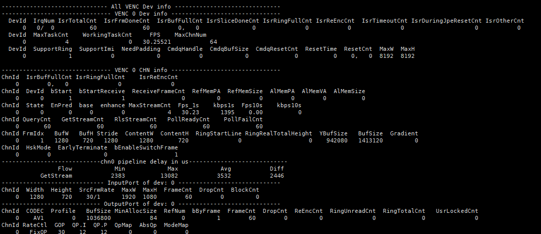
-
Debug info analysis
Record the current usage status of a VENC device, as well as device attributes, layer attributes, and inputport attributes, which can be dynamically obtained for debugging and testing.
-
Parameter Description
Parameter Description Dev info DevId Device number, refer to Table 5-1 IrqNum Interrupt number IsrTotalCnt Total number of various types of interrupt IsrFrmDoneCnt Total number of interrupt of frame done type IsrBufFullCnt The total number of interrupt of buffer full type IsrSliceDoneCnt Total number of interrupt of slice done IsrRingFullCnt The total number of interrupt of ring buffer full type IsrReEncCnt The total number of interrupt of re-encoding type IsrTimeoutCnt The total number of interrupt timed out IsrDuringJpeResetCnt isr count during JPEG reset IsrOtherCnt The total number of other types of interrupt MaxTaskCnt Support the maximum number of tasks that can be processed at the same time WorkingTaskCnt Number of tasks being processed FPS Statistics the output frame rate of the device MaxChnNum The maximum channel num SupportRing Whether to support HW RING SupportImi Whether to support HW REALTIME NeedPadding Need MI SYS clear padding or not CmdqHandle cmdq handle value CmdqBufSize cmdq buffer size CmdqResetCnt cmdq reset count ResetTime The time taken for the last Big Reset to occur on the device ResetCnt Device Big Reset count MaxW The width of max resolution MaxH The height of max resolution CHN info ChnId Channel ID bStart Whether channel encoding has been started bStartReceive Whether the channel has started receiving image data ReceiveFrameCnt The number of frames received by the last call to the start interface. If the value is 0, it means that the image coding is received until the user stops receiving the image coding RefMemPA The hardware physical address required by the underlying driver RefMemSize The hardware memory size required by the underlying driver AlMemPA The CPU physical address required by underlying driver AlMemVA The CPU virtual address required by underlying driver AlMemSize The CPU memory size required by underlying driver State Underlying processing state: typedef enum
{
E_MI_VENC_BUFSTATE_IDLE = 0,
E_MI_VENC_BUFSTATE_ENCODE,
E_MI_VENC_BUFSTATE_DONEWAIT_CMDQ,
E_MI_VENC_BUFSTATE_CHECK,
E_MI_VENC_BUFSTATE_DROP,
E_MI_VENC_BUFSTATE_DROP_FORCEBUF_OVERRIDE,
E_MI_VENC_BUFSTATE_RECOVER,
E_MI_VENC_BUFSTATE_BUF_FULL,
E_MI_VENC_BUFSTATE_MAX
} MI_VENC_BufferState_e;EnPred Whether the frame of the base layer is used as a reference by other frames of the base layer base Period of the base layer, value range: (0, +∞) enhance Period of the enhance layer, value range: [0, 255] MaxStreamCnt Maximum output buffer number Fps_1s Count the output frame rate within 1s kbps1s Count the output bit rate within 1s Fps10s Count the output frame rate within 10s kbps10s Statistic output bit rate within 10s QueryCnt The number of times that APP calls MI_VENC_Query GetStreamCnt The number of times that APP calls MI_VENC_GetStream RlsStreamCnt The number of times that APP calls MI_VENC_ReleaseStream PollReadyCnt The number of successful APP calls to select/poll PollFailCnt Number of failed select/poll calls by APP FrmIdx The serial number of the current frame: Before Pudding, the value is: 1, 2, 3, 4 After Pudding, the value is: 1, 2, 4 BufW The width of input yuv buffer BufH The height of input yuv buffer Stride The stride of input yuv buffer ContentW The effective width of input yuv buffer ContentH The effective height of input yuv buffer RingStartLine ring start line in ring mode RingRealTotalHeight ring real total height in ring mode YBufSize Y buffer size BufSize YUV total buffer size Gradient The gradient value passed by the front-end isp HskMode handshark mode
1: Enable the backstop
0: Disable the backstopEarlyTerminate Early Terminate state
1: Early Terminate is enabled.
0: Early Terminate is turned off.bEnableSwitchFrame bEnableSwitchFrame state
1: Enable AV1 s-frame encoding.
0: Disable AV1 s-frame encoding.chn pipeline delay in us Flow GetStream by app Min The minimum delay from the Buffer generation to the flow corresponding to the chn Max The maximum delay from the Buffer generation to the flow corresponding to the chn Avg The average delay between the Buffer generation and the corresponding Flow of the chn Diff The current delay from the Buffer generation to the flow corresponding to the chn Inputport info ChnId Channel ID Width Picture width (pixels) Height Picture height (pixels) SrcFrmRate Source frames per second, usually used as a parameter of rate control MaxW Maximum picture width (pixels) MaxH Maximum picture height (pixels) FrameCnt Count of frames processed DropCnt Count of dropped frames BlockCnt The total number of input pictures that have been received but rewinded because the previous input picture is still being processed. Assuming that it can process up to two input pictures at the same time, if the two input pictures have not been encoded and executed, the third frame comes, then the third frame will be rewinded, BlockCnt++. Outputport info ChnId Channel ID CODEC Which CODEC to use: H264,H265,JPEG,AV1 Profile Profile value BufSize Output pool total size (bytes) set by user MinAllocSize Minimum output buffer size allowed to be allocated RefNum Maximum number of reference frames bByFrame Does the subsequent stage take one frame at a time? 0: No, usually means to fetch data according to slice 1: Yes FrameCnt Count of frames that have been encoded and released DropCnt Count of frames that have been encoded but dropped ReEncCnt Count of re-encoded frames RingUnreadCnt Count of frames in the output pool that have not yet been taken RingTotalCnt Count of frames in the output pool UsrLockedCnt Count of frames the user is holding RateCtl Rate Control algorithm: CBR/VBR/AVBR/FixQP, etc. GOP Group of Picture, I frame interval QP.I QP of I-Frame, all macroblock Qp values of I frame in H264/H265/AV1 FixQP QP.P QP of P-Frame, all macroblock Qp values of P frame in H264/H265/AV1 FixQP MaxBitrate In CBR/VBR/AVBR, the maximum target bit rate (bits per second) IPQPDelta The Delta between the average QP value and the QP of the current I frame MaxQp In CBR/VBR/AVBR, the maximum allowed QP MinQp In CBR/VBR/AVBR, the minimum allowed QP MaxIQP In CBR/VBR/AVBR, the maximum allowed I frame QP MinIQP In CBR/VBR/AVBR, the minimum allowed I frame QP u32MaxIPProp In CBR/VBR/AVBR, the maximum ratio of I/P frame size MaxISize Maximum size of I frame MaxPSize Maximum size of P frame ChangePos The ratio of the bit rate when VBR/AVBR starts to adjust QP to the maximum bit rate MinStPct In AVBR, the minimum percentage of the target bit rate in the static state MaxStillQp In AVBR, the maximum I frame QP in static state MotionSens In AVBR, adjust the sensitivity of the bit rate according to the degree of motion of the screen QpMap The QPMAP mode allows users to freely determine the rate control strategy AbsQp Use absolute QP value ModeMap 0 decided byhw; 1 force skip; 2 force intra Qfactor Under PEG FixQP, the quantization factor MaxQfactor Under JPEG CBR, the maximum quantization factor MinQfactor Under JPEG CBR, the minimum quantization factor UbrMode Under H26x UBR, encode mode:
0: default mode
1: FrameQp, disable bitrate
2: fixed block QpFrameQp Under H26x UBR, set current encoding frame Qp TargetBits Under H26x UBR, set current encoding frame target bitrate bDropCurrentFrame Under H26x UBR, whether drop current frame bForceSkip Under H26x UBR, whether encode skip frame
5.2. echo
| Function | Dump input buffer |
|---|---|
| Command | echo dump_in [ChnId] [num] [dump_path] > /proc/mi_modules/mi_venc/mi_venc[DevID] |
| Parameter Description | [ChnId]: Channel ID [num]: The total number of sheets that need dump_in [dump_path]: Path to save the file [DevID]: Device ID, refer to Table 5-1 |
| Example | echo dump_in 0 10 /mnt > /proc/mi_modules/mi_venc/mi_venc0 |
| Function | Dump output stream |
|---|---|
| Command | echo dump_out [ChnId] [num] [dump_path] > /proc/mi_modules/mi_venc/mi_venc[DevID] |
| Parameter Description | [ChnId]: Channel ID [num]: The total number of sheets that need dump_out [dump_path]: Path to save the file [DevID]: Device ID, refer to Table 5-1 |
| Example | echo dump_out 0 100 /mnt > /proc/mi_modules/mi_venc/mi_venc0 |
| Function | Drop/Release the corresponding channel output task |
|---|---|
| Command | echo drop_out [ChnId] [Status] > /proc/mi_modules/mi_venc/mi_venc[DevID] |
| Parameter Description | [ChnId]: Channel ID, a means all channels [Status]: r : release the corresponding channel output task d : drop the corresponding channel output task [DevID]: Device ID, refer to Table 5-1 |
| Example | echo drop_out 0 d > /proc/mi_modules/mi_venc/mi_venc0 // drop channel 0 output task echo drop_out 0 r > /proc/mi_modules/mi_venc/mi_venc0 // release channel 0 output task echo drop_out a d > /proc/mi_modules/mi_venc/mi_venc0 // drop the whole channel output task echo drop_out a r > /proc/mi_modules/mi_venc/mi_venc0 // release the whole channel output task |
| Function | Drop/Release the corresponding channel input task |
|---|---|
| Command | echo drop_in [ChnId] [Status] > /proc/mi_modules/mi_venc/mi_venc[DevID] |
| Parameter Description | [ChnId]: Channel ID, a means all channels [Status]: r : release the corresponding channel input task d : drop the corresponding channel input task [DevID]: Device ID, refer to Table 5-1 |
| Example | echo drop_in 0 d > /proc/mi_modules/mi_venc/mi_venc0 // drop channel 0 input task echo drop_in 0 r > /proc/mi_modules/mi_venc/mi_venc0 // release channel 0 input task echo drop_in a d > /proc/mi_modules/mi_venc/mi_venc0 // drop the whole channel input task echo drop_in a r > /proc/mi_modules/mi_venc/mi_venc0 // release the whole channel input task |
| Function | Dump dump customer qp map |
|---|---|
| Command | echo dump_map [ChnId] [dump_times] [dump_path] > /proc/mi_modules/mi_venc/mi_venc0 |
| Parameter Description | [ChnId]: Channel ID [dump_times]: Dump times [dump_path]: Path to save the file [DevID]: Device ID, refer to Table 5-1 |
| Example | echo dump_map 0 1 /mnt > /proc/mi_modules/mi_venc/mi_venc0 |
| Function | Reload the modparam parameters |
|---|---|
| Command | echo load_modparam > /proc/mi_modules/mi_venc/mi_venc[DevID] |
| Parameter Description | [DevID]: Device ID, refer to Table 5-1 |
| Example | echo load_modparam > /proc/mi_modules/mi_venc/mi_venc0 |
6. MODPARAM.json Description
-
The VENC allows some parameter configurations to be modified through modparam where necessary. The following table describes the parameters:
Parameter
Function
Default Parameter
Maruko Opera Souffle Iford use_ring_ref Whether to enable frame saving mode. Do not support super frame recoding when enabled. 1 1 1 1 max_chn_num Maximum number of channels that can be created on a device 64 64 64 64 s32PreloadChnFlag Under DualOs, the switch for pre caching the bitstream in H264/5, with each encoding channel number corresponding to a Bit set to 1 as enabled 0 0 0 0 u32Chn0PreloadBufSize Under DualOs, the output cache size corresponding to channel 0 after H264/5 enables pre caching of the bitstream. When not set or set to 0, it will be dynamically calculated internally based on the bitrate parameters and pre cached frame rates 0 0 0 0 u32Chn1PreloadBufSize Under DualOs, the output cache size corresponding to channel 1 after H264/5 enables pre caching of the bitstream. When not set or set to 0, it will be dynamically calculated internally based on the bitrate parameters and pre cached frame rates 0 0 0 0 u32Chn2PreloadBufSize Under DualOs, the output cache size corresponding to channel 2 after H264/5 enables pre caching of the bitstream. When not set or set to 0, it will be dynamically calculated internally based on the bitrate parameters and pre cached frame rates 0 0 0 0 s32JpePreloadChnFlag Under DualOs, the switch for pre caching the bitstream in JPEG, with each encoding channel number corresponding to a Bit set to 1 as enabled 0 0 0 0 u32JpeChn0PreloadBufSize Under DualOs, the output cache size corresponding to channel 0 after JPEG enables pre caching of the bitstream. When not set or set to 0, it will be dynamically calculated internally based on the bitrate parameters and pre cached frame rates 0 0 0 0 u32JpeChn1PreloadBufSize Under DualOs, the output cache size corresponding to channel 1 after JPEG enables pre caching of the bitstream. When not set or set to 0, it will be dynamically calculated internally based on the bitrate parameters and pre cached frame rates 0 0 0 0 u32JpeChn2PreloadBufSize Under DualOs, the output cache size corresponding to channel 2 after JPEG enables pre caching of the bitstream. When not set or set to 0, it will be dynamically calculated internally based on the bitrate parameters and pre cached frame rates 0 0 0 0 ven_clock H264/5 hardware clock. If not set or set to 0, the default value will be used internally 0 0 0 0 ven_clock_2nd H264/5 hardware sub-module clock. If not set or set to 0, the default value will be used internally 0 0 0 0 jpe_clock JPEG hardware clock. If not set or set to 0, the default value will be used internally 0 0 0 0 VenMiuPChn The total number of channels for H264/5 encoding channel data protection, which is set according to the actual maximum number of channels that need to be encoded. If not set or set to 0, the default value will be used internally 0 0 0 0 -
Module parameters can be configured and modified using modparam.json file, which is usually under the /config path in the board. Set the parameters in the following way:
"E_MI_MODULE_ID_VENC" : { "use_ring_ref" : 0, "max_chn_num" : 8, } -
Note
- Parameter initialization is completed during insmod ko.