Sigmastar eMMC Debug SOP Manual
REVISION HISTORY
| Revision No. | Description |
Date |
|---|---|---|
| 1.0 | 02/21/2024 |
1. eMMC Device Not Recognized
| Flow | Method | Exit Condition | Next Step | Information Required by SWRD | Related FAQ References |
|---|---|---|---|---|---|
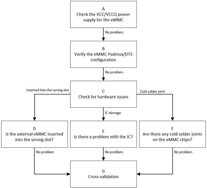
| A | 1. Use multimeter to confirm whether eMMC VCC voltage is 3.3V during initialization phase 2. Confirm that CLK line is at low level by default, while CMD/DATA lines are at high level 3. Confirm whether eMMC VCCQ voltage is within 1.8V/3.3V range |
Exit Condition 1: 1. eMMC VCC supply during initialization deviates significantly from 3.3V, 2. Or default state of bus line is incorrect, 3. Or eMMC VCCQ supply is not within valid 1.8V/3.3V range ==> Power supply issue Exit Condition 2: Power supply normal ==> No issue |
Exit Condition 1: > Flow ends Exit Condition 2: > B |
Exit Condition 1: ==> Seek CAE assistance |
|
| B | 1. Confirm whether eMMC padmux configuration matches the development board, and whether pad conflicts with other modes. Method: cd vim arch/arm/boot/dts/iford_xxxx-padmux.dtsi eMMC padmux mode will contain 'EMMC4B_MODE' or 'PM_SDIO_MODE' keywords, corresponding GPIO pads should be checked for conflicts with other modules 2. Confirm whether eMMC DTS configuration matches the currently used slot. Method: cd vim arch/arm/boot/dts/iford.dtsi For configuration item meanings, refer to 2.1 no-sdio/no-sd/no-mmc, comment out the corresponding item based on device type, and configure the other two. For example: when connecting eMMC card, comment out no-mmc, and configure no-sdio/no-sd 2.2 reg/cifd-reg/pwr-save-reg, these are bank addresses corresponding to the IP used, divided into non-pm and pm, with non-pm base at 0x1F282600 and pm base at 0x1F008400 2.3 ip-order/interrupts/clocks, ensure one-to-one correspondence. For example, if using ip-order=0, the interrupts and clocks corresponding slot options must match the current slot. Configure non-pm ip-order as 0, pm ip-order as 1 |
Exit Condition 1: 1. padmux not correctly configured or conflicts with other modes 2. eMMC related configuration items in DTS do not match the currently used slot ==> Configuration error Exit Condition 2: Configuration normal ==> No issue |
Exit Condition 1: > Flow ends Exit Condition 2: > C |
Exit Condition 1: ==> Seek CAE to confirm current board padmux usage, then configure correct padmux and DTS according to actual situation |
|
| C | 1. Confirm whether hardware issues exist 1.1 Scenario 1 - Wrong slot: When board uses external eMMC with multiple slots, connect according to actual situation 1.2 Scenario 2 - IC pin output unstable: Use multimeter or oscilloscope to measure signals near IC side and Device side, unstable signal phenomenon should not occur 1.3 Scenario 3 - eMMC chip poor soldering: When eMMC is built-in on board and other conditions are ruled out, consider re-soldering the eMMC chip |
Exit Condition 1: 1. Confirmed external eMMC placed in wrong slot > Insert into correct slot Exit Condition 2: IC pin output unstable, causing poor signal quality > Replace with new IC Exit Condition 3: eMMC chip poor soldering, causing poor signal quality > Re-solder eMMC Exit Condition 4: Hardware normal > No issue |
Exit Condition 1: > Flow ends Exit Condition 2: > Flow ends Exit Condition 3: > Flow ends Exit Condition 4: > G |
Exit Condition 2: > Seek CAE assistance Exit Condition 3: > Seek CAE assistance |
|
| G | 1. Replace with same specification eMMC and test again for normal recognition 2. Replace development board and test same specification eMMC for normal recognition 3. Test same specification eMMC on other platforms for normal recognition |
Exit Condition 1: After replacing with same specification eMMC, recognition becomes normal > eMMC device issue Exit Condition 2: After replacing development board, recognition becomes normal > Development board issue Exit Condition 3: After testing on other platforms, recognition becomes normal ==> Driver issue exists |
Exit Condition 1: > Flow ends Exit Condition 2: > Flow ends Exit Condition 3: ==> Flow ends |
Exit Condition 3: > 1. Provide serial port log > 2. Use LA or oscilloscope to capture waveforms of entire initialization process ==> 3. Under Linux console, dump eMMC IP related bank information through riu command: non-pm:0x1413/0x1038/0x103C/0x1033 pm:0x42/0xE/0x3F |
2. eMMC Read/Write Failure Issue
| Flow | Method | Exit Condition | Next Step | Information Required by SWRD | Related FAQ References |
|---|---|---|---|---|---|
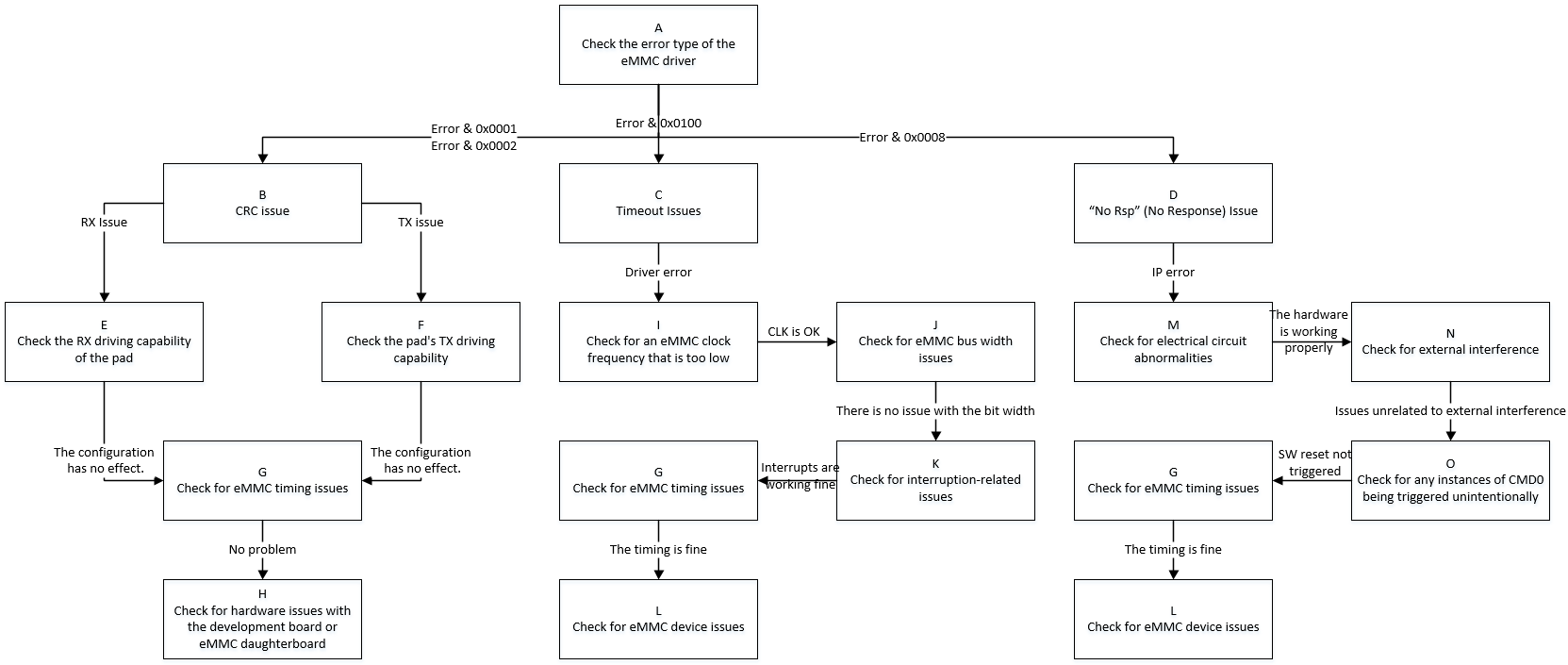
| A | When error occurs, search debug log using keyword "[sdmmc", mainly focus on error num: 1.(E: 0x0001): Read CRC 2.(E: 0x0002): Write CRC 3.(E: 0x0010): CMD CRC 3.(E: 0x0100): Driver reports Timeout 4.(E: 0x0008): IP reports Device No Rsp |
Exit Condition 1: 1. cmd 12/13/17/18/23/24/25 and other read/write related commands report CRC error during execution Exit Condition 2: 1. cmd 12/13/17/18/23/24/25 and other read/write related commands report Timeout error during execution Exit Condition 3: 1. cmd 12/13/17/18/23/24/25 and other read/write related commands report device no response error |
Exit Condition 1: > B Exit Condition 2: > C Exit Condition 3: ==> D |
||
| B | CRC issue is essentially poor signal quality, select optimal pad driving capability based on CRC error type | Exit Condition 1: 1. CRC error type is RX CRC, i.e., error during read Exit Condition 2: 1. CRC error type is TX CRC, i.e., error during write Exit Condition 3: 1. Other CRC error types |
Exit Condition 1: > E Exit Condition 2: > F Exit Condition 3: ==> G |
||
| C | 1. When driver reports timeout for read/write operations, capture waveforms immediately to confirm whether transmission performance issue exists 2. If waveforms show no issues, determine whether eMMC MIE interrupt is normally reported or received, refer to 3. Check whether eMMC Timing is abnormal, common Timing issues see 4. If above issues are ruled out, consider whether eMMC Device is abnormal |
Exit Condition 1: 1. Based on waveforms, current operating frequency is lower than expected Exit Condition 2: 1. Check bus width, does not match expectation Exit Condition 3: 1. Debug log shows related events did not trigger normally when error occurred Exit Condition 4: 1. eMMC Timing abnormal Exit Condition 5: 1. eMMC Device reason causes card busy situation |
Exit Condition 1: > I Exit Condition 2: > J Exit Condition 3: > K Exit Condition 4: > G Exit Condition 5: ==> L |
||
| D | 1. When eMMC IP reports Device no response, capture waveforms to confirm whether no response received after CMD issued 2. Refer to <1: eMMC Device Not Recognized>, check whether related configuration is correct 3. Priority check whether hardware electrical path is normal, test operating environment with interference (e.g., ESD, high/low temperature) 4. Search Debug log for "SAR1 SDMMC WARN trigger" keyword to determine whether power-off protection is mistakenly triggered 5. Check whether eMMC Timing is abnormal 6. If above issues are ruled out, consider whether eMMC Device is abnormal |
Exit Condition 1: 1. Check configuration no issue, waveform shows no Device response received after CMD issued Exit Condition 2: 1. Electrical path between CHIP and eMMC daughterboard shows significant signal attenuation Exit Condition 3: 1. Operating environment currently undergoing ESD or high/low temperature stress testing Exit Condition 4: 1. Search log, discover eMMC power-off protection triggered while power not disconnected Exit Condition 5: 1. eMMC Timing abnormal Exit Condition 6: 1. eMMC Device reason causes no response Exit Condition 7: 1. Waveform shows Device response, but IP determines no response |
Exit Condition 1: > Flow ends Exit Condition 2: 1. Request CAE assistance for troubleshooting Exit Condition 3: > Flow ends Exit Condition 4: > Flow ends Exit Condition 5: > G Exit Condition 6: > L Exit Condition 7: > Flow ends |
Exit Condition 1: 1. Dump debug log and DTS configuration file Exit Condition 3: Exit Condition 4: 1. Dump debug log Exit Condition 7: 1. Suspect CHIP design defect |
|
| E | Refer to 《eMMC User Guide》 | Exit Condition 1: 1. After setting data driving gear according to actual situation, returns to normal Exit Condition 2: 1. After trying all data driving gears, CRC error still occurs |
Exit Condition 1: > Flow ends Exit Condition 2: > G |
||
| F | Refer to 《eMMC User Guide》 | Same as "E" | Same as "E" | ||
| G | 1. Refer to 《eMMC User Guide》 to comprehensively adjust CLK/CMD line driving capability 2. Adjust CLK phase, specific operation refer to 《eMMC User Guide》 3. Adjust clock signal sampling mode according to TMUX table and eMMC REG table 4. When trans-mode uses DMA, need to set reg_dma_rd_clk_stop to avoid data loss 5. Use LA or oscilloscope to capture complete waveforms during problem occurrence |
Exit Condition 1: 1. After comprehensively adjusting signal line driving gear, returns to normal Exit Condition 2: 1. After adjusting CLK 4-phase or 8-phase, returns to normal Exit Condition 3: 1. After adjusting clock signal sampling mode, returns to normal Exit Condition 4: 1. In DMA Mode transmission scenario, after setting offset:0xb bit7, returns to normal Exit Condition 5: 1. Above measures ineffective, waveform differs from normal scenario, such as rising edge sampling lock time not meeting standards, cmd overlap, cmd minimum interval not meeting standards, etc. Exit Condition 6: 1. Confirmed above settings normal, waveform no abnormality |
Exit Condition 1: Exit Condition 2: Exit Condition 3: Exit Condition 4: > Flow ends Exit Condition 5: > Flow ends Exit Condition 6: ==> H/L |
Exit Condition 5: 1. Dump complete debug log of entire process, including from eMMC init to problem occurrence 2. Capture complete waveforms of abnormal scenario, preferably with normal scenario waveforms under same conditions for comparison 3. Under Linux console, dump eMMC IP related bank information through riu command: non-pm:0x1413/0x1038/0x103C/0x1033 pm:0x42/0xE/0x3F |
|
| H | 1. For external eMMC scenario, first refer to <1: eMMC Device Not Recognized> cross-validation chapter 2. In Default state (i.e., no data interaction), use multimeter or oscilloscope to measure eMMC CLK/CMD/DATA Line electrical signals to confirm whether they meet expectations 3. During communication trigger (i.e., data interaction), use multimeter or oscilloscope to measure electrical signals near chip side and near Device side respectively to confirm whether significant signal difference exists 4. Through means such as adding pull-up resistors, attempt to enhance driving capability from hardware perspective |
Exit Condition 1: 1. After cross-validation, communication returns to normal Exit Condition 2: 1. In default condition, CLK line not at low level, CMD/DATA lines not at high level Exit Condition 3: 1. Electrical signals show attenuation and other anomalies between IC side and Device side Exit Condition 4: 1. After hardware adjustment to improve signal quality, communication returns to normal Exit Condition 5: 1. Electrical signals normal, hardware adjustment ineffective |
Exit Condition 1: > Flow ends Exit Condition 2: 1. Check whether padmux configuration matches current eMMC slot 2. Under Linux, use LA or oscilloscope to manually pull up/down eMMC pin GPIO to verify expectations Exit Condition 3: Exit Condition 4: Exit Condition 5: > Flow ends |
Exit Condition 3: 1. Seek CAE assistance Exit Condition 5: 1. Synchronize hardware conditions, help RD set up reproduction environment |
|
| I | 1. According to manual, confirm the version of eMMC IP used by current slot 1.1 eMMC4.3 supports up to 48MHz 1.2 eMMC5.0 HS200/HS400 supports up to 200MHz 2. Within IP allowed frequency range, confirm whether already at highest gear 3. Read bank 0x1038 offset 0x43/bank 0x42 offset 0x24 to confirm whether CLK is set as expected |
Exit Condition 1: 1. After adjusting CLK to highest gear, communication returns to normal Exit Condition 2: 1. Adjusting CLK has no effect or already at highest gear Exit Condition 3: 1. CLK setting does not match register read value |
Exit Condition 1: > Flow ends Exit Condition 2: > J Exit Condition 3: ==> Flow ends |
Exit Condition 3: 1. non-pm dump 0x1038/0x1133 register information pm dump 0xe register information 2. Provide DTS configuration file 3. Provide Debug Log |
|
| J | 1. According to SPEC document, different speed modes have corresponding supported bus widths 1.1 eMMC4.3 can use 1bit/4bit/8bit Buswidth 1.2 eMMC5.0 HS200 can use 4bit/8bit width 1.3 eMMC5.0 HS400 only supports 8bit width 2. Read bank 0x1413/0x42 offset 0xb[2:1] to confirm |
Exit Condition 1: 1. After adjusting Buswidth to maximum width for corresponding speed mode, communication returns to normal Exit Condition 2: 1. Adjusting Buswidth has no effect or already at maximum width for current speed mode Exit Condition 3: 1. Buswidth setting does not match register read value |
Exit Condition 1: > Flow ends Exit Condition 2: > K Exit Condition 3: ==> Flow ends |
Exit Condition 3: 1. Dump 0x1413/0x42 register information 2. Provide DTS configuration file 3. Provide Debug Log |
|
| K | 1. Read bank 0x1413 offset 0x0[1:0] to determine whether read/write completion event is raised 2. If event has been triggered but driver still reports timeout, priority check CPU Loading and interrupt trigger count |
Exit Condition 1: 1. Within driver timeout period, event not raised Exit Condition 2: 1. Event has been raised, and CPU Loading is high or interrupts triggered frequently Exit Condition 3: 1. Event raised normally, environment has no other anomalies |
Exit Condition 1: > Flow ends Exit Condition 2: Identify which process causes high CPU Loading, try binding eMMC MIE interrupt handler to CPU1 Exit Condition 3: > G |
Exit Condition 1: 1. Try reproducing on reference board, help RD set up environment |
|
| L | 1. First confirm whether eMMC end-of-life has been reached: cd /sys/kernel/debug/mmc/mmc:xxxx cat ext_csd Where bits 537~538 indicate life time, see SPEC for details 2. Refer to <1: eMMC Device Not Recognized> cross-validation chapter 3. Re-solder eMMC chip |
Exit Condition 1: 1. eMMC life time has exceeded maximum or approaching maximum Exit Condition 2: 1. After cross-validation or re-soldering, communication returns to normal Exit Condition 3: 1. Confirmed eMMC device normal |
Exit Condition 1: > Replace eMMC Exit Condition 2: > Flow ends Exit Condition 3: ==> Flow ends |
Exit Condition 3: 1. Try reproducing on reference board, help RD set up environment |
|
| M | 1. Use multimeter or oscilloscope to measure entire path from CHIP to eMMC daughterboard, mainly observe whether signals near CHIP side and eMMC daughterboard side show significant difference | Exit Condition 1: 1. Significant signal attenuation observed between near CHIP side and eMMC daughterboard side Exit Condition 2: 1. Electrical path normal |
Exit Condition 1: 1. Request CAE assistance for troubleshooting Exit Condition 2: ==> N |
||
| N | 1. Confirm with customer whether operating environment has external interference, such as undergoing ESD, high/low temperature stress testing | Exit Condition 1: 1. Undergoing stress testing with ESD, high/low temperature etc. Exit Condition 2: 1. No external interference, normal operating environment |
Exit Condition 1: > Flow ends Exit Condition 2: > O |
Exit Condition 1: 1. Capture Debug log and waveforms 2. Coordinate with CAE for joint troubleshooting |
|
| O | 1. Under confirmed non-power-off operating environment, check whether Debug log contains "SAR1 SDMMC WARN trigger" keyword 2. Check whether filter contains "retry", "reset" keywords related to eMMC driver |
Exit Condition 1: 1. Check Debug log, eMMC triggering power-off protection or retry operation exists Exit Condition 2: 1. Environment not reset or eMMC power-off protection mistakenly triggered |
Exit Condition 1: > Flow ends Exit Condition 2: > G |
Exit Condition 1: 1. eMMC mistakenly triggering power-off protection 2. If environment has reset operation triggered, capture Debug log |
3. eMMC Read/Write Success but Data in Buffer Abnormal
| Flow | Method | Exit Condition | Next Step | Information Required by FAE | Related FAQ References |
|---|---|---|---|---|---|
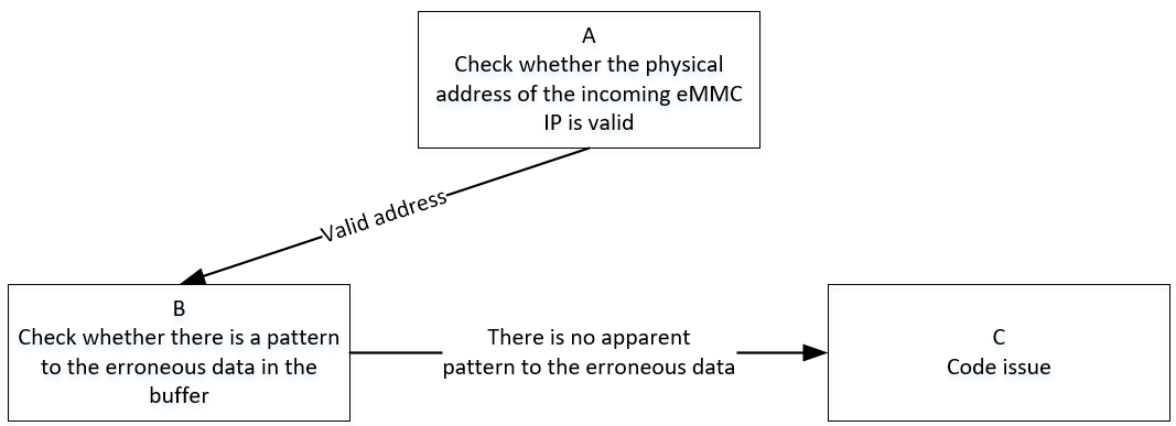
| A | 1. Refer to specification document to confirm eMMC IP usable DRAM address space, then confirm whether physical address offset passed to eMMC IP is valid, i.e., address composed of bank 1413/42 offset 0x3/0x4. 2. Linux usable address space starts from 0x20000000, eMMC IP uses physical address with 0x20000000 address offset subtracted, i.e., offset 0x3/0x4 is filled physical address, starting from 0 to maximum usable offset, this offset needs to be confirmed with FAE |
Exit Condition 1: 1. Physical address offset passed to eMMC IP exceeds valid range Exit Condition 2: 1. Physical address offset passed to eMMC IP is valid |
Exit Condition 1: > Flow ends Exit Condition 2: > B |
Exit Condition 1: 1. Use system-provided standard address space allocation interface to apply for buf |
|
| B | 1. Construct test pattern, confirm whether difference between source pattern and read/write pattern shows regularity, use fio tool to specify pattern | Exit Condition 1: 1. Pattern error obviously shows regularity, always error with eMMC driver Cache-line size Exit Condition 2: 1. Pattern error shows no obvious regularity |
Exit Condition 1: > Flow ends Exit Condition 2: > C |
Exit Condition 1: 1. Confirm whether using eMMC standard read/write interface, if not, further confirm whether buf is non-cache 2. Provide reference board reproduction environment |
|
| C | eMMC driver read/write process normal, abnormal occurs during IP internal data transfer, mainly consider following points: 1. Whether dma burst length is set to 8, i.e., bank 1413/42 offset 0x2[5:4] 2. Whether Cache operations considered or handled incorrectly during read/write 3. Data synchronization issues caused by modern CPU out-of-order execution |
Exit Condition 1: 1. dma burst length not set to maximum Exit Condition 2: 1. In Cache-on operating environment, invalid and flush operations not performed during buf read/write, causing inconsistent data retrieval Exit Condition 3: 1. For logic requiring synchronous calls, memory barrier not applied, causing out-of-order execution Exit Condition 4: 1. Other issues |
Exit Condition 1: 1. Try manually setting dma burst to maximum value 8 Exit Condition 2: 1. Try executing flush operation during write, and invalid operation after read Exit Condition 3: Exit Condition 4: ==> Flow ends |
Exit Condition 3: Exit Condition 4: 1. Confirm customer branch and patch status 2. Provide reference board reproduction environment |
4. eMMC Boot Issue
| Flow | Method | Exit Condition | Next Step | Information Required by SWRD | Related FAQ References |
|---|---|---|---|---|---|
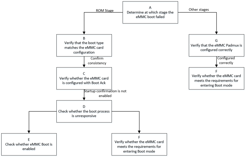
| A | First search Debug Log to determine which stage eMMC Boot fails at 1. If fails during ROM stage, Log will not show IPL and subsequent stage keywords 2. If fails after ROM stage, determine which stage of IPL/IPL_CUST/UBOOT based on last appearing keyword, then analyze problem specifically |
Exit Condition 1: 1. eMMC Boot fails during ROM stage Exit Condition 2: 1. eMMC Boot fails during stage after ROM |
Exit Condition 1: > B Exit Condition 2: > G |
||
| B | If fails during ROM boot stage, first check whether boot strap on board matches selection during isptool burning, current latest isptool can automatically match, for old version tools, need to ensure 'Bus Width' in option board matches board boot strap selection | Exit Condition 1: 1. Bus width selected during isptool burning does not match boot strap selected type Exit Condition 2: 1. Both configurations match |
Exit Condition 1: Correct Bus width during isptool burning Exit Condition 2: ==> C |
||
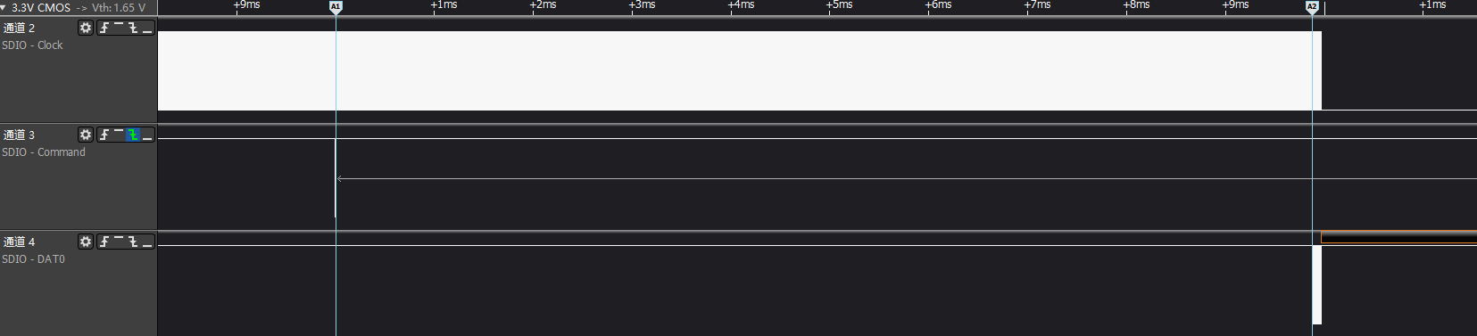
| C | refer to SPEC,Boot Ack mechanism will reply with Ack information on Dat0 line within maximum 50ms after cmd0 issued, capture waveforms to confirm whether Boot Ack mechanism is enabled or SPEC violation occurs, generally can be determined by first parameter of uboot burn command 'mmc partconf', 0 - disable Ack; 1 - enable Ack | Exit Condition 1: 1. Boot ACK mechanism enabled, and Ack information appears on other data line Exit Condition 2: 1. Boot Ack not configured as enabled |
Exit Condition 1: Disable Boot Ack mechanism, i.e., set ExtCSD[179] bit6 to 0 Exit Condition 2: ==> D |
||
| D | Capture eMMC Boot waveforms, confirm whether waveforms have response for Boot partition data | Exit Condition 1: 1. After cmd0 sent, no Boot partition data response, query ECSD[179] bit[5:3] shows card not enabled Boot mode Exit Condition 2: 1. After cmd0 sent, no Boot partition data response, and waveforms show not meeting Boot mode entry condition |
Exit Condition 1: > E Exit Condition 2: > F |
||
| E | Refer to Flow L of <2. eMMC Read/Write Failure Issue>, read ECSD[179] bit[5:3] register, and parse according to SPEC whether eMMC card has Boot mode enabled | Exit Condition 1: 1. eMMC card Boot mode not enabled Exit Condition 2: 1. eMMC card Boot mode enabled |
Exit Condition 1: 1. Use isptool to re-burn, and do not check disable part Exit Condition 2: ==> F |
||
| F | refer to SPEC,eMMC card Boot mode contains three states: 1. pre-idle state, three ways to enter: 1.1 after power on; 1.2 cmd0(arg:0xf0f0f0f0) command 1.3 hw reset by host 2. pre-boot state: after power on or reset and before sending first command cmd1, cmd line must maintain at least 74 clock cycles at low level 3. boot state: perform boot partition data read, mainly: 3.1 cmd line low level 3.2 cmd0(arg:0xfffffffa), current eMMC method |
Exit Condition 1: 1. Entering pre-idle state failed, i.e., current eMMC HW reset or cmd0(arg:0xf0f0f0f0) has no effect on eMMC card Exit Condition 2: 1. eMMC Timing issue exists |
Exit Condition 1: 1. Try switching HW reset/SW reset method to resolve Exit Condition 2: ==> Flow ends |
Exit Condition 2: 1. Capture eMMC Boot waveforms and Dump log 2. Assist RD to set up reproduction environment |
|
| G | Refer to Flow B of <1. eMMC Device Not Recognized>, check whether eMMC Padmux configuration is correct | Exit Condition 1: 1. eMMC Padmux configuration has issues Exit Condition 2: 1. eMMC Padmux configuration correct |
Exit Condition 1: 1. Configure correctly according to actual operating environment Exit Condition 2: ==> F |
5. Appendix
5.1 eMMC Device Initialization Flow

>>>eMMC go idle: cmd0 makes card enter idle state
Initialization will re-power on and off, device enters idle state
>>>Get OCR register information: Get card OCR information and wait for card ready
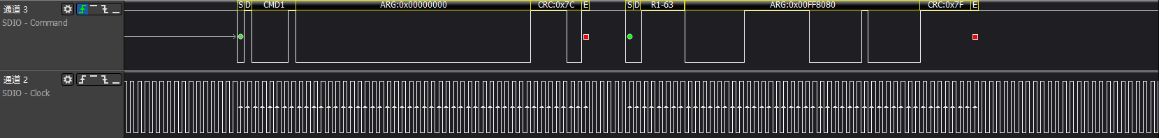
In idle state, host will get OCR register, and wait for card to complete power up routine finish, i.e.,
bit31 of cmd1 response set to 1 indicates card is ready
>>>sd go idle again: cmd0 makes card enter idle state
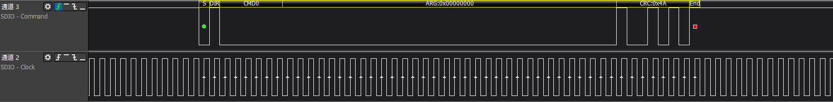
After getting OCR, host will perform reset action again
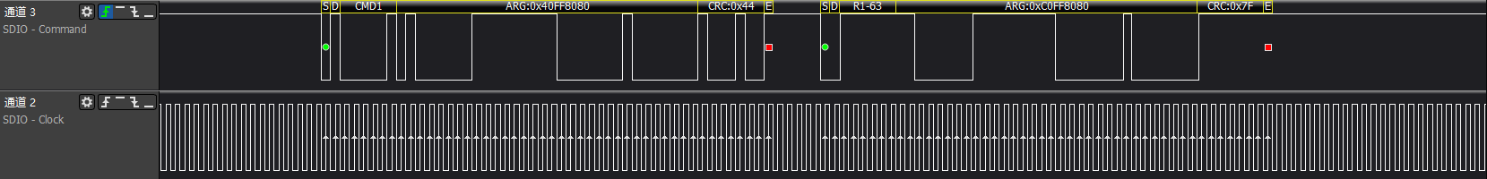
>>>cmd1: This time add host capabilities and re-get OCR
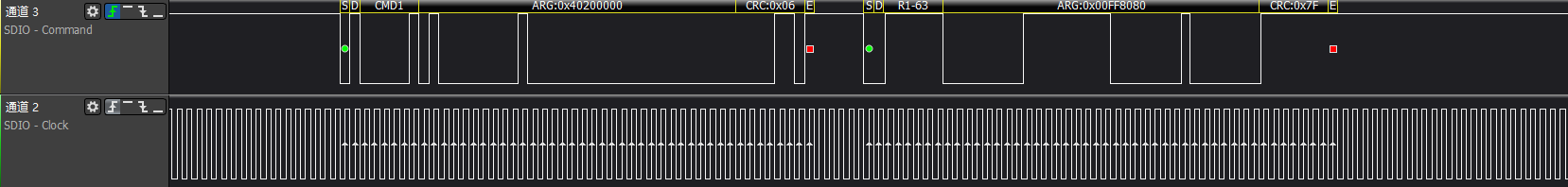
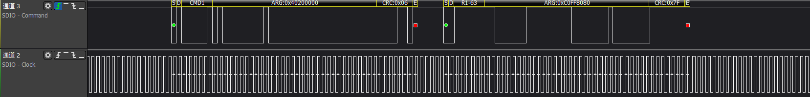
Host combines first OCR obtained, sends own capability set, because of re-power on and off, still need to wait for ready flag
>>>cmd3/cmd9/cmd7: host gets emmc card RCA address and gets CSD register information and card selection operation according to address
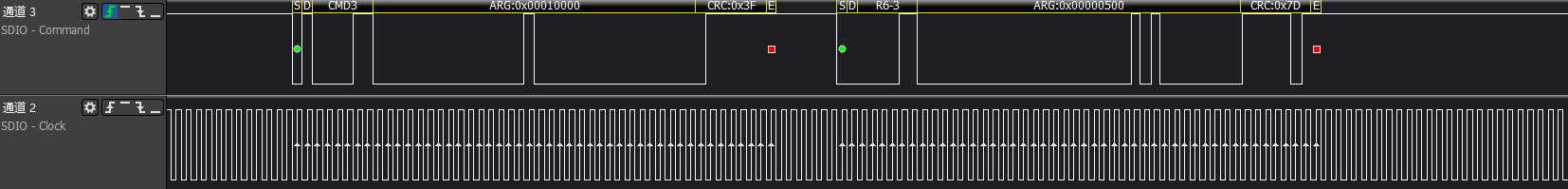
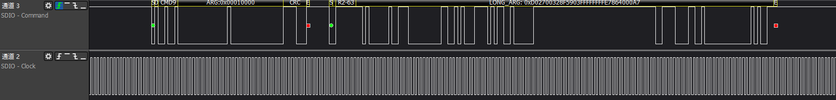
After selecting emmc card according to RCA, card will enter trans-state state
>>>Get EXT-CSD register information: emmc important extended register information
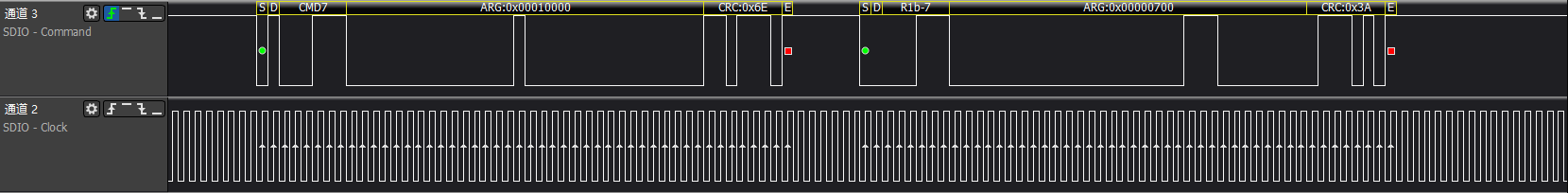
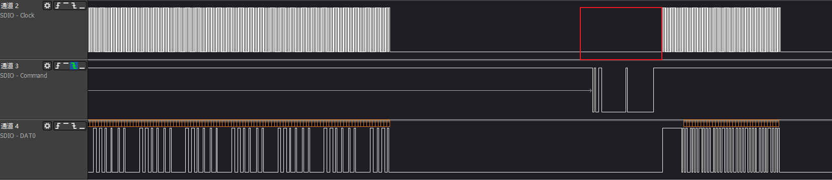
>>>cmd6+cmd13 switch operation: Perform series of settings and enable function operations
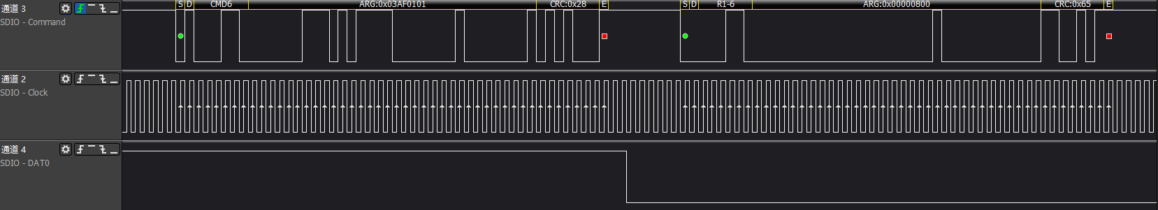
After reading ext-csd information, it's a series of cmd6+cmd13 paired switch operations, note that cmd6 rsp is r1b type, device status reflects in subsequent cmd13 rsp.
Sometimes also paired with assert busy signal (data0 pulled low) + r1 way to respond cmd6, as shown in above figure, switch operations mainly include:
1. enable erase group
2. ext-csd[179] boot partition enable
3. Switch to high-speed, after this step clock is 48MHz
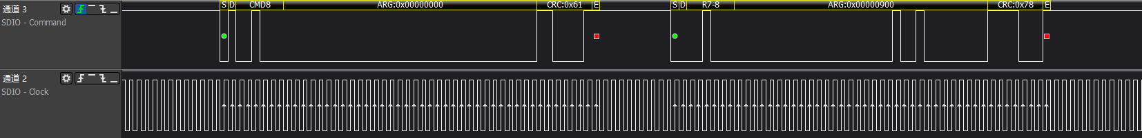
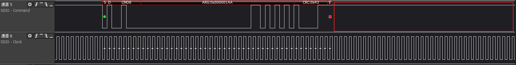
4. Switch bus width and send cmd8 to get confirmation
5. Select power class to confirm supply voltage
6. Switch cache ctrl to enable cache function
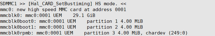
After above steps completed, because card device is generated, will match with card driver, generate block device node.
>>>emmc card recognition success
5.2 eMMC Common Error Waveforms and Logs
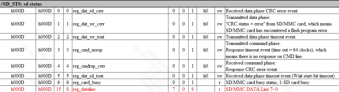
>>>reg_emmc status
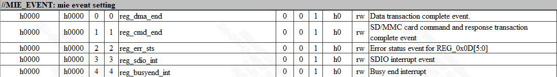
>>>reg_emmc event
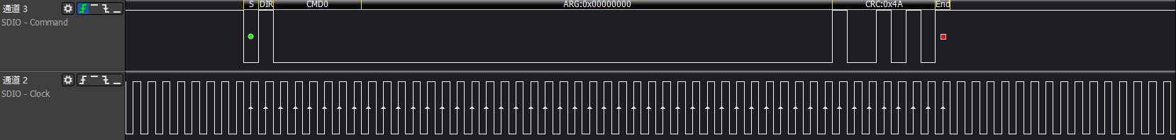
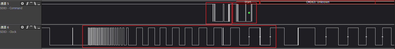
>>>cmd no rsp

Host has issued cmd request and clock normally outputs, but device response not received within 8T time
Driver will print SD_STS:0x0F08 error code, error code focuses on low 8 bits, refer to reg_sdio table offset:0xd for explanation
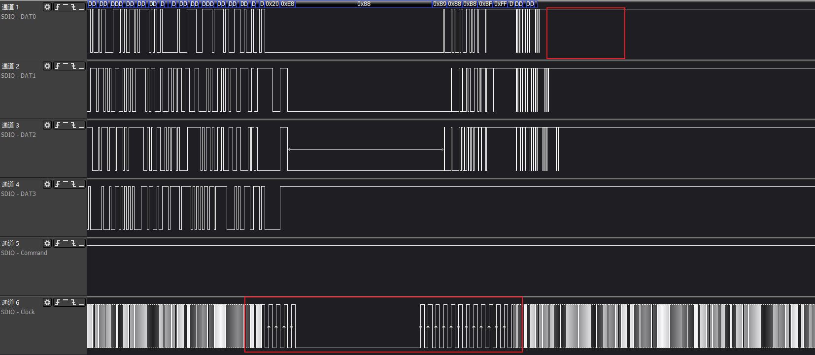
>>>cmd crc
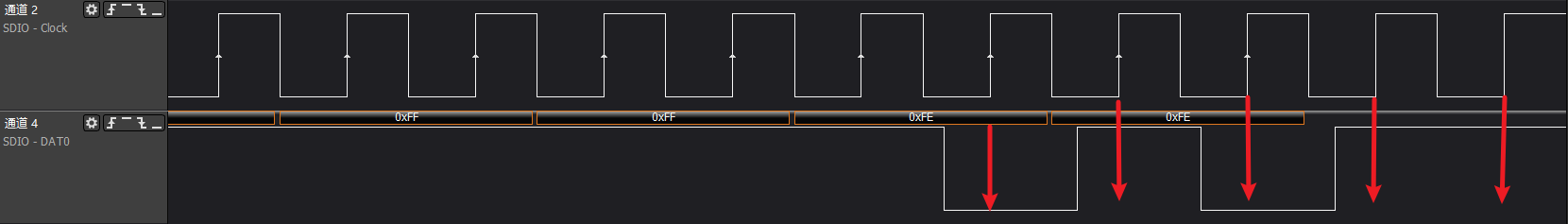


After host normally issues cmd17/18/24/25 write commands, data line has data response reply, last 5 bits of write command dat0 are device-identified CRC status confirmation. Correct is '00101', error is '01011'
Read command CRC is IP internal verification
Driver will print SD_STS:0x0F01 (read CRC) / SD_STS:0x0F02 (write CRC) error code, error code focuses on low 8 bits, refer to reg_sdio table offset:0xd for explanation
>>>cmd timeout
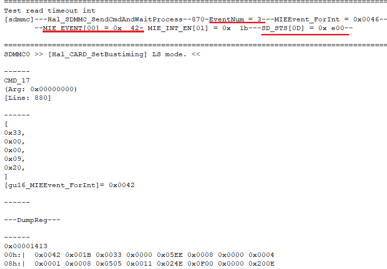
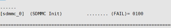
cmd timeout is driver-level judgment, so waveforms are generally normal, mainly reflected in driver debug err log
Driver will print (FAIL)= 0100 error code, indicating driver-set wait time has arrived, but event not received, refer to "2. eMMC Communication Process Issue"
Here can focus on key information prints pre-buried in driver, 'eventnum=3' indicates need to wait for read cmd with data, 'MIE_EVENT[00]=0x42' indicates only received cmd rsp, but dat_end event not received
Additionally can pay attention to 'SD_STS[0D]=0xe00' i.e., high 8 bits of sd status register, if not all 1s state, indicates data line has pull down situation, generally data still transferring or pulled down
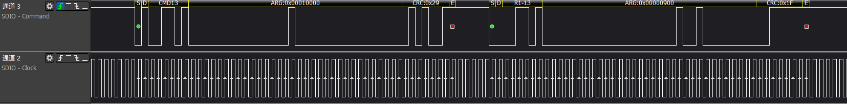
>>>cmd6 execute switch func error
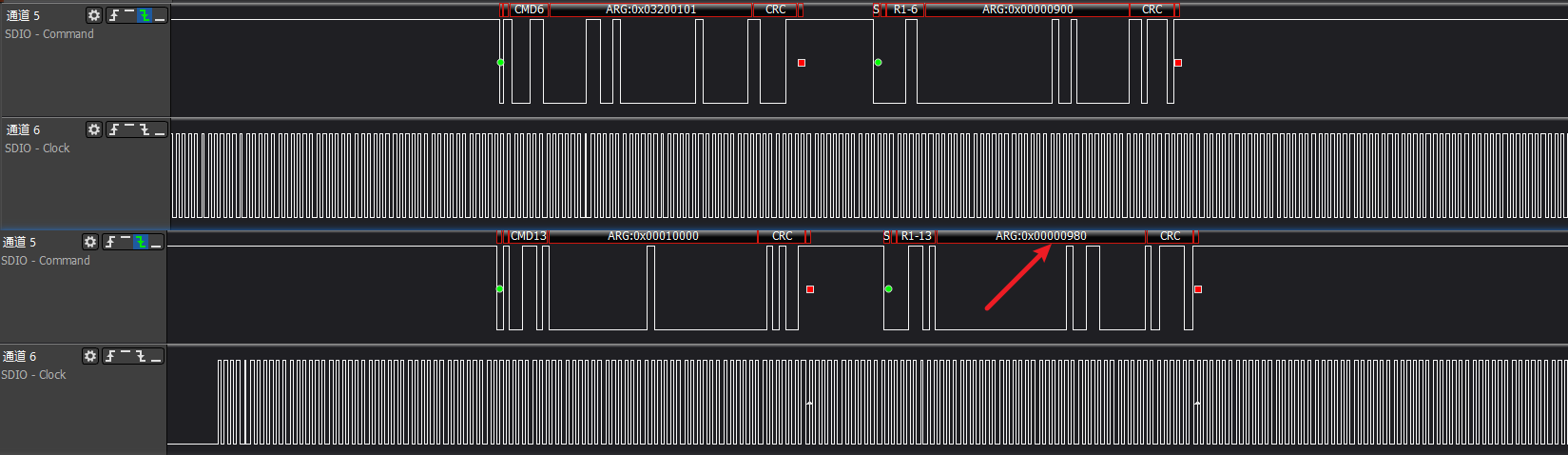
cmd6 command is special, its rsp is r1b type, cmd6 command execution error needs immediately following cmd13 response to feed back error status
In figure is switch error, cmd13 rsp status shows as '980', i.e., device switch error
>>>emmc boot
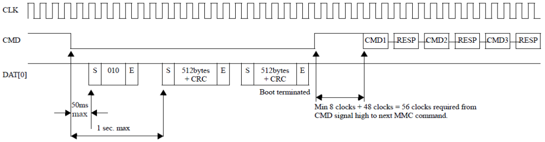
SPEC规定 emmc boot uses cmd0(ARG:0xfffffffa) to request boot data, needs to send data back to host within specified 1s time, otherwise determined as abnormal
>>>emmc isptool
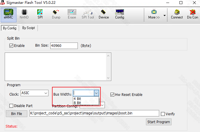
Old version isptool will require manual selection of bus width, here should match boot strap cap selection on board, new version tool automatically keeps consistent
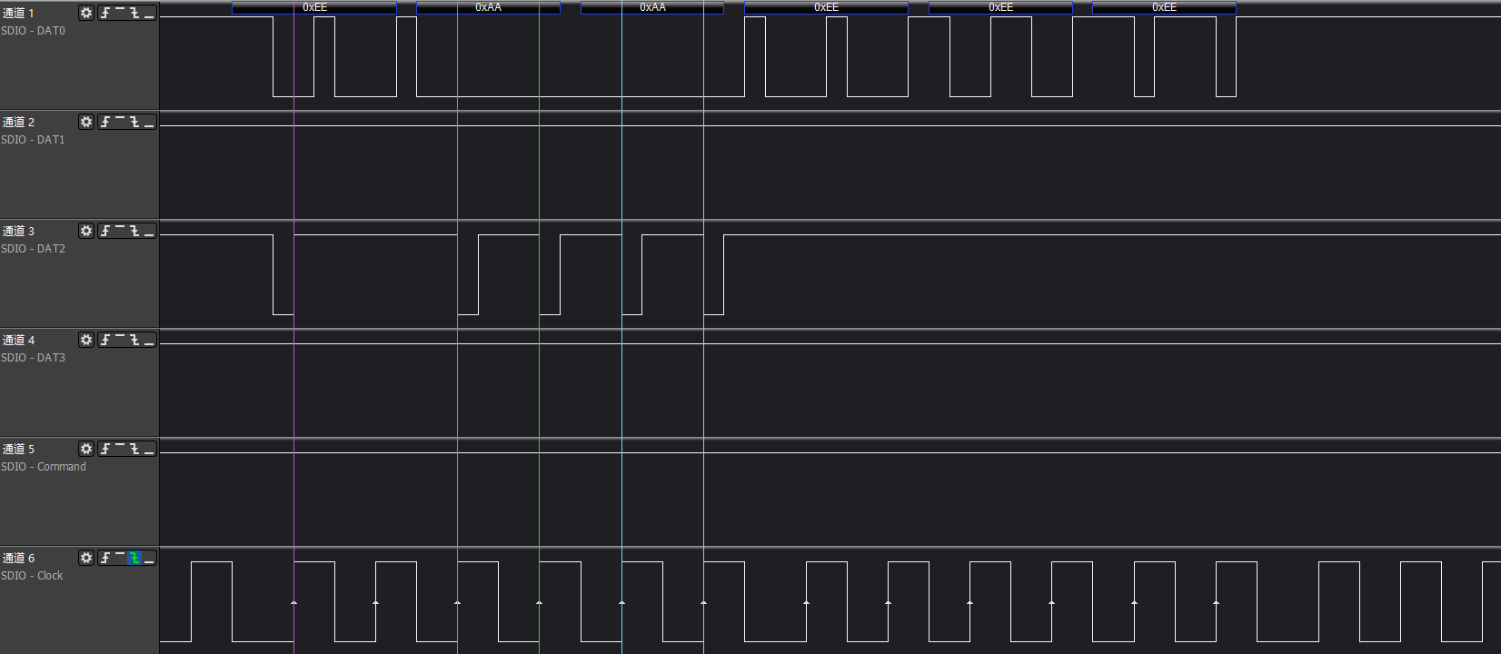
>>>emmc boot ack
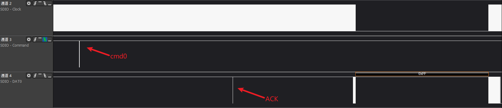
In emmc boot ack enable situation, device will send acknowledge pattern '010' within 50ms after cmd0 issued to indicate card has entered boot mode
>>>Common timing issue 1: When cmd sent, clk is turned off
>>>Common timing issue 2: When cmd sent, clk abnormal, causing cmd not recognized normally
>>>Common timing issue 3: ESD/high-low temperature etc. external interference causes clk abnormal
>>>Common timing issue 4: clk has almost no sampling setup time, easy to cause misjudgment
Timing issues are generally complex, need hardware FAE involvement to provide solutions, common software methods generally include adjusting phase, improving driving capability, spread spectrum etc.