Sensor Click Program Description
1. Introduction to Sensor Image Display Functionality
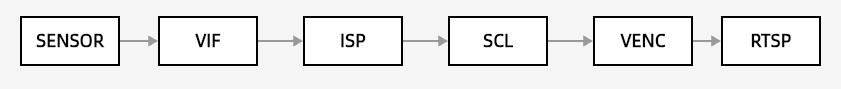
This demo primarily demonstrates how to connect the entire pipeline from Sensor to Rtsp, as shown in the diagram above. specifically supporting the following functionalities:
-
Functional Scene: The video collected by the sensor is displayed on the rtsp
-
Video Stream: sensor->vif->isp->scl->venc->rtsp
-
Supports dual-camera configuration
-
Supports configuration of the iqbin path
2. Compilation Environment Description
Note
Generally, the corresponding programs have already been packaged on the board by default, so program compilation is not mandatory. You can directly find prog_vif_sensor_demo in the /customer/sample_code/vif/sensor_demo folder on the board. If you cannot find the file or have a need to modify the program, you can refer to the following steps.
-
If
prog_vif_sensor_demois not found, you can check ifAPP_REL_PREFIX:= binis included in\sdk\verify\sample_code\source\iford\vif\sensor_demo\sensor_demo.mk. If it is not, you can add it to sensor_demo.mk, so that it will be packaged into the image during the project compilation. -
In the project path, select defconfig for the board (nand/nor, ddr model, etc.) to perform a full package compilation.
For example, for Comake PI D2 model board using emmc and ddr4 configuration, use the following defconfig; for other board models, refer to the user manual:
ipc_iford.emmc.glibc-11.1.0-ext4fs.ssc029d.256.bga8_lpddr4x_d2_full_defconfigExecute the following commands in the project directory for compilation:
export PATH=/tools/toolchain/gcc-sigmastar-9.1.0-2019.11-x86_64_arm-eabi/bin:/tools/toolchain/gcc-11.1.0-20210608-sigmastar-glibc-x86_64_arm-linux-gnueabihf/bin:$PATHexport CROSS_COMPILE=arm-linux-gnueabihf-export ARCH=armmake ipc_iford.emmc.glibc-11.1.0-ext4fs.ssc029d.256.bga8_lpddr4x_d2_full_defconfigmake clean && make image -j8 -
Navigate to the
sdk/verify/sample_codedirectory and executemake clean && make source/iford/vif/sensor_demofor compilation; -
Go to
sample_code/out/arm/app/prog_vif_sensor_demoto get the executable file; -
Place the executable file
prog_vif_sensor_demoon the board at the path/customer/sample_code/binand change the permissions to 777.
3. Runtime Environment Description
3.1 Single sensorRuntime Environment Description
-
Board Environment
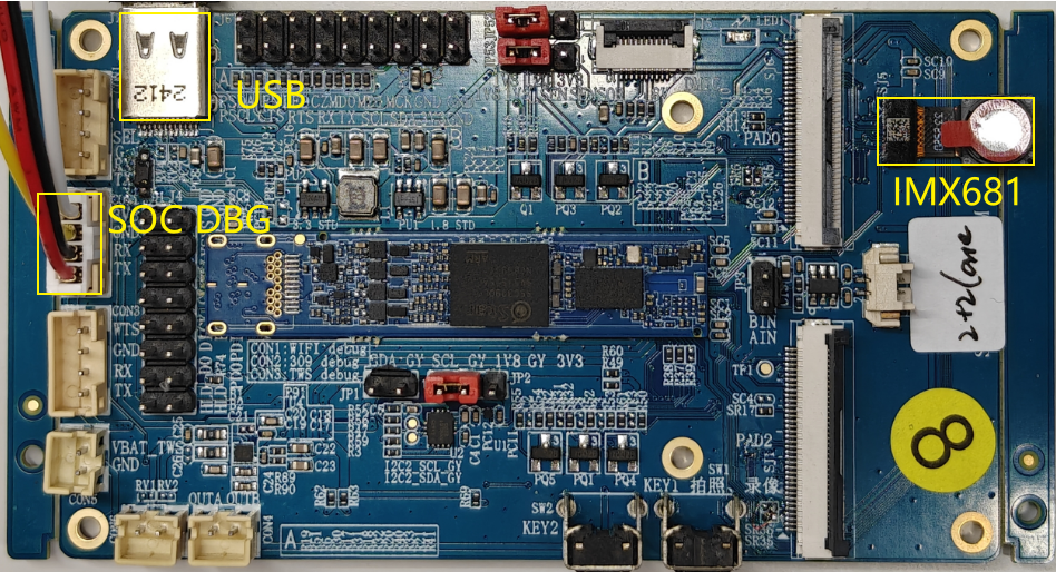
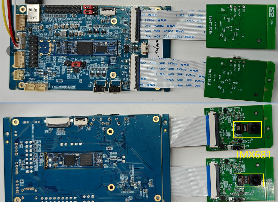
There are two connection methods for the single sensor: one is the default SJ5 IMX681 SENSOR, and the other is connecting the IMX681 SENSOR to SJ6. For details, refer to the Comake Pi D2 Hardware Description section 3.15 MIPI01 PAD2 2LANE Interface (SJ1).
The SJ5 connection to the sensor is shown in the figure below.
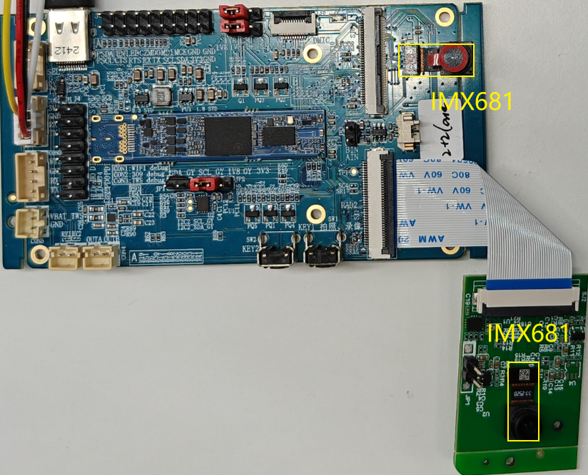
The SJ6 connection to the sensor is shown in the figure below.

-
DTS configuration:
Using the MIPI SNR0 2-lane development board with the corresponding defconfig for D2 full, the default DTS is already configured and does not require modification.
-
Sensor Driver Configuration
Modify the path in
/customer/demo.shto correspond to the insmod of the appropriate sensor kernel object (KO). For example, for the IMX618 sensor, you can configure it as follows:insmod /config/modules/5.10/imx618_MIPI.ko chmap=1 (for running a single sensor)
3.2 Dual sensor
-
Board Environment
The dual sensor connection requires SJ1/SJ5/SJ6, and you can choose the SJ5-SJ1 combination or the SJ6-SJ1 combination, with the SJ6-SJ1 combination requiring hardware modifications.For details, refer to the Comake Pi D2 Hardware Description section 3.15 MIPI01 PAD2 2LANE Interface (SJ1).
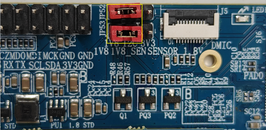
To maintain a stable high frame rate, such as 1080P60, the expansion board needs to provide power to the sensor as shown in JP53, and the I2C requires 1V8 power supply as indicated in JP52.
The connection between SJ5 and SJ1 sensors is shown below.
The connection between SJ6 and SJ1 sensors is shown below.
Note: The MIPI cable should not be connected in reverse, as it may damage the sensor.
-
DTS configuration:
Confirm the DTS configuration of the
\kernel\arch\arm\boot\dts\iford-ssz029d-s01a-d2-full-camdriver.dtsifile.csi: csi { compatible = "sstar,csi"; io_phy_addr = <0x1f000000>; banks = <0x153C>,<0x153D>,<0x153E>,<0x1538>,<0x153A>,<0x153B>; atop_banks = <0x153F>; clkgen_banks = <0x1038>; interrupts= <GIC_SPI INT_IRQ_MIPI_CSI2 IRQ_TYPE_LEVEL_HIGH>; clocks = <&CLK_csi0_mac_lptx_top_i>, <&CLK_csi0_mac_top_i>, <&CLK_csi0_ns_top_i>, <&CLK_csi1_mac_lptx_top_i>, <&CLK_csi1_mac_top_i>, <&CLK_csi1_ns_top_i>; status = "ok"; /* Config max lane number */ csi_sr0_lane_num = <2>; csi_sr2_lane_num = <2>; /* Config lane selection */ csi_sr0_lane_select = <2 1 0 3 4>; csi_sr2_lane_select = <2 1 0>; /* Config lane P/N swap */ csi_sr0_lane_pn_swap = <0 0 0 0 0>; csi_sr2_lane_pn_swap = <0 0 0>; }; sensorif: sensorif { compatible = "sstar,sensorif"; clocks = <&CLK_sr00_mclk>, <&CLK_sr01_mclk>; snr0_mipi_i2c = <1>; snr2_mipi_i2c = <2>; /* Config sensor 0 pad mux */ snr_sr0_mipi_mode = <5>; snr_sr0_mipi_rst_mode = <1>; snr_sr0_rst_pol = <1>; snr_sr0_mipi_pdn_mode = <0>; snr_sr0_mipi_mclk_mode = <1>; snr_sr0_rst_gpio = <PAD_SR_RST0>; /* Config sensor 2 pad mux */ snr_sr2_mipi_mode = <5>; snr_sr2_mipi_rst_mode = <1>; snr_sr2_rst_pol = <1>; snr_sr2_mipi_pdn_mode = <0>; snr_sr2_mipi_mclk_mode = <1>; snr_sr2_rst_gpio = <PAD_SR_RST1>; /* Config mclk 37.125MHz supported */ vif_sr0_mclk_37p125 = <1>; vif_sr2_mclk_37p125 = <1>; /*config mipi pwm */ snr_ds_rt_snr_pad = <0 2>; snr_ds_rt_pwm_sync = <0>; snr_ds_rt_pwm_pin = <8>; snr_ds_rt_pwm_sr0_pol = <0>; snr_ds_rt_pwm_sr1_pol = <1>; snr_ds_rt_pwm_cycle = <60>; };The MIPI SNR0+SNR1 2+2 lane development board is used with the corresponding defconfig for D2 full. The default DTS is configured correctly and does not require any modifications.To use the PWM dual sensor,simply set snr_ds_rt_pwm_sync to 1.
-
Sensor Driver Configuration
Modify the path in
/customer/demo.shto correspond to the insmod of the appropriate sensor kernel object (KO). For example, for the IMX618 sensor, you can configure it as follows: insmod /config/modules/5.10/imx618_MIPI.ko chmap=5 (for running a dual sensor)
4. Execution Instructions
Execute cd /customer/sample_code/bin to navigate to the corresponding file path.
Parameter explanation as follows:
| Parameter Description | Function | Remarks |
|---|---|---|
| cmdIndex | Enabled sensor | 0: Single sensor, 1: Dual sensor |
| index | Select sensor resolution | If this parameter is not entered, the program will automatically output all available resolutions for selection |
| iqbin | Load the path of iqbin | Default storage path on the board: /config/iqfile/ |
| 3dnr | Enable 3DNR | 0: Off, 1: On |
| realtime | Enable real-time mode | 0: Frame mode (default), 1: Real-time mode. Note: When using dual channels, enabling real-time mode only supports PWM control of dual slaves, and DTS needs to be modified. Refer to section 3.2 for DTS configuration details. The resolution only supports those with slave_pwm_low and slave_pwm_high. |
| calidata | Load the path of calidata | Default storage path on the board: /config/iqfile/ |
| q | Enable IQ server functionality | For details, please refer to ISP API Tuning SOP |
-
index + sensorIndex
Execute
./prog_vif_sensor_demo 0 index 1. The first parameter selects a single sensor, the second parameter isindex, and the third parameter input is to choosesensorIndex, which ranges from0-13. For the resolution list, refer to the example table below.index0/index5are picture formats, which are not currently supported by VENC resource streams.index11/index12are for selecting the PWM dual sensor, and the DTS needs to be modified to enable the switch.index 0, Crop(0,0,4032,3024), outputsize(4032,3024), maxfps 15, minfps 3, ResDesc 4032x3024@15fps index 1, Crop(0,0,3840,2160), outputsize(3840,2160), maxfps 21, minfps 3, ResDesc 3840x2160@21fps index 2, Crop(0,0,2016,1512), outputsize(2016,1512), maxfps 30, minfps 3, ResDesc 2016x1512@30fps index 3, Crop(0,0,1920,1080), outputsize(1920,1080), maxfps 30, minfps 3, ResDesc 1920x1080@30fps index 4, Crop(0,0,3264,2448), outputsize(3264,2448), maxfps 30, minfps 3, ResDesc 3264x2448@30fps index 5, Crop(0,0,4032,3024), outputsize(4032,3024), maxfps 30, minfps 3, ResDesc 4032x3024@30fps index 6, Crop(0,0,3840,2160), outputsize(3840,2160), maxfps 30, minfps 3, ResDesc 3840x2160@30fps index 7, Crop(0,0,1920,1080), outputsize(1920,1080), maxfps 60, minfps 3, ResDesc 1920x1080@60fps index 8, Crop(0,0,1008,756), outputsize(1008,756), maxfps 200, minfps 3, ResDesc 1008x756@200fps index 9, Crop(0,0,2560,1440), outputsize(2560,1440), maxfps 30, minfps 3, ResDesc 2560x1440@30fps index 10, Crop(0,0,1920,1080), outputsize(1920,1080), maxfps 60, minfps 3, ResDesc 1920x1080@60fps_master_xvs index 11, Crop(0,0,1920,1080), outputsize(1920,1080), maxfps 60, minfps 3, ResDesc 1920x1080@60fps_slave_pwm_low index 12, Crop(0,0,1920,1080), outputsize(1920,1080), maxfps 60, minfps 3, ResDesc 1920x1080@60fps_slave_pwm_high choice which resolution use, cnt 13 -
iqbin + iqBinPath
Execute
./prog_vif_sensor_demo 0 iqbin /config/iqfile/imx681_3m_comake_1201_30fps.binwith the first choise single senor,the second parameter iqbin, and the third parameter should be the file path of iqbin; or if the second parameter is index, the third parameter should be SensorResNum, the fourth parameter should be iqbin, and the fifth parameter should be the file path of iqbin.
Notice
When selecting the IQ BIN, please refer to the following table corresponding to the resolution.
| Resolution | IQ File | Calidata | Notes |
|---|---|---|---|
| 4032x3024@15fps | NA | NA | Not supported |
| 3840x2160@21fps | imx681_8m_comake_1201_30fps.bin | 12m_ne_cali.data | NA |
| 2016x1512@30fps | imx681_3m_comake_1201_30fps.bin | 3m_ne_cali.data | NA |
| 3264x2448@30fps | imx681_8m_comake_1201_30fps.bin | 12m_ne_cali.data | NA |
| 4032x3024@30fps | NA | NA | Not supported |
| 3840x2160@30fps | imx681_8m_comake_1201_30fps.bin | 12m_ne_cali.data | NA |
| 1920x1080@60fps | imx681_2m_comake_1201_60fps.bin | 3m_ne_cali.data | NA |
| 1920x1080@30fps | imx681_2m_comake_1201_30fps.bin | 3m_ne_cali.data | NA |
| 1920x1080@60fps_slave_pwm_low | imx681_2m_comake_1201_60fps_8ms.bin | 3m_ne_cali.data | Need to enable realtime, modify DTS |
| 1920x1080@60fps_slave_pwm_high | imx681_2m_comake_1201_60fps_8ms.bin | 3m_ne_cali.data | Need to enable realtime, modify DTS |
Execution example
-
Configure the USB as an RNDIS network card. Change directory to
/customer/sample_code/bin/resourceand run./setup_rndis.sh. By default, this will bring up the usb0 network interface. Enterifconfig.usb0 Link encap:Ethernet HWaddr E6:46:AC:2F:77:56 inet addr:192.168.7.2 Bcast:192.168.7.255 Mask:255.255.255.0 UP BROADCAST RUNNING MULTICAST MTU:1500 Metric:1 RX packets:48 errors:0 dropped:31 overruns:0 frame:0 TX packets:0 errors:0 dropped:0 overruns:0 carrier:0 collisions:0 txqueuelen:1000 RX bytes:3400 (3.3 KiB) TX bytes:0 (0.0 B)At this point, the PC will enumerate a virtual RNDIS network card, which can be viewed by going to "Right-click -> Start -> Device Manager -> Network Adapters". It is typically named
USB Ethernet/RNDIS Gadget. If this device is not present, it may indicate that the RNDIS driver is not installed on the computer. You can refer to Chapter 4 of the following link for installation instructions:https://dev.comake.online/home/article/7672 -
Run the single sensor example:
./prog_vif_sensor_demo 0 index 3 iqbin /config/iqfile/imx681_3m_comake_1201_30fps.bin 3dnr 1 calidata /config/iqfile/3m_ne_cali.dataRun the dual sensor example:
./prog_vif_sensor_demo 1 index 3 iqbin /config/iqfile/imx681_3m_comake_1201_30fps.bin 3dnr 1 calidata /config/iqfile/3m_ne_cali.dataRun the pwm dual sensor example:
./prog_vif_sensor_demo 1 realtime 1 iqbin /config/iqfile/imx681_2m_comake_1201_60fps_8ms.bin 3dnr 1 calidata /config/iqfile/3m_ne_cali.dataAfter running the demo, it will print the available resolutions for the sensor. Input the resolution index you want to select for preview (sensor resolution). For example, for the imx415 sensor, the following log will be printed:
-
Note: For the same model of sensor running dual streams, please enter the same resolution index.
index 0, Crop(0,0,4032,3024), outputsize(4032,3024), maxfps 15, minfps 3, ResDesc 4032x3024@15fps index 1, Crop(0,0,3840,2160), outputsize(3840,2160), maxfps 21, minfps 3, ResDesc 3840x2160@21fps index 2, Crop(0,0,2016,1512), outputsize(2016,1512), maxfps 30, minfps 3, ResDesc 2016x1512@30fps index 3, Crop(0,0,1920,1080), outputsize(1920,1080), maxfps 30, minfps 3, ResDesc 1920x1080@30fps index 4, Crop(0,0,3264,2448), outputsize(3264,2448), maxfps 30, minfps 3, ResDesc 3264x2448@30fps index 5, Crop(0,0,4032,3024), outputsize(4032,3024), maxfps 30, minfps 3, ResDesc 4032x3024@30fps index 6, Crop(0,0,3840,2160), outputsize(3840,2160), maxfps 30, minfps 3, ResDesc 3840x2160@30fps index 7, Crop(0,0,1920,1080), outputsize(1920,1080), maxfps 60, minfps 3, ResDesc 1920x1080@60fps index 8, Crop(0,0,1008,756), outputsize(1008,756), maxfps 200, minfps 3, ResDesc 1008x756@200fps index 9, Crop(0,0,2560,1440), outputsize(2560,1440), maxfps 30, minfps 3, ResDesc 2560x1440@30fps index 10, Crop(0,0,1920,1080), outputsize(1920,1080), maxfps 60, minfps 3, ResDesc 1920x1080@60fps_master_xvs index 11, Crop(0,0,1920,1080), outputsize(1920,1080), maxfps 60, minfps 3, ResDesc 1920x1080@60fps_slave_pwm_low index 12, Crop(0,0,1920,1080), outputsize(1920,1080), maxfps 60, minfps 3, ResDesc 1920x1080@60fps_slave_pwm_high choice which resolution use, cnt 13- Note that for the same model sensor running dual streams, please enter the same resolution index. In PWM dual slave mode, choose index 11 and index 12 respectively.
5. Execution Result Description
-
preview Single sensor effect view
Normal output flow will print the RTSP URL. A single sensor will print one URL, while dual sensors will print two URLs. For example, the following log:
Use video playback software such as VLC Media Player or PotPlayer to play using the link. If playback is successful, you will see the sensor image.
=================URL===================
rtsp://192.168.7.2/6600
=================URL===================
Create Rtsp H265 Session, FPS: 30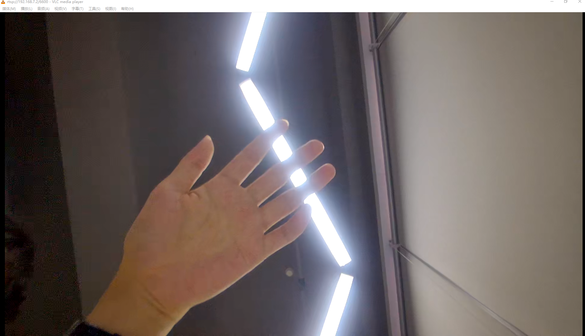
-
Dual sensor effect view
=================URL===================
rtsp://192.168.7.2/6600
=================URL===================
Create Rtsp H265 Session, FPS: 60
(ST_DualSensorPipline_Preview 467)exec function pass
rtsp venc dev0, chn 1, type 3, url 6601
video width: 1920, height: 1080, Max buf size: 0xfd200
=================URL===================
rtsp://192.168.7.2:555/6601
=================URL===================
Create Rtsp H265 Session, FPS: 60
-
Exit Command
Enter
qto quit the demo, it will exit the sensor0's captured image, displaying black.