Sensor Debug SOP
REVISION HISTORY
| Revision No. | Description |
Date |
|---|---|---|
| 1.0 | 06/19/2024 | |
| 1.1 | 07/05/2024 | |
| ---- |
Introduction
This document is written for FAE and software development personnel, aiming to introduce how to perform preliminary investigation when customers encounter Sensor-related issues during development, and what information needs to be provided to RD for analysis after determining it is a Sigmastar SDK issue.
1. Common Basic Operations and Commands for Sensor Debugging
1.1 Sensor Setting Information
-
Debug information
#cat /proc/mi_modules/mi_sensor/debug_hal/sensor_info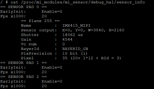
-
Debug information analysis
Records sensor pad related information.
-
Parameter description
Parameter Description EarlyInit Enable EarlyInit enable or not Fps x1000 Frame rate (fps) Plane Name Sensor name Sensor output Output width and height Shutter Sensor shutter Gain Sensor gain Vc num HDR channel number BayerId Bayer id PixPrecision Bayer id Pixel Pixel format -
Debug description
1.2 Confirm MIPI CSI Receive Information
-
Debug information
#cat /proc/mi_modules/mi_sensor/debug_hal/csi_info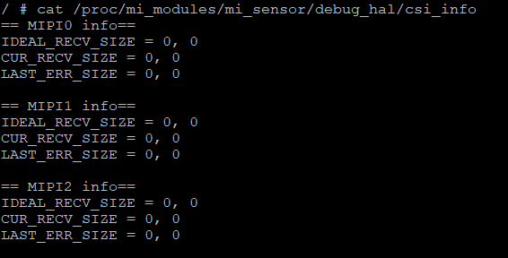
-
Debug information analysis
Check MIPI related information.
-
Parameter description
Parameter Description IDEAL_RECV_SIZE Ideally received (width, height) CUR_RECV_SIZE Currently received (width, height) LAST_ERR_SIZE When Mac layer has line end interrupt and currently received width and height do not match ideally received width and height, records the current (width, height).
1.3 Confirm MIPI CSI Error Interrupt Status
-
Debug information
#echo <Sensor Pad> <csi_err_mask> > cat /proc/mi_modules/mi_sensor/debug_hal/csi_dbg_mask
#echo <Sensor Pad> <csi_rpt_mask> > cat /proc/mi_modules/mi_sensor/debug_hal/csi_rpt_mask
#cat cat /proc/mi_modules/mi_sensor/debug_hal/csi_ints

<csi_err_mask>: Mask bit description as follows
[14]: overrun_err
[13]: ls_err
[12]: le_err
[11]: con_fs_err (consecutive fs)
[10]: con_fe_err (consecutive fe)
[9]: raw10_lens_err (not 5n alignment)
[8]: pa_wc_eq0 (payload word count equal to 0)
[7]: crc error
[6]: ecc 2bit error
[5]: frame end error
[4]: frame start error (hardware auto-ignore)
[3]: ecc 1bit error (hardware auto-correct)
[2]: ph_lens_err (packet header lengths error)
[1]: pa_lens_err (payload lengths error shorter than wc)
[0]: dt_err (reserved and not supported data type)

<csi_rpt_mask>: Mask bit description as follows
[6]: report vc0 frame done
[5]: report vc1 frame done
[4]: report vc2 frame done
[3]: report vc3 frame done
[2]: report generic 8 bit short packet data
[1]: report frame number
[0]: report line number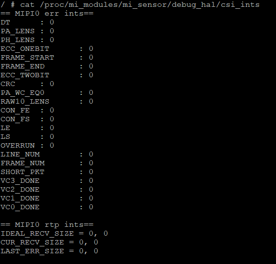
-
Debug information analysis
Check the occurrence count of csi_err and csi_rpt related interrupts. Typically when MIPI sensor VIF receives data abnormally, this command can be used to analyze the issue.
-
Parameter description
| Parameter | Description | |
|---|---|---|
| CSI_ERR | DT | Unsupported data type | PA_LENS | Packet payload length abnormal, shorter than WC |
| PH_LENS | Packet header length abnormal, normally 32 bits | |
| ECC_ONEBIT | ECC 1 bit abnormal, hardware auto-correct | |
| FRAME_START | Frame start abnormal | |
| FRAME_END | Frame end abnormal | |
| ECC_TWOBIT | ECC two bit abnormal | |
| CRC | CRC check abnormal | |
| PA_WC_EQ0 | Packet payload word count equal to 0 | |
| RAW10_LENS | Not used | |
| CON_FE | Consecutive frame end abnormal | |
| CON_FS | Consecutive frame start abnormal | |
| LE | Line end abnormal | |
| LE | Line start abnormal | |
| OVERRUN | TX faster than RX | |
| CSI_RPT | LINE_NUM | Report line number |
| FRAME_NUM | Report frame number | |
| SHORT_PKT | Report generic 8 bit short packet data | |
| VC3_DONE | Report VC3 frame done | |
| VC2_DONE | Report VC2 frame done | |
| VC1_DONE | Report VC1 frame done | |
| VC0_DONE | Report VC0 frame done | |
2. Basic Analysis of Common Issues
2.1 ISP FIFO FULL
Case A. When ISP reports ISP FIFO FULL is because previous stage VIF has insufficient data, can first investigate Sensor output signals
    a. Confirm not executing app, only execute cmd: echo enable "snrpad" > /dev/sensorif
       Example:
       snrpad 0

       echo enable 0 > /dev/sensorif

    b. Then through the MIPI CSI debug interface described above, confirm if corresponding MIPI CSI information is correct
    c. If incorrect, can first investigate if MIPI CSI signal timing meets our specifications, and provide MIPI CSI info and MIPI error interrupt status information to SW RD for confirmation
Case B. When linear frame mode outputs normally, but realtime mode encounters ISP FIFO FULL, can first investigate Sensor output signals
       Example:
       Frame rate 30fps, represents frame interval of 33.3ms, measure MIPI CSI signal data pins,
       confirm the ratio of valid data and blanking, hope to set blanking to about 1ms for best results
Case C. When hdr frame mode outputs normally, but realtime mode encounters ISP FIFO FULL
    a. Confirm ISP ring mode setting size
    b. Read sensor short exposure information, check if it's greater than ISP ring mode setting size
       Example:
       ISP ring size set to 1/8:
       Image height is 1080, so 1080 x (1/8) = 135

       Represents that short exposure cannot exceed the time of 135 lines, otherwise there will be ISP P1 FIFO FULL error

       Additional note:
       HDR long exposure data is output first, followed by short exposure data. The time from the start of long exposure to the start of short exposure is the adjustable exposure time for short exposure.
       In HDR realtime mode, long exposure data coming in is first written to wdma. This wdma is ring buf mechanism, while short exposure is directly output to ISP.
       Using the above example, when incoming long exposure lines count writes from 0 to 134 lines, the 135th line will return to the source and overwrite.
       If short exposure comes later, ISP will encounter situation where data from long exposure and short exposure cannot match, causing ISP P1 FIFO FULL error.
Case D. When HDR Frame mode outputs normally, but Realtime mode encounters ISP FIFO FULL, accompanied by purple blocks on the left
a. Issue of long and short exposure not synchronized, recommend feedback to SW RD