UART User Guide
REVISION HISTORY
| Revision No. | Description |
Date |
|---|---|---|
| 1.0 | 07/21/2023 | |
| 1.1 | 11/08/2025 |
1. Overview
1.1 UART
UART refers to Universal Asynchronous Receiver/Transmitter, generally known for its asynchronous and serial communication characteristics. The UART bus has two data lines, TX and RX, for full-duplex transmission and reception. The transmitter and receiver parse the received signal through the frame format and baud rate set respectively, so the transmitter and receiver should use the same frame format and baud rate during the communication process.
1.2 SigmaStar UART
The SigmaStar UART is a module that is integrated in the chip and conforms to the standard serial communication protocol. This module contains multiple UARTs, called FUART and UART. The difference between these two types of UART is that, FUART has more CTS/RTS hardware flow control functions than UART. All UARTs support DMA mode. Generally, UART0 is used as the console port by default.
2. Keyword Description
-
TX
Data transmission function/pin, which transmits UART signal according to the set frame format and baud rate.
-
RX
Data reception function/pin. The received signal will be parsed by UART with the set frame format and baud rate. TX and RX share the same set of settings.
-
CTS
Flow control pin/signal. It is an input signal, interpreted as a "Clear To Send" and used to judge whether data can be sent to the other side. This signal is active low.
-
RTS
Flow control pin/signal. It is an output signal, interpreted as a "Request To Send" and used to indicate that the device is ready to receive data. This signal is active low.
-
FIFO mode
For transmit operation, each frame of data needs to be passed to the UART hardware transmit buffer register through the CPU, so that the UART can take and send it out from the transmit buffer. The hardware transmit buffer is 32 bytes. For receive operation, the CPU reads the data from the UART hardware receive buffer register, and the hardware receive buffer is 32 bytes.
-
DMA mode
For transmit operation, the data of each frame does not need to be sent or read by the CPU one by one. It is only necessary to write the data to be sent into the storage location designated by the DMA at one time before triggering the communication, and then trigger the communication. For receive operation, the receiver can get the data from the designated storage location at one time. During communication execution, data interaction between UARTs is completed by URDMA without CPU involvement.
DMA mode can make the transmission more coherent, reduce CPU loading, and decrease the number of UART communication interruptions. Moreover, it can realize simultaneous data reception and transmission through 4096 bytes of storage space, which can greatly reduce the possibility of data loss.
-
URDMA
A module dedicated to providing data transfer services for UART, which needs to be enabled in DMA mode. When this module is enabled, UART no longer interrupts; there is only URDMA interrupt. If DMA is enabled, CPU can no longer access UART registers; otherwise, it will cause the communication to get stuck.
-
CONSOLE PORT
The term console is a concept of buffering, which is specially used for the kernel to provide printing and busybox to receive shell commands. The PC is connected to the Console Port, and the terminal application of the PC is used to display the printed information or input the execution command.
-
PADMUX
Pin multiplexing, which connects the UART PAD to the actual pin, so that the signal can be transmitted through the pin.
-
DIGMUX
DIGMUX is used to connect UART TX/RX digital message and UART PAD. Different UART PADs can be connected to different UART modules. However, PAD_PM_UART_TX and PAD_PM_UART_RX which are the default console ports cannot be switched through digmux.
For example, when the hardware layout is fixed, assuming that the function of UART1 is used originally, and the support of HW CTS/RTS is required at this time, but the FUART does not have the corresponding PADMUX to switch to this group of hardware pins. Then you can switch UART1 and FUART by switching DIGMUX. By so doing, the signal connections of the TX/RX of FUART and the TX/RX of UART1 are interchanged, but the CTS/RTS is still the original pin set by FUART, which meets the requirements for HW CTS/RTS usage.
3. Function Description
3.1 UART Resource
2 UARTs and 1 FUART are provided, all of which support DMA mode, but only FUART supports HW CTS/RTS.
Each UART/URDMA corresponds to the bank address set forth below. UART and URDMA are uniquely bound, for example, FUART is bound to URDMA, and UART0 is bound to URDMA0:
| UART IP | FUART | UART0 | UART1 |
|---|---|---|---|
| BANK ADDR | 1102 | 1108 | 1109 |
| URDMA IP | URDMA | URDMA0 | URDMA1 |
|---|---|---|---|
| BANK ADDR | 1102 | 1107 | 110E |
3.2 Function Support
The following table provides the support of each UART for each function:
| Function | FIFO Mode | FIFO Buffer Size (byte) | DMA mode | DMA Buffer Size (byte) | HW CTS/RTS | Baud Rate | Protocol |
|---|---|---|---|---|---|---|---|
| Supportability | ✔ | 32 | ✔ | 4096 | Only FUART | ✔ | ✔ |
The baud rate support is as follows:
UART |
Baud Rate (bps) |
|---|---|
| ALL UART | 1200 |
| ALL UART | 1800 |
| ALL UART | 2400 |
| ALL UART | 4800 |
| ALL UART | 9600 |
| ALL UART | 19200 |
| ALL UART | 38400 |
| ALL UART | 57600 |
| ALL UART | 115200 |
| ALL UART | 230400 |
| ALL UART | 460800 |
| ALL UART | 500000 |
| ALL UART | 576000 |
| ALL UART | 921600 |
| ALL UART | 1000000 |
| ALL UART | 1152000 |
| ALL UART | 1500000 |
| ALL UART | 2000000 |
| ALL UART | 2500000 |
| ALL UART | 3000000 |
The UART communication protocol support is as follows:
UART |
start bits | char bits | even parity | stop bits |
|---|---|---|---|---|
| ALL UART | 1 bit | 5 bits;6 bits; 7 bits; 8 bits | Y/N | 1 bit; 1.5 bits |
The communication timing diagram is shown in Figure 3-1:

3.3 Notes
-
External Pull-up
RX must be connected to an external pull-up, and TX is recommended to be connected to an external pull-up.
-
FIFO mode
When using FIFO mode, the HW buffer size is only 32 bytes. If the UART cannot respond to the UART interrupt in time before the buffer is filled, thus causing the data in the HW buffer to be read out, the received data might be lost.
3.4 Baud Rate Calculation
Baud rate refers to the modulation rate of the data signal to the carrier, which is expressed by the number of carrier modulation state changes per unit time, and is an important indicator of UART. The actual output baud rate of the current hardware UART is determined by the clock source input to the UART and the set frequency division value. The relationship between baud rate (BAUD), frequency division value (DIV) and input clock frequency (CLK) is as follows:
DIV = CLK / (BAUD × 16)
Since the clock rate given to the UART is not continuous, the baud rate (with 3% error) that the UART can support according to the above formula is not continuous either.
Baud Rate Modification
Baud rate can be set in user space applications.
It can also be modified through the stty command. For example, to modify the baud rate of UART1 to 115200:
1. stty -F /dev/sttyS1 ospeed 115200
4. Hardware connection

5. Uboot usage introduction
5.1 Configuration
When using UART under uboot, SigmaStar UART driver compilation is required, which is built-in by default because the console driver is also in the uart driver. In addition, you need to enable CONFIG_DM_SERIAL, as follows:
Device Drivers --->
    Serial drivers --->
        (1) UART used for console
        [*] Enable Driver Model for serial drivers
        [ ]   Enable RX buffer for serial input
        [ ]   Search for serial devices after default one failed
        [ ]   Probe all available serial devices
Just enable 'Enable Driver Model for serial drivers', and 'UART used for console' will be automatically selected.
5.2 Driver Path
drivers/sstar/uart/drv_uart.c
drivers/sstar/uart/drv_uart.h
drivers/sstar/uart/os/os_uart.h
drivers/sstar/uart/iford/hal_uart.c
drivers/sstar/uart/iford/hal_uart.h
drivers/sstar/uart/iford/hal_uart_cfg.h
5.3 DTS Definition
uart0: uart0@1F221000 {
    compatible = "sstar,uart";
    reg = <0x1F221000 0x100>;
    group = <0>;
    char-bits = <8>;
    stop-bits = <1>;
    parity-en = <0>; // 0-disable; 1-odd; 2-even.
    tolerance = <3>;
    status = "okay";
};

uart1: uart1@1F221200 {
    compatible = "sstar,uart";
    reg = <0x1F221200 0x200>;
    group = <1>;
    char-bits = <8>;
    stop-bits = <1>;
    parity-en = <0>; // 0-disable; 1-odd; 2-even.
    tolerance = <3>;
    status = "okay";
};
| Attribute | Description |
Note |
|---|---|---|
| compatible | Used to match the driver | Modification not allowed |
| reg | IO_address Address_size | Modification not allowed |
| group | UART group number | Modification not required |
| rate | Baud rate | If you need to specify, you can add attributes to the node, or call the API to dynamically adjust during use |
| char-bits | Data bits | If this attribute is not present, the default is 8 bits |
| stop-bits | Stop bits | If this attribute is not present, the default is 1 bits |
| parity-en | Parity check | If this attribute is not present, no parity is used by default 0 : no parity 1 : odd parity 2 : even parity |
| tolerance | baud rate tolerance percentage | The number N represents N% If this attribute is not present, the default is 3% |
| status | Node enable, used to determine whether to enable the UART | "okay": enabled "disabled": disabled |
5.4 Pin Multiplexing
PADMUX, which is used to connect the UART signal to a specific group of pins. The settings are modified in iford-xxx-padmux.dtsi for unified management. The first column is the pin number definition, the second column is the padmod number of the pin multiplexing, and the third column puse is the function definition. It should be noted that the pin numbers in the first column cannot be repeated, otherwise the compilation test will fail; the corresponding padmod number in the second column must match the pin number. If they do not match, the compilation will also fail.
arch/arm/dts/iford-ssc029a-s01a-padmux.dtsi

padmux {
        compatible = "sstar,padmux";
        schematic =
        ...
        <PAD_PM_FUART_RX        PINMUX_FOR_FUART_2W_MODE_2   MDRV_PUSE_FUART_RX>,
        <PAD_PM_FUART_TX        PINMUX_FOR_FUART_2W_MODE_2   MDRV_PUSE_FUART_TX>,
        ...
        };
5.5 Software Usage Process
The DM architecture will automatically match the device and driver during the startup process. If the match is successful, the '.of_to_plat' and '.probe' methods will be automatically executed to complete the initialization and setting of the software and hardware. Therefore, when using it, what we need to do is: get the uclass device, get the ops method, and call the corresponding function pointer to perform the operation.
// uclass_id must be UCLASS_SERIAL
ret = uclass_get_device_by_seq(UCLASS_SERIAL, seq, &udev);
...
// Get the execution method
ops = serial_get_ops(udev);
...
// Set the communication baud rate
if (ops && ops->setbrg)
    ops->setbrg(udev, baud);
...
// Send characters
if (udev && ops && ops->putc)
    ops->putc(udev, c);
....
// Receive characters
if (udev && ops && ops->getc)
    printf("%x\r\n", ops->getc(udev));
If you have requirements for the protocol format, you can modify the property value in the corresponding uart node in iford.dtsi.
Note that when you want to use the corresponding uart, its node in the dtsi file must be enabled.
It should be noted that when obtaining the uclass device, the parameter 'int seq' here refers to the serial number, because we have defined aliases in the dtsi file, and all uart devices and serial numbers are registered in the management list.
// arch/arm/dts/iford.dtsi
...
aliases {
    console = &uart0;
    serial0 = &uart0;
};
For example, if you want to operate uart1, fill in '1' for uart1. There is no uart1 here, so you can add serial1 = &uart1 by yourself and add the uart1 node in the device tree file.
5.6 Uboot Test Command
Reference file:
cmd/sstar/uart.c
Uart test command is provided here , which can be used to operate uart under the uboot command line. It is also used as a usage example for reference.
The command is as follows:
The commands are as follows:
-
Initialize UART:
uart init [port] [baudrate]parameter name description port UART serial number, corresponding to the serial number of the DTS baudrate Baud rate -
Send data:
uart putchar [char]parameter name description char The string to be sent -
Receive data:
uart getchars sizeparameter name description size Number of bytes to retrieve
5.7 Uboot cmd Usage Examples
SigmaStar # uart init 1 115200 // Get serial1, i.e. uart1 device
SigmaStar # uart putchar c // Send character 'c'
SigmaStar # uart getchar // Receive character
6. Kernel Usage Introduction
6.1 Configuration
To compile the SigmaStar UART driver into the kernel, you need to enter the command make menuconfig on the command line to enter the kernel configuration interface, and then open the Serial / UART driver, which is open by default.
Device Drivers-->

    SStar SoC platform drivers-->

        [*] SSTAR UART driver
After moving the cursor to Serial / UART driver, press the space bar to operate.
The symbol * means compiling the UART driver directly into the kernel.
6.2 Driver Path
drivers/sstar/uart/drv/drv_uart.c
drivers/sstar/uart/drv/drv_uart_ioctl.h
drivers/sstar/uart/hal/iford/hal_uart.c
drivers/sstar/uart/hal/iford/hal_uart.h
6.3 DTS Definition
In iford.dtsi, the nodes of uart and fuart are as follow:
aliases {
    console = &uart0;
    serial0 = &uart0;
    serial1 = &uart1;
    serial2 = &fuart;
};

uart0: uart0@1F221000 {
    compatible = "sstar,uart";
    reg = <0x1F221000 0x100>, <0x1F220E00 0x100>;
    interrupts= <GIC_SPI INT_IRQ_FUART_0 IRQ_TYPE_LEVEL_HIGH>, <GIC_SPI INT_IRQ_URDMA_0 IRQ_TYPE_LEVEL_HIGH>, <GIC_SPI INT_IRQ_FUART0_EMPTY IRQ_TYPE_LEVEL_HIGH>;
    dma = <1>;
    status = "ok";
    clocks = <&CLK_fuart0>;
};

fuart: fuart@1F220400 {
    compatible = "sstar,uart";
    reg = <0x1F220400 0x100>, <0x1F220600 0x100>;
    interrupts= <GIC_SPI INT_IRQ_FUART IRQ_TYPE_LEVEL_HIGH>, <GIC_SPI INT_IRQ_URDMA IRQ_TYPE_LEVEL_HIGH>, <GIC_SPI INT_IRQ_FUART_EMPTY IRQ_TYPE_LEVEL_HIGH>;
    dma = <1>;
    sctp_enable = <0>;
    rx_fifo_level = <0>;
    tx_fifo_level = <0>;
    digmux = <0xFF>;
    tolerance = <3>;
    status = "ok";
    clocks = <&CLK_fuart>;
};
In the above nodes, the UART aliases defined by aliases, such as serial0, will eventually be registered as /dev/ttyS0, and bound one by one, for example, /dev/ttyS2 will be bound to FUART.
The table below describes the attributes in the nodes:
| Attribute | Description |
Note |
|---|---|---|
| compatible | Used to match the driver for driver registration | Modification not allowed |
| reg | IO_address Address_size | Modification not required |
| interrupts | UART interrupt number set forth in the interrupt type | There are three interrupts in one UART, including in order: 1. UART TX/RX interrupt 2. URDMA TX/RX interrupt 3. Interrupt for clearing UART shift register |
| dma | Used to decide whether to enable DMA mode | 1: enable 0: disable |
| sctp_enable | HW CTS/RTS enable | 1: enable 0: disable |
| rx_fifo_level | Receive interrupt level setting | FIFO mode enable; the level settings are: 0: 1 character in FIFO 1: ¼ FIFO full 2: ½ FIFO full 3: FIFO 2 less than full |
| tx_fifo_level | Transmit interrupt level setting | FIFO mode enable; the level settings are: 0: FIFO empty 1: 2 characters in FIFO 2: ¼ FIFO full 3: ½ FIFO full |
| digmux | digmux setting | Default is 0xFF; modification not required |
| tolerance | Permissible error range percentage of baud rate | Example: =<3> means 3% |
| clocks | Clock node | Modification not allowed |
| status | Node enable, used to decide whether to enable the UART | "ok": enable "disabled": disable |
6.4 PADMUX Configuration
The mode format is configured in xxx-padmux.dtsi as shown in the figure below, wherein the first value in "<>" is the PAD value, the second value is the mode to be set, and the third value is the corresponding function of the PAD in this mode. Please configure xxx-padmux.dtsi to configure PADMUX according to the corresponding relationship in the tmux table. Generally, the padmux of UART0 does not need to be configured. The following is an example of configuring FUART padmux.
1. <PAD_FUART_TX      PINMUX_FOR_FUART_MODE_1     MDRV_PUSE_FUART_TX>,
2. <PAD_FUART_RX      PINMUX_FOR_FUART_MODE_1     MDRV_PUSE_FUART_RX>,
3. <PAD_FUART_RTS     PINMUX_FOR_FUART_MODE_1     MDRV_PUSE_FUART_RTS>,
4. <PAD_FUART_CTS     PINMUX_FOR_FUART_MODE_1     MDRV_PUSE_FUART_CTS>,
6.5 Module Usage Introduction
The basic process of using user space applications is:
- Open the device node
- Configure the UART
- Start the read/write calls
Example: Connect the serial port to the host PC and use a serial port tool to test sending and receiving data. Refer to section 6.6.Sample code for source code.
/customer # echo 987654 > 1.txt
/customer # ./uart_ut -D /dev/ttyS1 -B 115200 -p 1.txt

6.6 Sample code
This demo provides a reference for reading and writing UART operations. It can be modified according to needs, and configurable parameters are available:
| Attributes | Descriptions |
|---|---|
| -D | Specifies the device node; e.g., "-D /dev/ttyS1" |
| -B | Specifies the baud rate, e.g., "-B 9600" |
| -C | Enables flow control |
| -p | Specifies the data to send |
| -g | Specifies the file to save received data to |
#include <stdio.h>
#include <stdlib.h>
#include <unistd.h>
#include <sys/types.h>
#include <sys/stat.h>
#include <fcntl.h>
#include <errno.h>
#include <sys/time.h>
#include <time.h>
#include <string.h>
#include <sys/ioctl.h>
#include <termios.h>
#include <stdint.h>
#include <assert.h>
#include <netinet/in.h>
#include <signal.h>
#include <getopt.h>

#define msleep(x) usleep(x * 1000)
#define TX_SIZE   64
#define RX_SIZE   256

static char *  device = "/dev/ttyS1";
static int     options_flag;
static speed_t speed;
static char *  put_file = NULL;
static char *  get_file = NULL;

typedef unsigned int u32;
#define TABLE_LEN 31

static const u32 baud_bits[TABLE_LEN] = {B4000000, B3500000, B3000000, B2500000, B2000000, B1500000, B1152000, B1000000,
                                        B921600,  B576000,  B500000,  B460800,  B230400,  B115200,  B57600,   B38400,
                                        B19200,   B9600,    B4800,    B2400,    B1800,    B1200,    B600,     B300,
                                        B200,     B150,     B134,     B110,     B75,      B50,      B0};

static const u32 baud_table[TABLE_LEN] = {4000000, 3500000, 3000000, 2500000, 2000000, 1500000, 1152000, 1000000,
                                        921600,  576000,  500000,  460800,  230400,  115200,  57600,   38400,
                                        19200,   9600,    4800,    2400,    1800,    1200,    600,     300,
                                        200,     150,     134,     110,     75,      50,      0};

/* Print all baud rates */
void buad_help(void)
{
    int i = 0;
    int j = 0;

    printf("support buad: \n");

    for (i = 0; i < TABLE_LEN; i++)
    {
        j = (i + 1) % 8;
        if (j == 0)
            printf("\n");
        printf(" %8d ", baud_table[i]);
    }
    printf("\n");
}

/* ut supports commands */
static void print_usage(const char *prog)
{
    printf("Usage: %s [-DBCpg]\n", prog);
    puts(
        "  -D --device   device to use (default /dev/ttyS1)\n"
        "  -B --baud     baud rate (bps)\n"
        "  -C --flow     flow Control\n"
        "  -p --put_file put file \n"
        "  -g --get_file get file\n");
    exit(1);
}

/* Get the configured baud rate */
static int get_baud_rate(void)
{
    int i = 0;
    for (i = 0; i < TABLE_LEN; i++)
    {
        if (speed == baud_table[i])
        {
            printf("baud_table[i]: %d\n", baud_table[i]);
            return baud_bits[i];
        }
    }

    buad_help();
    return -1;
}

/* Open the uart node and configure uart */
int uart_open(char *name, int baud, int flag, int timeout_ms)
{
    int            fd;
    int            ret;
    struct termios options;

    fd = open(name, flag);

    if (fd == -1)
    {
        printf("%s: open error\n", name);
        return -1;
    }
    ret = tcgetattr(fd, &options);
    if (-1 == ret)
    {
        return -1;
    }

    options.c_cflag &= ~CSIZE;
    options.c_cflag |= CS8;
    options.c_cflag |= CLOCAL | CREAD;
    options.c_cflag |= PARENB;
    options.c_iflag &= ~PARODD;
    options.c_iflag &= ~INPCK;
    options.c_cflag &= ~CSTOPB;

    options.c_lflag &= ~(ICANON | ECHO | ECHOE | ISIG);

    if (!timeout_ms)
    {
        options.c_cc[VMIN]  = 1;
        options.c_cc[VTIME] = 0;
    }
    else
    {
        options.c_cc[VMIN]  = 0;
        options.c_cc[VTIME] = timeout_ms / 100;
    }

    ret = cfsetispeed(&options, baud);
    if (ret)
    {
        printf("cfsetispeed err: %d\n", ret);
    }
    ret = cfsetospeed(&options, baud);
    if (ret)
    {
        printf("cfsetispeed err:%d \n", ret);
    }
    options.c_iflag &= ~(BRKINT | ICRNL | INPCK | ISTRIP | IXON);

    options.c_cflag |= options_flag;
    tcflush(fd, TCIFLUSH);

    ret = tcsetattr(fd, TCSANOW, &options);
    if (-1 == ret)
    {
        return -1;
    }

    return fd;
}

/* close */
static int uart_close(int fd)
{
    return close(fd);
}

/* uart write */
static size_t uart_write(int fd, void *buf, size_t count)
{
    size_t  left_count = count;
    ssize_t real_count = 0;

    do
    {
        real_count = write(fd, buf, left_count);

        if (0 == real_count)
        {
            printf("write timeout !!!\n");
            break;
        }

        if (0 > real_count)
        {
            printf("write fail !!!\n");
            break;
        }

        buf += real_count;
        left_count -= real_count;
    } while (left_count);

    count -= left_count;

    return count;
}

/* uart read */
static size_t uart_read(int fd, void *buf, size_t count)
{
    size_t  left_count = count;
    ssize_t real_count = 0;

    do
    {
        real_count = read(fd, buf, left_count);

        if (0 == real_count)
        {
            break;
        }

        if (0 > real_count)
        {
            printf("read fail !!!\n");
            break;
        }

        buf += real_count;
        left_count -= real_count;
    } while (left_count);

    count -= left_count;

    return count;
}

/* Parsing parameters */
static void parse_opts(int argc, char *argv[])
{
    int c;
    options_flag = 0;

    while (1)
    {
        static const struct option lopts[] = {
            {"device", 1, 0, 'D'},   {"baud", 1, 0, 'B'},     {"flow", 0, 0, 'C'},
            {"put_file", 1, 0, 'p'}, {"get_file", 1, 0, 'g'}, {NULL, 0, 0, 0},
        };

        c = getopt_long(argc, argv, "D:B:Cp:g:", lopts, NULL);

        if (c == -1)
            break;

        switch (c)
        {
            case 'D':
                device = optarg;
                break;
            case 'B':
                speed = atoi(optarg);
                break;
            case 'C':
                options_flag |= CRTSCTS;
                break;
            case 'p':
                put_file = optarg;
                break;
            case 'g':
                get_file = optarg;
                break;
            default:
                print_usage(argv[0]);
        }
    }
}

int main(int argc, char **argv)
{
    int         fd           = 0;
    int         ret          = 0;
    u32         baud         = 0;
    long        filesize     = 0;
    FILE *      stream       = NULL;
    char *      write_buffer = NULL;
    char *      read_buffer  = NULL;
    struct stat put_statbuf;
    char *      ack_buf = "uart";

    parse_opts(argc, argv);

    ret = get_baud_rate();
    if (-1 == ret)
    {
        return -1;
    }
    else
    {
        baud = ret;
    }

    fd = uart_open(device, baud, O_RDWR | O_NOCTTY | O_SYNC, 3000);
    if (-1 == fd)
    {
        return -1;
    }

    if (put_file)
    {
        stat(put_file, &put_statbuf);

        filesize = put_statbuf.st_size;

        printf("put file size : %ld\n", filesize);

        write_buffer = malloc(filesize);
        if (!write_buffer)
        {
            printf("malloc write_buffer fail !!!\n");
            goto out;
        }

        stream = fopen(put_file, "r");
        if (!stream)
        {
            printf("fopen %s fail !!!\n", put_file);
            goto out;
        }

        fread(write_buffer, 1, filesize, stream);

        ret = uart_write(fd, write_buffer, filesize);
        if (filesize != ret)
        {
            printf("write %s fail !!!\n", put_file);
            goto out;
        }

        memset(write_buffer, 0, filesize);

        printf("Wait for UartBurnTool transfer binary to SOC\n");
        uart_read(fd, write_buffer, strlen(ack_buf));

        ret = strcmp(write_buffer, ack_buf);
        if (!ret)
        {
            printf("ack, compare PASS\n");
        }
        else
        {
            printf("ng, compare FAIL\n");
        }

        goto out;
    }

    if (get_file)
    {
        printf("get file test of 32KBytes ... \n");
        read_buffer = malloc(0xA000);
        if (!read_buffer)
        {
            printf("malloc read_buffer fail !!!\n");
            goto out;
        }

        stream = fopen(get_file, "w");
        if (!stream)
        {
            printf("fopen %s fail !!!\n", get_file);
            goto out;
        }

        printf("Wait for UartBurnTool transfer binary to SOC\n");
        filesize = uart_read(fd, read_buffer, 0x8000);
        while (0 != filesize)
        {
            fwrite(read_buffer, 1, filesize, stream);
            if (filesize == 0x8000)
            {
                break;
            }
        }
        printf("\r\n [fwrite done] \r\n");
        // uart_write(tty_fd, read_buffer, 0x800);

        goto out;
    }

out:

    if (write_buffer)
    {
        free(write_buffer);
    }

    if (read_buffer)
    {
        free(read_buffer);
    }

    if (stream)
    {
        fclose(stream);
    }

    if (fd)
    {
        uart_close(fd);
    }

    return 0;
}
7. FAQ
Q1: URDMA - Received data is segmented
-
Reproduce UART2 TX and RX loopback by executing the following command on the SoC board:
stty -F /dev/ttyS2 speed 9600 -icanon -echo

cat /dev/ttyS2 &

echo "0123456789101112" > /dev/ttyS2
picture 7-1 UART rx not continuousCause Analysis
DMA rx Interrupt Mechanism:
-
When the rx buff data volume reaches the set threshold, an interrupt is triggered, and the data in the buff is removed.
-
If the rx waits for the data volume to reach the threshold for a timeout, an interrupt is also triggered, and the data in the buff is removed.
Analysis of the experiment shows that the total amount of data sent is not large, far below the preset 0x500 threshold. This means that the interrupt triggered in the second step is too fast, causing a batch of data to be split into two segments and sent to the tty layer.
Solution
The data segmentation is caused by the rx timeout being less than the baud rate symbol transmission interval. Therefore, different rx timeout times should be set for different baud rates, ensuring that the rx timeout value > symbol transmission interval.
Formula:
cycle_time (clock unit) = 1/clk_mcu * 1000000000 ns

urdma timeout value := N
Then:
t1 = cycle_time * 2 ^ N : rx timeout

t2 = 1000000000 / request_baud * 10 (bits) Time to transmit one symbol
By adjusting the urdma rx timeout register (setting N), as long as t1 > t2, the segmentation problem can be solved.
Q2: Data Loss
-
The data received by the UART differs from the data sent to the UART, resulting in two possible scenarios:
- The lost data follows a pattern, only 0x11 and 0x13 are lost, and 0x0A becomes 0x0D;
- The lost data is not patterned. For the first scenario, simply add
options.c_iflag &= ~(ICRNL | IXON)during serial port initialization.
-
The second reason for UART RX data loss is that the UART's "Received Data Available" interrupt is not processed by the CPU in a timely manner. There are two situations that can cause this:
-
When the UART interrupt occurs, other interrupts are being processed. Because Linux lacks interrupt preemption, the UART interrupt will be delayed.
-
When the UART interrupt occurs, Linux interrupts are disabled (e.g.,
spin_lock_irqsave), causing a delay in UART interrupt processing. Generally, the second scenario causes RX data loss. The first scenario only occurs at very high baud rates. The selected GPIO pin can be determined by pulling the selected GPIO pin at the UART interrupt and Linux interrupt handling entry points. Use LA to capture the waveforms of the UART RX pin and the selected GPIO pin. The normal waveform is shown in Figure 7-2. It can be seen that the RX pin wakes up an RX interrupt once for each byte of data received, retrieving the data from the FIFO. The error situation is shown in Figure 7-3. In this case, the RX interrupt is only woken up once every 16ms. Our hardware RX FIFO is 32 bytes long. Under a typical 115200 baud rate, continuous data reception will result in data loss if the interrupt is not handled within 2.78ms due to the FIFO being full. Therefore, theoretically, any interrupt disabling in the system exceeding 2.78ms will cause UART reception data loss.
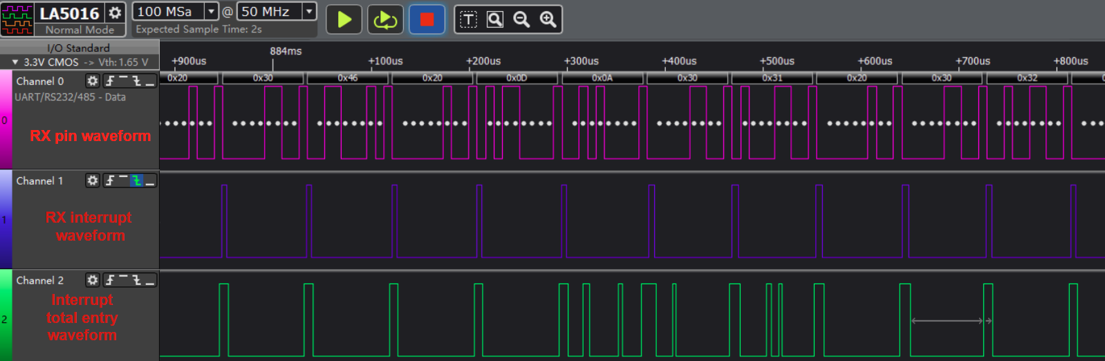
picture 7-2 UART no data loss
picture 7-3 UART data lossCalculation Method:
In the 8N1 protocol, there are 8 data bits, 1 stop bit, 1 start bit, and no parity bit. This means that communicating 1 byte of data requires a 10-bit width.
Baud Rate - Concept: The rate of serial communication, measured in bps (bits per second), which is the number of binary bits that can be transmitted per second.
For example, 115200 means that 115200 binary bits can be transmitted per second, or 115200 bits.
At a baud rate of 115200, with a 32-byte FIFO depth, the waiting time is calculated as follows:
time = (FIFO depth * bit width per byte) / baud rate

= (32 * 10) / (115200) s

= 2.78ms
Solution
If data loss occurs at a high UART baud rate, handling other interrupts may cause the UART RX interrupt to be blocked for too long, leading to data loss. In this case, enabling URDMA is necessary to ensure that data is not lost. Q3: Setting the baud rate greater than 1M in stty fails
Q3: Setting the baud rate greater than 1M in stty fails
-
Setting the baud rate greater than 1M using the stty command fails
/ # stty -F /dev/ttyS2 1000000 stty: invalid argument '1000000' -
Explanation
This is a problem with Busybox. Versions 1.26.x and later allow setting baud rates greater than 1M.
-
Solution
To set a baud rate greater than 1M, you can use the C program.
-