MI LDC API
REVISION HISTORY
| Revision No. | Description |
Date |
|---|---|---|
| 3.0 | 12/04/2020 | |
| 3.1 | 07/04/2021 | |
| 08/25/2021 | ||
| 3.2 | 05/10/2022 | |
| 4.0 | 06/13/2022 | |
| 11/15/2022 | ||
| 4.1 | 01/12/2023 | |
| 02/16/2023 | ||
| 03/15/2023 | ||
| 06/29/2023 | ||
| 08/09/2023 | ||
| 08/10/2023 | ||
| 09/05/2023 | ||
| 09/26/2023 | ||
| 11/21/2023 | ||
| 07/03/2024 | ||
| 08/22/2024 | ||
| 03/26/2024 | ||
| 04/09/2024 | ||
| 05/09/2024 | ||
| 06/19/2024 | ||
| 4.2 | 08/21/2024 | |
| 10/15/2024 | ||
| 4.3 | 02/24/2025 | |
| 4.4 | 04/03/2025 | |
| 06/03/2025 | ||
| 4.5 | 09/02/2025 | |
| 10/23/2025 | ||
| 4.6 | 11/13/2025 | |
| 11/13/2025 |
1. OVERVIEW
1.1. Module Description
MI_LDC is a computer vision module that currently supports Lens Distortion Correction, Perspective Rransformation, Perspective Mapping Function, Image Stitch, Blending, Digital Image Stabilization (DIS) and Lookup Table function (LUT).
Keyword
-
Device
MI_LDC corresponding hardware device
-
Channel
The MI_LDC module processes channels, and the hardware of each channel is time-sharing multiplexed.
1.2. Basic Structure
MI_LDC processes images differently based on the functions used.
-
LDC construct the output image.
-
DIS calculation shake.
-
BLEND processes image fusion.
The Digital Image Stabilization function requires DIS to completes the shake calculation first, and then LDC to completes the output image construction; The Blending function requires LDC to image stitching first, and then BLEND to completes the image fusion; The LDC will independently completes the output image construction for other functions.
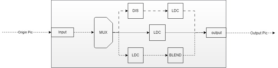
Generally, ISP is front module of MI_LDC, and SCL is back module of MI_LDC. If scaling is not required, the back module can be VENC.
1.3. Function Introduction
MI_LDC supported functions:
-
Lens distortion correction
According to lens calibration parameters, input image is subjected to distortion correction processing, and then output according to the projection mode and the region of interest configured by the user.
-
PMF
Perspective Mapping Function, use 3x3Matrix to deal with projection transformation task.
-
STITCH (Image stitching and fusion)
Distortion correction is performed on images come from multiple sensors, then multiple images are stitched together, and finally the overlapping areas of the images are fused.
-
DIS
Digital image stabilization, currently support gyroscope algorithm, GME algorithm stabilization and customized algorithm stabilization. The gyroscope algorithm calculates the motion offset of the current frame according to the data generated by the gyroscope, while the GME algorithm calculates the motion offset of the current frame according to the information of the previous frame, and then carries out translation, rotation and other transformations of the current image according to the motion offset, thus achieving the effect of anti-shaking.
-
NIR
Vis and Near infrared fusion scene, use for stitching of Vis and Near infrared, and the next step will be in the NIR module.
-
DPU
For Depth Process Unit, it will be a stitching pretreatment for dual sensor depth processing, and the next step will be in the DPU module.
-
Lookup table
Provides a two-dimensional lookup table function. The data bit width of the index and table in the x and y directions are both 8bit, which can be used for fast search of the weight table of the image fusion algorithm.
1.4. Application Scenarios
MI_LDC can be applied in the following scenarios, Some functions only support specific scenarios:
-
Pure linux environment
Applications can be developed based on the API interfaces provided by MI_LDC.
-
Pure rtos environment
In an RTOS environment, applications can be developed based on the API interfaces provided by MI_LDC.
Note: Image Stitch, Blending, and Digital Image Stabilization are not supported.
-
Dualos environment
In a dual OS environment, applications running on the Linux side and applications running on the RTOS side can both be developed based on the MI_LDC API.
Note: Image Stitch, Blending, and Digital Image Stabilization are not supported.
1.5. Chip Difference
- Note: Please refer to the relevant instructions for Iford in the current document.
'N' and '/' both indicate unsupported.
Note: iFord and Jaguar1 platform supports horizontal distortion correction(one-dimensional distortion correction), which is a function of Module ISP. For specific usage, please refer to MI ISP API.
-
Maximum number of channels for different functions supported by each platform, in framemode binding:
Function
PlatformLDC PMF DIS STITCH NIR DPU LUT Souffle 16 16 4 1 16 16 16 iFord 16 16 4 / / / / iFackel 16 16 4 1 / 16 / Jaguar1 16 16 4 / / / / Note: When not using framemode binding, it is limited to 1 channel
Different chips have hardware and functional differences:
-
E_MI_SYS_BIND_TYPE_REALTIME corresponds to the realtime binding Mode. MI_ISP and MI_LDC can be bound in this mode, which only supports STITCH function.
-
E_MI_SYS_BIND_TYPE_HW_AUTOSYNC corresponds to the low latency binding Mode. It requires MI_ISP, MI_LDC, and MI_SCL to be simultaneously bound in this mode, which only supports Lens Distortion Correction function.
-
Pixel Alignment (WxH) is hardware alignment requirements.
1.5.1. Souffle
| Function | Input Format | Output Format | Binding Mode | |||||||||||||||
| LDC | PMF | DIS | STITCH | NIR | DPU | LUT | yuv420SP NV12 | ARGB Series | Pixel Alignment (WxH) | yuv420SP NV12 | YUYV | ARGB Series | Pixel Alignment (WxH) | E_MI_SYS_BIND_TYPE_FRAME_BASE | E_MI_SYS_BIND_TYPE_REALTIME | E_MI_SYS_BIND_TYPE_HW_AUTOSYNC | ||
| DIS-GME | DIS-GYRO | DIS-CUST | ||||||||||||||||
| Y | Y | Y | Y | Y | Y | Y | Y | Y | Y | Y | 16x2 | Y | N | Y | 16x2 | Y | Y | Y |
Note: DIS function does not support ARGB input formats. STITCH function does not support YUYV and ARGB output formats.
DIS-GME Mode:

Note:
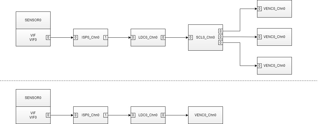
- When the DIS-GME mode does anti-shake processing, it needs to refer to the information of the previous frame. Therefore, the DIS Processs needs the four pictures information as shown in the above figure (the resolution of the previous frame and the current frame is 1080P and 120x68);
- When the DIS-GME mode is enabled on the LDC, the front-end module can only be bound to the SCL module, and its three Output ports can output the resolution images required in the above figure and send them to the three Input ports of the LDC;
- Currently the maximum original image resolution is 4K;
- Alignment Restriction: Since DIS is a sub-module of LDC, the input and output images must be aligned with each other by 16 pixels in width and 2 pixels in height. For example:
- If the previous level is bound to SCL, the size of the three input images such as: Origin Pictrue is aligned according to the above requirements; 1080P Pictrue meets the above requirements by default; 120x68 Pictrue width will automatically Stride to 128x68 due to MI_LDC internal forced alignment.
- If MI_SYS_ChnInputPortPutBuf is used to send traffic to the DIS, the three input images are as follows: Origin Pictrue is aligned according to the above requirements; 1080P Pictrue meets the above requirements by default; 120x68 Pictrue width needs to Stride to 128x68 before sending to the Input port2.
DIS-GYRO Mode:

Note:
-
DIS-GYRO mode requires current frame data and internal gyroscope data for anti-shake processing. Therefore, the DIS Process requires a picture information as shown in the figure above(the current frame).
-
When the DIS-GYRO mode is enabled on the LDC, there is no specific restriction on the previous module. For details about the image size, see the LDC restriction.
-
When the DIS-GYRO mode is enabled on the LDC, connection to the pipeline is necessary because some information needs to be obtained from the Sensor in real time to help the algorithm perform calculations.
DIS-CUST Mode:

-
When the DIS-CUST mode is used for anti-shake processing, the callback function pCalIsMatrixCb in user mode needs to be called. Therefore, the DIS Process requires a picture information as shown in the figure above(the current frame).
-
When the DIS-CUST mode is enabled on the LDC, there is no specific restriction on the previous module. For details about the image size, see the LDC restriction.
STITCH:

Note:
- The maximum width of blending is 1648, and the maximum height is 4224.
- After blending, only the blending image will be output by default, and no overlapping image will be included.
- Alignment restrictions: The width of the input image and the output image must be aligned at 16 pixels, and the height must be aligned at 2 pixels. If the configured sampling accuracy is greater than 16, the alignment requirement matches the sampling accuracy. For example, setting grid_size=32 requires the input image to be aligned at 32 pixels.
1.5.2. iFord
| Function | Input Format | Output Format | Binding Mode | |||||||||||||||
| LDC | PMF | DIS | STITCH | NIR | DPU | LUT | yuv420SP NV12 | ARGB Series | Pixel Alignment (WxH) | yuv420SP NV12 | YUYV | ARGB Series | Pixel Alignment (WxH) | E_MI_SYS_BIND_TYPE_FRAME_BASE | E_MI_SYS_BIND_TYPE_REALTIME | E_MI_SYS_BIND_TYPE_HW_AUTOSYNC | ||
| DIS-GME | DIS-GYRO | DIS-CUST | ||||||||||||||||
| Y | Y | N | Y | N | N | N | N | N | Y | N | 16x2 | Y | Y | N | 16x2 | Y | N | Y |
1.5.3. iFackel
| Function | Input Format | Output Format | Binding Mode | |||||||||||||||
| LDC | PMF | DIS | STITCH | NIR | DPU | LUT | yuv420SP NV12 | ARGB Series | Pixel Alignment (WxH) | yuv420SP NV12 | YUYV | ARGB Series | Pixel Alignment (WxH) | E_MI_SYS_BIND_TYPE_FRAME_BASE | E_MI_SYS_BIND_TYPE_REALTIME | E_MI_SYS_BIND_TYPE_HW_AUTOSYNC | ||
| DIS-GME | DIS-GYRO | DIS-CUST | ||||||||||||||||
| Y | Y | Y | Y | Y | Y | N | Y | N | Y | N | 16x2 | Y | Y | N | 16x2 | Y | N | Y |
Note: DIS function does not support ARGB input formats. STITCH function does not support YUYV and ARGB output formats.
DIS-GME Mode:
Note:
- When the DIS-GME mode does anti-shake processing, it needs to refer to the information of the previous frame. Therefore, the DIS Processs needs the four pictures information as shown in the above figure (the resolution of the previous frame and the current frame is 1080P and 120x68);
- When the DIS-GME mode is enabled on the LDC, the front-end module can only be bound to the SCL module, and its three Output ports can output the resolution images required in the above figure and send them to the three Input ports of the LDC;
- Currently the maximum original image resolution is 4K;
- Alignment Restriction: Since DIS is a sub-module of LDC, the input and output images must be aligned with each other by 16 pixels in width and 2 pixels in height. For example:
- If the previous level is bound to SCL, the size of the three input images such as: Origin Pictrue is aligned according to the above requirements; 1080P Pictrue meets the above requirements by default; 120x68 Pictrue width will automatically Stride to 128x68 due to MI_LDC internal forced alignment.
- If MI_SYS_ChnInputPortPutBuf is used to send traffic to the DIS, the three input images are as follows: Origin Pictrue is aligned according to the above requirements; 1080P Pictrue meets the above requirements by default; 120x68 Pictrue width needs to Stride to 128x68 before sending to the Input port2.
DIS-GYRO Mode:
Note:
-
DIS-GYRO mode requires current frame data and internal gyroscope data for anti-shake processing. Therefore, the DIS Process requires a picture information as shown in the figure above(the current frame).
-
When the DIS-GYRO mode is enabled on the LDC, there is no specific restriction on the previous module. For details about the image size, see the LDC restriction.
-
When the DIS-GYRO mode is enabled on the LDC, connection to the pipeline is necessary because some information needs to be obtained from the Sensor in real time to help the algorithm perform calculations.
DIS-CUST Mode:
-
When the DIS-CUST mode is used for anti-shake processing, the callback function pCalIsMatrixCb in user mode needs to be called. Therefore, the DIS Process requires a picture information as shown in the figure above(the current frame).
-
When the DIS-CUST mode is enabled on the LDC, there is no specific restriction on the previous module. For details about the image size, see the LDC restriction.
STITCH:
Note:
- The maximum width of blending is 1648, and the maximum height is 4224.
- After blending, only the blending image will be output by default, and no overlapping image will be included.
- Alignment restrictions: The width of the input image and the output image must be aligned at 16 pixels, and the height must be aligned at 2 pixels. If the configured sampling accuracy is greater than 16, the alignment requirement matches the sampling accuracy. For example, setting grid_size=32 requires the input image to be aligned at 32 pixels.
1.5.4. Jaguar1
| Function | Input Format | Output Format | Binding Mode | |||||||||||||||
| LDC | PMF | DIS | STITCH | NIR | DPU | LUT | yuv420SP NV12 | ARGB Series | Pixel Alignment (WxH) | yuv420SP NV12 | YUYV | ARGB Series | Pixel Alignment (WxH) | E_MI_SYS_BIND_TYPE_FRAME_BASE | E_MI_SYS_BIND_TYPE_REALTIME | E_MI_SYS_BIND_TYPE_HW_AUTOSYNC | ||
| DIS-GME | DIS-GYRO | DIS-CUST | ||||||||||||||||
| Y | Y | N | Y | N | N | N | N | N | Y | N | 16x2 | Y | Y | N | 16x2 | Y | N | Y |
1.6. Working Principle
NA
1.7. Development Process
1.7.1. Compile Configuration
-
Enter the project directory of alkaid, make menuconfig
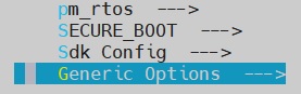
-
Press the enter key to select the "Generic Options" submenu
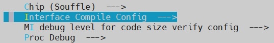
-
Press the Enter key again to enter the "Interface Compile Config" submenu
-
Use the spacebar to select the "ldc" submodule. Once selected, save your configuration and recompile the project
1.7.2 Interface Call
When using different functions, the overall interface call process is similar. However, there will be differences when setting parameters, as shown in the figure below.

The MI_LDC generic stream interface call is divided into the following steps:
-
MI_SYS initialize
-
Create MI_LDC Device
-
Create MI_LDC Channel
-
Set MI_LDC input port parameter
-
Set MI_LDC output port parameter
-
Based on the function used, call the corresponding channel parameter configuration interface.
-
Based on the scenario, the MI_SYS_BindChnPort2 interface may be called to bind preceding and succeeding modules
-
Start MI_LDC Channel
-
Call the MI_SYS_UnBindChnPort interface to unbind the preceding and succeeding stage modules
-
Stop MI_LDC Channel
-
Destroy MI_LDC Channel
-
Destroy MI_LDC Device
-
MI_SYS deinitialization
1.8. Examples
- This is Lens distortion correction function example.
    MI_U32                  LdcDevId = 0, LdcChnId = 0;
    MI_LDC_DevAttr_t        stCreateDevAttr     = {};
    MI_LDC_ChnAttr_t        stLdcChnAttr        = {};
    MI_LDC_OutputPortAttr_t stLdcOutputPortAttr = {};
    MI_LDC_InputPortAttr_t  stLdcInputPortAttr  = {};
    MI_LDC_ChnLDCAttr_t     stAttr              = {};

    MI_SYS_Init(0);
    MI_LDC_CreateDevice(LdcDevId, &stCreateDevAttr);

    stLdcChnAttr.eInputBindType = E_MI_SYS_BIND_TYPE_FRAME_BASE;
    stLdcChnAttr.eWorkMode      = MI_LDC_WORKMODE_LDC;
    MI_LDC_CreateChannel(LdcDevId, LdcChnId, &stLdcChnAttr);

    stLdcInputPortAttr.u16Width  = 1920;
    stLdcInputPortAttr.u16Height = 1080;
    MI_LDC_SetInputPortAttr(LdcDevId, LdcChnId, &stLdcInputPortAttr);

    stLdcOutputPortAttr.ePixelFmt = E_MI_SYS_PIXEL_FRAME_YUV_SEMIPLANAR_420;
    stLdcOutputPortAttr.u16Width  = 1920;
    stLdcOutputPortAttr.u16Height = 1080;
    MI_LDC_SetOutputPortAttr(LdcDevId, LdcChnId, &stLdcOutputPortAttr);

    stAttr.u32RegionNum                        = 1;
    stAttr.eMountMode                          = MI_LDC_WALL_MOUNT;
    stAttr.stRegionAttr[0].eRegionMode         = MI_LDC_REGION_NO_TRANSFORMATION; // This mode performs no correction and outputs the original image
    stAttr.stRegionAttr[0].stOutRect.u16X      = 0;
    stAttr.stRegionAttr[0].stOutRect.u16Y      = 0;
    stAttr.stRegionAttr[0].stOutRect.u16Width  = 1920;
    stAttr.stRegionAttr[0].stOutRect.u16Height = 1080;
    stAttr.stCalibInfo.pCalibPolyBinAddr       = NULL; // Replace with the address of lens calibration output CalibPoly_new.bin
    stAttr.stCalibInfo.u32CalibPolyBinSize     = 0;    // Replace with the byte count of lens calibration output CalibPoly_new.bin
    MI_LDC_SetChnLDCAttr(LdcDevId, LdcChnId, &stAttr);

    // Bind the front and back modules. Please complete based on your scenario by yourself

    MI_LDC_StartChannel(LdcDevId, LdcChnId);

    // Unbind the front and back modules. Please complete based on your scenario by yourself

    MI_LDC_StopChannel(LdcDevId, LdcChnId);
    MI_LDC_DestroyChannel(LdcDevId, LdcChnId);
    MI_LDC_DestroyDevice(LdcDevId);
    MI_SYS_Exit(0);
- This is Image Stitch and Blending function example.
    MI_U32                  LdcDevId = 0, LdcChnId = 0;
    MI_LDC_DevAttr_t        stCreateDevAttr     = {};
    MI_LDC_ChnAttr_t        stLdcChnAttr        = {};
    MI_LDC_OutputPortAttr_t stLdcOutputPortAttr = {};
    MI_LDC_InputPortAttr_t  stLdcInputPortAttr  = {};
    MI_LDC_ChnStitchAttr_t  stAttr              = {};

    MI_SYS_Init(0);
    MI_LDC_CreateDevice(LdcDevId, &stCreateDevAttr);

    stLdcChnAttr.eInputBindType = E_MI_SYS_BIND_TYPE_FRAME_BASE;
    stLdcChnAttr.eWorkMode      = MI_LDC_WORKMODE_LDC;
    MI_LDC_CreateChannel(LdcDevId, LdcChnId, &stLdcChnAttr);

    stLdcInputPortAttr.u16Width  = 3840; // Width of single sensor output
    stLdcInputPortAttr.u16Height = 2160; // Height of single sensor output
    MI_LDC_SetInputPortAttr(LdcDevId, LdcChnId, &stLdcInputPortAttr);

    stLdcOutputPortAttr.ePixelFmt = E_MI_SYS_PIXEL_FRAME_YUV_SEMIPLANAR_420;
    stLdcOutputPortAttr.u16Width  = 6160; // Width of the stitched and blending image
    stLdcOutputPortAttr.u16Height = 1984; // Height of the stitched and blending image
    MI_LDC_SetOutputPortAttr(LdcDevId, LdcChnId, &stLdcOutputPortAttr);

    stAttr.eProjType                = MI_LDC_PROJECTION_SPHERICAL;
    stAttr.s32Distance              = 5000;
    stAttr.stCalCfg.pCalibCfgAddr   = NULL; // Replace with the address of calibration output calib_out.json
    stAttr.stCalCfg.u32CalibCfgSize = 0; // Replace with the byte count of calibration output calib_out.json
    MI_LDC_SetChnStitchAttr(LdcDevId, LdcChnId, &stAttr);

    // Bind the front and back modules. Please complete based on your scenario by yourself

    MI_LDC_StartChannel(LdcDevId, LdcChnId);

    // Unbind the front and back modules. Please complete based on your scenario by yourself

    MI_LDC_StopChannel(LdcDevId, LdcChnId);
    MI_LDC_DestroyChannel(LdcDevId, LdcChnId);
    MI_LDC_DestroyDevice(LdcDevId);
    MI_SYS_Exit(0);
2. API LIST
This module provides the following APIs:
| API Name | Function |
|---|---|
| MI_LDC_CreateDevice | Create an LDC device |
| MI_LDC_DestroyDevice | Destroy an LDC device |
| MI_LDC_CreateChannel | Create an LDC channel |
| MI_LDC_DestroyChannel | Destroy an LDC channel |
| MI_LDC_StartChannel | Start an LDC channel |
| MI_LDC_StopChannel | Stop an LDC channel |
| MI_LDC_SetChnLDCAttr | Configure LDC mode channel attribute |
| MI_LDC_GetChnLDCAttr | Get LDC mode channel attribute |
| MI_LDC_SetChnDISAttr | Configure DIS mode channel attribute |
| MI_LDC_GetChnDISAttr | Get DIS mode channel attribute |
| MI_LDC_SetChnPMFAttr | Configure PMF mode channel attribute |
| MI_LDC_GetChnPMFAttr | Get PMF mode channel attribute |
| MI_LDC_SetChnStitchAttr | Configure Stitch mode channel attribute |
| MI_LDC_GetChnStitchAttr | Get Stitch mode channel attribute |
| MI_LDC_SetChnDPUAttr | Configure DPU mode channel attribute |
| MI_LDC_GetChnDPUAttr | Get DPU mode channel attribute |
| MI_LDC_SetChnNIRAttr | Configure NIR mode channel attribute |
| MI_LDC_GetChnNIRAttr | Get NIR mode channel attribute |
| MI_LDC_SetInputPortAttr | Configure LDC input port attribute |
| MI_LDC_GetInputPortAttr | Get LDC input port attribute |
| MI_LDC_SetOutputPortAttr | Configure LDC output port attribute |
| MI_LDC_GetOutputPortAttr | Get LDC output port attribute |
| MI_LDC_DoLutDirectTask | Execute table lookup tasks, send buffer directly to ldc hardware for processing |
| MI_LDC_GetRegionBorderMappedPointCnt | Get the point count of mapped border to be drew |
| MI_LDC_GetRegionBorderMappedPoints | Get the coordinate of mapped border to be drew |
| MI_LDC_GetDisplacementMapSize | Get the size of displacement map in the coordinate query function |
| MI_LDC_GenerateDisplacementMap | Generate displacement map in the coordinate query function |
| MI_LDC_QueryMappingPoint | Query mapped coordinates of target point |
| MI_LDC_QueryMappingPoints | Query multiple mapping coordinates simultaneously |
| MI_LDC_CalibIMUBaseDrift | Calibrate the sensor |
| MI_LDC_SetIMUDriftPara | Set the calibration data to calibrate the sensor |
| MI_LDC_GetIMUDriftPara | Get the calibration data of the sensor |
| MI_LDC_GetDisAuxiliaryInfo | Get some auxiliary data about DIS |
2.1. MI_LDC_CreateDevice
-
Description
Create an LDC device
-
Syntax
MI_S32 MI_LDC_CreateDevice(MI_LDC_DEV devId, MI_LDC_DevAttr_t *pstDevAttr); -
Parameters
Parameter Name Description Input/Output devId Device ID number Input pstDevAttr eWorkMdoe Device working mode attribute Input -
Return Value
-
Zero: Successful
-
Non-zero: Failed, see ERROR CODE for details.
-
-
Dependence
-
Header file: mi_ldc.h
-
Lib: libmi_ldc.a
-
-
Note
Currently only devId = 0 is supported.
-
Example
LDC initialization settings and exit example:
MI_S32 s32Ret = MI_SUCCESS; MI_LDC_DEV LdcDevid = 0; MI_LDC_CHN LdcChnId = 0; MI_LDC_DevAttr_t stDevAttr = {}; MI_LDC_ChnAttr_t stChnAttr = {}; MI_LDC_ChnLDCAttr_t stChnLDCAttr = {}; stChnAttr.eMode = MI_LDC_WORKMODE_LDC ; stChnAttr.eInputBindType = E_MI_SYS_BIND_TYPE_FRAME_BASE; MI_LDC_CreateDevice(LdcDevid, & stDevAttr); MI_LDC_CreateChannel(LdcDevid, LdcChnId, &stChnAttr); // We should call corresponding function according to channel workmode // For more detailed config, please refer to interface description // The following interface calls are in no particular order: // 1. MI_LDC_SetInputPortAttr // 2. MI_LDC_SetChnLDCAttr // 3. MI_LDC_SetOutputPortAttr MI_LDC_StartChannel(LdcDevid, LdcChnId); /*Destroy channel*/ MI_LDC_StopChannel(LdcDevid, LdcChnId); MI_LDC_DestroyChannel(LdcDevid, LdcChnId); MI_LDC_DestroyDevice(LdcDevid); -
Related APIs
2.2. MI_LDC_DestroyDevice
-
Description
Destroy an LDC device
-
Syntax
MI_S32 MI_LDC_DestroyDevice(MI_LDC_DEV devId); -
Parameters
Parameter Name Description Input/Output devId Device ID number Input -
Return Value
-
Zero: Successful
-
Non-zero: Failed, see ERROR CODE for details.
-
-
Dependence
-
Header file: mi_ldc.h
-
Lib: libmi_ldc.a
-
-
Note
Currently only devId = 0 is supported.
-
Example
Refer to MI_LDC_CreateDevice example.
-
Related APIs
2.3. MI_LDC_CreateChannel
-
Description
Create an LDC channel
-
Syntax
MI_S32 MI_LDC_CreateChannel(MI_LDC_DEV devId, MI_LDC_CHN chnId, MI_LDC_ChnAttr_t *pstChnAttr); -
Parameters
Parameter Name Description Input/Output devId Device ID number Input chnId LDC Channel number Input -
Return Value
-
Zero: Successful
-
Non-zero: Failed, see ERROR CODE for details.
-
-
Dependence
-
Header file: mi_ldc.h
-
Lib: libmi_ldc.a
-
-
Note
-
This API needs to be called after MI_LDC_CreateDevice.
-
When channel is created, the mode of channel will be changeless until channel is destroy. During this period, we can only use the interface configuration parameters of the corresponding mode.
-
-
Example
Refer to MI_LDC_CreateDevice example.
-
Related APIs
2.4. MI_LDC_DestroyChannel
-
Description
Destroy an LDC channel
-
Syntax
MI_S32 MI_LDC_DestroyChannel(MI_LDC_DEV devId, MI_LDC_CHN chnId); -
Parameters
Parameter Name Description Input/Output devId Device ID number Input chnId LDC Channel number Input -
Return Value
-
Zero: Successful
-
Non-zero: Failed, see ERROR CODE for details.
-
-
Dependence
-
Header file: mi_ldc.h
-
Lib: libmi_ldc.a
-
-
Example
Refer to MI_LDC_CreateDevice example.
-
Related APIs
2.5. MI_LDC_StartChannel
-
Description
Start an LDC channel.
-
Syntax
MI_S32 MI_LDC_StartChannel(MI_LDC_DEV devId, MI_LDC_CHN chnId); -
Parameters
Parameter Name Description Input/Output devId Device ID number Input chnId LDC Channel number Input -
Return Value
-
Zero: Successful
-
Non-zero: Failed, see ERROR CODE for details.
-
-
Dependence
-
Header file: mi_ldc.h
-
Lib: libmi_ldc.a
-
-
Note
Call this API after Device and Channel have been created.
-
Example
Refer to MI_LDC_CreateDevice example.
-
Related APIs
2.6. MI_LDC_StopChannel
-
Description
Stop an LDC channel.
-
Syntax
MI_S32 MI_LDC_StopChannel(MI_LDC_DEV devId, MI_LDC_CHN chnId); -
Parameters
Parameter Name Description Input/Output devId Device ID number Input chnId LDC Channel number Input -
Return Value
-
Zero: Successful
-
Non-zero: Failed, see ERROR CODE for details.
-
-
Dependence
-
Header file: mi_ldc.h
-
Lib: libmi_ldc.a
-
-
Example
Refer to MI_LDC_CreateDevice example.
-
Related APIs
2.7. MI_LDC_SetChnLDCAttr
-
Description
Configure LDC mode channel attribute.
-
Syntax
MI_S32 MI_LDC_SetChnLDCAttr(MI_LDC_DEV devId, MI_LDC_CHN chnId, MI_LDC_ChnLDCAttr_t *pstChnLDCAttr); -
Parameters
Parameter Name Description Input/Output devId Device ID number Input chnId LDC Channel number Input pstChnLDCAttr LDC Channel attribute Input -
Return Value
-
Zero: Successful
-
Non-zero: Failed, see ERROR CODE for details.
-
-
Dependence
-
Header file: mi_ldc.h
-
Lib: libmi_ldc.a
-
-
Note
You can obtain the information through this interface after Create Channel.
-
Example
Refer to MI_LDC_CreateDevice example.
2.8. MI_LDC_GetChnLDCAttr
-
Description
Get LDC mode channel attribute.
-
Syntax
MI_S32 MI_LDC_GetChnLDCAttr(MI_LDC_DEV devId, MI_LDC_CHN chnId, MI_LDC_ChnLDCAttr_t *pstChnLDCAttr); -
Parameters
Parameter Name Description Input/Output devId Device ID number Input chnId LDC Channel number Input pstChnLDCAttr LDC Channel attribute Output -
Return Value
-
Zero: Successful
-
Non-zero: Failed, see ERROR CODE for details.
-
-
Dependence
-
Header file: mi_ldc.h
-
Lib: libmi_ldc.a
-
-
Note
You can obtain the information through this interface after Create Channel.
-
Example
Refer to MI_LDC_CreateDevice example.
2.9. MI_LDC_SetChnDISAttr
-
Description
Configure DIS mode channel attribute.
-
Syntax
MI_S32 MI_LDC_SetChnDISAttr(MI_LDC_DEV devId, MI_LDC_CHN chnId, MI_LDC_ChnDISAttr_t *pstChnDISAttr); -
Parameters
Parameter Name Description Input/Output devId Device ID number Input chnId LDC Channel number Input pstChnDISAttr DIS Channel attribute Input -
Return Value
-
Zero: Successful
-
Non-zero: Failed, see ERROR CODE for details.
-
-
Dependence
-
Header file: mi_ldc.h
-
Lib: libmi_ldc.a
-
-
Note
You can obtain the information through this interface after Create Channel.
-
Example
LDC, DIS initialization settings and exit example:
For Iford Platform:
MI_S32 s32Ret = MI_SUCCESS;
MI_LDC_DEV LdcDevid = 0;
MI_LDC_CHN LdcChnId = 0;
MI_LDC_DevAttr_t stDevAttr = {};
MI_LDC_ChnAttr_t stChnAttr = {};
MI_LDC_ChnDISAttr_t stChnDISAttr = {};
MI_LDC_IMUDrift_t   stIMUDrift = {};
MI_LDC_DisAuxiliaryInfo_t  stAuxInfo = {};

#if defined(__USE_DIS_GYRO_MODE__)

stChnAttr.eMode = MI_LDC_WORKMODE_DIS ;
stChnAttr.eInputBindType = E_MI_SYS_BIND_TYPE_FRAME_BASE;

MI_LDC_CreateDevice(LdcDevid, & stDevAttr);
MI_LDC_CreateChannel(LdcDevid, LdcChnId, &stChnAttr);

stChnDISAttr.eMode = MI_LDC_DIS_GYRO;
stChnDISAttr.as32RotationMatrix[LDC_MAXTRIX_NUM] = {-1, 0, 0, 0, -1, 0, 0, 0, -1};
stChnDISAttr.u32UserSliceNum = 6;

/*!
 * set FocalLengh (pixel) = FocalLength(mm) / SensorUnitCellSize(μm) * 1000 * 100
 *  eg IMX307: 5.92(pixel) / 2.9(μm) * 1000 * 100 = 204137
 *  eg IMX317: 6(pixel) / 1.62(μm) * 1000*100 = 370370
 */
stChnDISAttr.u32FocalLengthX = 370370;
stChnDISAttr.u32FocalLengthY = 370370;

// The configuration details are ignored here. For details, see Interface description.
// The corresponding interface needs to be configured according to the channel mode. The following interface calls are in no particular order.
// 1. MI_LDC_SetChnDISAttr
// 2. MI_LDC_GetChnDISAttr
// 3. MI_LDC_SetOutputPortAttr
// MI_LDC_DIS_GYRO mode requires data to be obtained from the Sensor in real time to help the algorithm perform calculations, so the pipeline should be connected to work properly.

#elif defined(__USE_DIS_GYRO_AND_LDC_MODE__)

stChnAttr.eMode = MI_LDC_WORKMODE_DIS_LDC;
stChnAttr.eInputBindType = E_MI_SYS_BIND_TYPE_FRAME_BASE;

MI_LDC_CreateDevice(LdcDevid, & stDevAttr);
MI_LDC_CreateChannel(LdcDevid, LdcChnId, &stChnAttr);

stChnDISAttr.eMode = MI_LDC_DIS_GYRO;
stChnDISAttr.as32RotationMatrix[LDC_MAXTRIX_NUM] = {0, 1, 0, -1, 0, 0, 0, 0, 1};
stChnDISAttr.u32UserSliceNum = 6;

/*!
 * set FocalLengh (pixel) = FocalLength(mm) / SensorUnitCellSize(um) * 1000 * 100
 *  eg IMX307: 5.92(pixel) / 2.9(um) * 1000 * 100 = 204137
 *  eg IMX317: 6(pixel) / 1.62(um) * 1000*100 = 370370
 */
stChnDISAttr.u32FocalLengthX = 370370;
stChnDISAttr.u32FocalLengthY = 370370;

/*!
 * Only the sensor calibration parameters MI_LDC_SensorCalibInfo_t and
 * the s32DistortionRatio of the first stRegionAttr need to be populated.
 * Other parameters can be left empty.
 */
MI_LDC_ChnLDCAttr_t stChnLDCAttr = {};
stChnLDCAttr.stCalibInfo.s32CenterXOffset = 0;
stChnLDCAttr.stCalibInfo.s32CenterYOffset = 0;
stChnLDCAttr.stCalibInfo.s32FisheyeRadius =2203;
stChnLDCAttr.stCalibInfo.pCalibPolyBinAddr = 0x400080000;
stChnLDCAttr.stCalibInfo.u32CalibPolyBinSize = 0x4000;
stChnLDCAttr.u32RegionNum = 1;
stChnLDCAttr.stRegionAttr[0].stRegionPara.s32DistortionRatio = 0;

// The configuration details are ignored here. For details, see Interface description.
// The corresponding interface needs to be configured according to the channel mode. The following interface calls are in no particular order.
// The following interface calls must first call MI_LDC_SetChnLDCAttr to set the lens calibration product, and then call MI_LDC_SetChnDISAttr to set the anti-shake related parameters.
// 1. MI_LDC_SetChnLDCAttr
// 2. MI_LDC_GetChnLDCAttr
// 3. MI_LDC_SetChnDISAttr
// 4. MI_LDC_GetChnDISAttr
// MI_LDC_DIS_GYRO mode requires data to be obtained from the Sensor in real time to help the algorithm perform calculations, so the pipeline should be connected to work properly.

#elif defined(__USE_DIS_CUST_MODE__)

stChnAttr.eMode = MI_LDC_WORKMODE_DIS ;
stChnAttr.eInputBindType = E_MI_SYS_BIND_TYPE_FRAME_BASE;

MI_LDC_CreateDevice(LdcDevid, & stDevAttr);
MI_LDC_CreateChannel(LdcDevid, LdcChnId, &stChnAttr);

/*
    MI_S32 CustCalIsMatrix(const MI_LDC_IsMatrixInParam_t * const pstInParam,  MI_LDC_IsMatrixOutParam_t * const pstOutParam)
    {
        MI_S32 s32Matrix[LDC_MAXTRIX_NUM] = {0x4000, 0, 0, 0, 0x4000, 0, 0, 0, 0x1};

        if (pstInParam == NULL || pstOutParam == NULL)
        {
            ldc_err("attr is null, pstInParam[%px], pstOutParam[%px]", pstInParam,pstOutParam);
            return -1;
        }

        memcpy(pstOutParam->as32Matrix, s32Matrix, sizeof(s32Matrix));

        return MI_SUCCESS;
    }
*/
stChnDISAttr.eMode = MI_LDC_DIS_CUST;
stChnDISAttr.pCalIsMatrixCb = CustCalIsMatrix;

// Ignore the specific configuration details here, see the interface description for detailed parameters
// Use the corresponding interface to configure according to the channel mode. The following interface calls are in no particular order.
// 1. MI_LDC_SetChnDISAttr
// 2. MI_LDC_GetChnDISAttr
// 3. MI_LDC_SetOutputPortAttr

#endif

MI_LDC_StartChannel(LdcDevid, LdcChnId);

// The following interface is only valid in MI_LDC_DIS_GYRO mode and needs to call MI_LDC_StartChannel first
// 1.MI_LDC_CalibIMUBaseDrift
// 2.MI_LDC_SetIMUDriftPara
// 3.MI_LDC_GetIMUDriftPara
// 4.MI_LDC_GetDisAuxiliaryInfo
MI_LDC_CalibIMUBaseDrift(LdcDevid, LdcChnId, E_MI_LDC_IMU_PART_GYRO, 10*1000);
// Wait 10*1000ms for calibration to complete
sleep(10);
MI_LDC_GetIMUDriftPara(LdcDevid, LdcChnId, &stIMUDrift);
MI_LDC_SetIMUDriftPara(LdcDevid, LdcChnId, &stIMUDrift);
MI_LDC_GetDisAuxiliaryInfo(LdcDevid, LdcChnId, &stAuxInfo);

/* Exit process */
MI_LDC_StopChannel(LdcDevid, LdcChnId);
MI_LDC_DestroyChannel(LdcDevid, LdcChnId);
MI_LDC_DestroyDevice(LdcDevid);
2.10. MI_LDC_GetChnDISAttr
-
Description
Get DIS mode channel attribute.
-
Syntax
MI_S32 MI_LDC_GetChnDISAttr(MI_LDC_DEV devId, MI_LDC_CHN chnId, MI_LDC_ChnDISAttr_t *pstChnDISAttr); -
Parameters
Parameter Name Description Input/Output devId Device ID number Input chnId LDC Channel number Input pstChnDISAttr DIS Channel attribute Output -
Return Value
-
Zero: Successful
-
Non-zero: Failed, see ERROR CODE for details.
-
-
Dependence
-
Header file: mi_ldc.h
-
Lib: libmi_ldc.a
-
-
Note
You can obtain the information through this interface after Create Channel.
-
Example
Refer to MI_LDC_SetChnDISAttr example.
2.11. MI_LDC_SetChnPMFAttr
-
Description
Configure PMF mode channel attribute.
-
Syntax
MI_S32 MI_LDC_SetChnPMFAttr(MI_LDC_DEV devId, MI_LDC_CHN chnId, MI_LDC_ChnPMFAttr_t *pstChnPMFAttr); -
Parameters
Parameter Name Description Input/Output devId Device ID number Input chnId LDC Channel number Input pstChnPMFAttr PMF Channel attribute Input -
Return Value
-
Zero: Successful
-
Non-zero: Failed, see ERROR CODE for details.
-
-
Dependence
-
Header file: mi_ldc.h
-
Lib: libmi_ldc.a
-
-
Note
You can obtain the information through this interface after Create Channel.
-
Example
Refer to MI_LDC_CreateDevice example.
2.12. MI_LDC_GetChnPMFAttr
-
Description
Get PMF mode channel attribute.
-
Syntax
MI_S32 MI_LDC_GetChnPMFAttr(MI_LDC_DEV devId, MI_LDC_CHN chnId, MI_LDC_ChnPMFAttr_t *pstChnPMFAttr); -
Parameters
Parameter Name Description Input/Output devId Device ID number Input chnId LDC Channel number Input pstChnPMFAttr PMF Channel attribute Output -
Return Value
-
Zero: Successful
-
Non-zero: Failed, see ERROR CODE for details.
-
-
Dependence
-
Header file: mi_ldc.h
-
Lib: libmi_ldc.a
-
-
Note
You can obtain the information through this interface after Create Channel.
-
Example
Refer to MI_LDC_CreateDevice example.
2.13. MI_LDC_SetChnStitchAttr
-
Description
Configure Stitch mode channel attribute.
-
Syntax
MI_S32 MI_LDC_SetChnStitchAttr(MI_LDC_DEV devId, MI_LDC_CHN chnId, MI_LDC_ChnStitchAttr_t *pstChnStitchAttr); -
Parameters
Parameter Name Description Input/Output devId Device ID number Input chnId LDC Channel number Input pstChnStitchAttr Stitch Channel attribute Input -
Return Value
-
Zero: Successful
-
Non-zero: Failed, see ERROR CODE for details.
-
-
Dependence
-
Header file: mi_ldc.h
-
Lib: libmi_ldc.a
-
-
Note
You can obtain the information through this interface after Create Channel.
-
Example
Refer to MI_LDC_CreateDevice example.
2.14. MI_LDC_GetChnStitchAttr
-
Description
Get Stitch mode channel attribute.
-
Syntax
MI_S32 MI_LDC_GetChnStitchAttr(MI_LDC_DEV devId, MI_LDC_CHN chnId, MI_LDC_ChnStitchAttr_t *pstChnStitchAttr); -
Parameters
Parameter Name Description Input/Output devId Device ID number Input chnId LDC Channel number Input pstChnStitchAttr Stitch Channel attribute Output -
Return Value
-
Zero: Successful
-
Non-zero: Failed, see ERROR CODE for details.
-
-
Dependence
-
Header file: mi_ldc.h
-
Lib: libmi_ldc.a
-
-
Note
You can obtain the information through this interface after Create Channel.
-
Example
Refer to MI_LDC_CreateDevice example.
2.15. MI_LDC_SetChnDPUAttr
-
Description
Configure DPU mode channel attribute.
-
Syntax
MI_S32 MI_LDC_SetChnDPUAttr(MI_LDC_DEV devId, MI_LDC_CHN chnId, MI_LDC_ChnDPUAttr_t *pstChnDPUAttr); -
Parameters
Parameter Name Description Input/Output devId Device ID number Input chnId LDC Channel number Input pstChnDPUAttr DPU Channel attribute Input -
Return Value
-
Zero: Successful
-
Non-zero: Failed, see ERROR CODE for details.
-
-
Dependence
-
Header file: mi_ldc.h
-
Lib: libmi_ldc.a
-
-
Note
You can obtain the information through this interface after Create Channel.
-
Example
Refer to MI_LDC_CreateDevice example.
2.16. MI_LDC_GetChnDPUAttr
-
Description
Get DPU mode channel attribute.
-
Syntax
MI_S32 MI_LDC_GetChnDPUAttr(MI_LDC_DEV devId, MI_LDC_CHN chnId, MI_LDC_ChnDPUAttr_t *pstChnDPUAttr); -
Parameters
Parameter Name Description Input/Output devId Device ID number Input chnId LDC Channel number Input pstChnDPUAttr DPU Channel attribute Output -
Return Value
-
Zero: Successful
-
Non-zero: Failed, see ERROR CODE for details.
-
-
Dependence
-
Header file: mi_ldc.h
-
Lib: libmi_ldc.a
-
-
Note
You can obtain the information through this interface after Create Channel.
-
Example
Refer to MI_LDC_CreateDevice example.
2.17. MI_LDC_SetChnNIRAttr
-
Description
Configure NIR mode channel attribute.
-
Syntax
MI_S32 MI_LDC_SetChnNIRAttr(MI_LDC_DEV devId, MI_LDC_CHN chnId, MI_LDC_ChnNIRAttr_t *pstChnNIRAttr); -
Parameters
Parameter Name Description Input/Output devId Device ID number Input chnId LDC Channel number Input pstChnNIRAttr NIR Channel attribute Input -
Return Value
-
Zero: Successful
-
Non-zero: Failed, see ERROR CODE for details.
-
-
Dependence
-
Header file: mi_ldc.h
-
Lib: libmi_ldc.a
-
-
Note
You can obtain the information through this interface after Create Channel.
-
Example
Refer to MI_LDC_CreateDevice example.
2.18. MI_LDC_GetChnNIRAttr
-
Description
Get NIR mode channel attribute.
-
Syntax
MI_S32 MI_LDC_GetChnNIRAttr(MI_LDC_DEV devId, MI_LDC_CHN chnId, MI_LDC_ChnNIRAttr_t *pstChnNIRAttr); -
Parameters
Parameter Name Description Input/Output devId Device ID number Input chnId LDC Channel number Input pstChnNIRAttr NIR Channel attribute Output -
Return Value
-
Zero: Successful
-
Non-zero: Failed, see ERROR CODE for details.
-
-
Dependence
-
Header file: mi_ldc.h
-
Lib: libmi_ldc.a
-
-
Note
You can obtain the information through this interface after Create Channel.
-
Example
Refer to MI_LDC_CreateDevice example.
2.19. MI_LDC_SetInputPortAttr
-
Description
Configure the LDC Input attribute.
-
Syntax
MI_S32 MI_LDC_SetInputPortAttr(MI_LDC_DEV devId, MI_LDC_CHN chnId, MI_LDC_InputPortAttr_t *pstInputAttr); -
Parameters
Parameter Name Description Input/Output devId Device ID number Input chnId LDC Channel number Input pstInputAttr Input attribute Input -
Return Value
-
Zero: Successful
-
Non-zero: Failed, see ERROR CODE for details.
-
-
Dependence
-
Header file: mi_ldc.h
-
Lib: libmi_ldc.a
-
-
Note
-
You can obtain the information through this interface after Create Channel.
-
After the first successful call to this interface, parameter 'pstInputAttr' is locked. All subsequent calls must use the same parameter values. If other parameter values are used, an error code will be returned and an error log will be printed. if you need to modify the parameter values, please recreate the channel before calling this interface again.
-
-
Example
Refer to MI_LDC_CreateDevice example.
2.20. MI_LDC_GetInputPortAttr
-
Description
Get the LDC Input attribute.
-
Syntax
MI_S32 MI_LDC_GetInputPortAttr(MI_LDC_DEV devId, MI_LDC_CHN chnId, MI_LDC_InputPortAttr_t *pstInputAttr); -
Parameters
Parameter Name Description Input/Output devId Device ID number Input chnId LDC Channel number Input pstInputAttr Input attribute Output -
Return Value
-
Zero: Successful
-
Non-zero: Failed, see ERROR CODE for details.
-
-
Dependence
-
Header file: mi_ldc.h
-
Lib: libmi_ldc.a
-
-
Note
You can obtain the information through this interface after Create Channel.
-
Example
Refer to MI_LDC_CreateDevice example.
2.21. MI_LDC_SetOutputPortAttr
-
Description
Configure the LDC output attribute.
-
Syntax
MI_S32 MI_LDC_SetOutputPortAttr(MI_LDC_DEV devId, MI_LDC_CHN chnId, MI_LDC_OutputPortAttr_t *pstOutputAttr); -
Parameters
Parameter Name Description Input/Output devId Device ID number Input chnId LDC Channel number Input pstOutputAttr Output attribute Input -
Return Value
-
Zero: Successful
-
Non-zero: Failed, see ERROR CODE for details.
-
-
Dependence
-
Header file: mi_ldc.h
-
Lib: libmi_ldc.a
-
-
Note
-
You can obtain the information through this interface after Create Channel.
-
Supported pixel format: NV12, ARGB8888, BGRA8888.
-
After the first successful call to this interface, parameter 'pstOutputAttr' is locked. All subsequent calls must use the same parameter values. If other parameter values are used, an error code will be returned and an error log will be printed. if you need to modify the parameter values, please recreate the channel before calling this interface again.
-
-
Example
MI_LDC_DEV devId = 0;
MI_LDC_CHN chnId = 0;
MI_LDC_OutputPortAttr_t  stLdcPortAttr = {};

MI_LDC_GetOutputPortAttr(devId, chnId, &stLdcPortAttr);
stLdcPortAttr.ePixelFmt = E_MI_SYS_PIXEL_FRAME_ARGB8888;
MI_LDC_SetOutputPortAttr(devId, chnId, &stLdcPortAttr);
2.22. MI_LDC_GetOutputPortAttr
-
Description
Get the LDC output attribute.
-
Syntax
MI_S32 MI_LDC_GetOutputPortAttr(MI_LDC_DEV devId, MI_LDC_CHN chnId, MI_LDC_OutputPortAttr_t *pstOutputAttr); -
Parameters
Parameter Name Description Input/Output devId Device ID number Input chnId LDC Channel number Input pstOutputAttr Output attribute Output -
Return Value
-
Zero: Successful
-
Non-zero: Failed, see ERROR CODE for details.
-
-
Dependence
-
Header file: mi_ldc.h
-
Lib: libmi_ldc.a
-
-
Note
You can obtain the information through this interface after Create Channel.
-
Example
Refer to MI_LDC_CreateDevice example.
2.23. MI_LDC_DoLutDirectTask
-
Description
Execute table lookup tasks, send buffer directly to ldc hardware for processing.
-
Syntax
MI_S32 MI_LDC_DoLutDirectTask(MI_LDC_DEV devID, MI_LDC_CHN chnId, MI_LDC_LutTaskAttr_t *pstAttr); -
Parameters
Parameter Name Description Input/Output devID Device initialization parameters Input pstAttr Table looking-up task configuration attribute Input/Output -
Return Value
-
Zero: Successful
-
None-zero: Failed, see ERROR CODE for details.
-
-
Dependence
-
Header: mi_ldc.h
-
Lib: libmi_ldc.a
-
-
Example
MI_S32 s32Ret = MI_SUCCESS;
MI_LDC_DEV devId = 0;
MI_LDC_CHN chnId = 0;
MI_LDC_LutTaskAttr_t  stLutTask = {};
MI_LDC_DirectBuf_t stTableX = {}, stTableY = {}, stTableWeight = {};
void *pVirTableX = NULL, *pVirTableY=NULL, *pVirTableWeight = NULL;

#define LUT_TABLE_Init(path, table, ppVir, w, h, __exit_func__)
do { \
table.ePixelFormat = E_MI_SYS_PIXEL_FRAME_I8; \
table.u32Width = w; \
table.u32Height = h; \
table.u32Stride[0] = w; \

    s32Ret = MI_SYS_MMa_Alloc(0, NULL, w*h, &table.phyAddr[0]); \
    if (s32Ret)
    {
        printf(“failed to malloc buf\n”);
        goto __exit_func__;
}
s32Ret = MI_SYS_Mmap(table.phyAddr[0], w*h, ppVir, false); \
if (s32Ret)
{
    printf(“failed to Mmap buf\n”);
    goto __exit_func__;
}
s32Ret = ReadBufFromFile(path, ppVir, w*h);
if (s32Ret)
{
    goto __exit_func__;
}
} while(0)

#define LUT_TABLE_Deinit(table, pVir)
do { \
    if (pVir)
    {
    MI_SYS_Munmap(pVir, table.u32Width * table.u32Height);
}
if (table.phyAddr[0])
{
    MI_SYS_MMA_Free(0, table.phyAddr[0]);
}
} while(0)

LUT_TABLE_Init(“1080p_tableX”, stTableX, & pVirTableX, 1920, 1080, __exit);
LUT_TABLE_Init(“1080p_tableY”, stTableY, & pVirTableY, 1920, 1080, __exit);
LUT_TABLE_Init(“1080p_tableWeight”, stTableWeight, &pVirTableWeight, 1920, 1080, __exit);

MI_LDC_DoLutDirectTask (devId, chnId, & stLutTask);

__exit:
LUT_TABLE_Deinit(stTableX, pVirTableX);
LUT_TABLE_Deinit(stTableY, pVirTableY);
LUT_TABLE_Deinit(stTableWeight, pVirTableWeight);
2.24. MI_LDC_GetRegionBorderMappedPointCnt
-
Description
Get the point number of mapped border to be drew.
-
Syntax
MI_S32 MI_LDC_GetRegionBorderMappedPointCnt(MI_LDC_DEV devId, MI_LDC_CHN chnId, MI_U32 u32RegionId, MI_U32 * pu32PointCnt); -
Parameters
Parameter Name Description Input/Output devId Device ID number Input chnId LDC Channel number Input u32RegionId Moving region ID Input pu32PointCnt The number of coordinate of mapped border Output -
Return Value
-
Zero: Successful
-
Non-zero: Failed, see ERROR CODE for details.
-
-
Dependence
-
Header file: mi_ldc.h
-
Lib: libmi_ldc.a
-
-
Note
This function only can be used when ldc channel, input, output attribution have be set.
-
Example
Refer to MI_LDC_CreateDevice example.
2.25. MI_LDC_GetRegionBorderMappedPoints
-
Description
Get the coordinate of mapped border to be drew.
-
Syntax
MI_S32 MI_LDC_GetRegionBorderMappedPoints(MI_LDC_DEV devId, MI_LDC_CHN chnId, MI_U32 u32RegionId, MI_LDC_Point_t *pstPoints); -
Parameters
Parameter Name Description Input/Output devId Device ID number Input chnId LDC Channel number Input u32RegionId Moving region ID Input pstPoints The coordinate of mapped border Output -
Return Value
-
Zero: Successful
-
Non-zero: Failed, see ERROR CODE for details.
-
-
Dependence
-
Header file: mi_ldc.h
-
Lib: libmi_ldc.a
-
-
Note
This function should be used when the the point number of mapped border had be got.
-
Example
Refer to MI_LDC_CreateDevice example.
2.26. MI_LDC_GetDisplacementMapSize
-
Description
Get the size of displacement map in the coordinate query function.
-
Syntax
MI_S32 MI_LDC_GetDisplacementMapSize(MI_LDC_DEV devId, MI_LDC_CHN chnId, MI_LDC_DispMapConf_t *pstDispMapConf, MI_LDC_DispMapSize_t *pstDispMapSize); -
Parameters
Parameter Name Description Input/Output devId Device id Input chnId Channel id Input pstDispMapConf The config of displacement map Input pstDispMapSize The size of displacement map Output -
Return Value
-
Zero: Successful
-
Non-zero: Failed, see ERROR CODE for details.
-
-
Dependence
-
Header file: mi_ldc.h
-
Lib: libmi_ldc.a
-
-
Example
Refer to MI_LDC_CreateDevice example.
2.27. MI_LDC_GenerateDisplacementMap
-
Description
Get the displacement map in the coordiante query function.
-
Syntax
MI_S32 MI_LDC_GenerateDisplacementMap(MI_LDC_DEV devId, MI_LDC_CHN chnId, MI_LDC_DispMapConf_t *pstDispMapConf, MI_LDC_DispMapInfo_t *pstDispMapInfo); -
Parameters
Parameter Name Description Input/Output devId Device id Input chnId Channel id Input pstDispMapConf The config of displacement map Input pstDispMapInfo The information of displacement map Output -
Return Value
-
Zero: Successful
-
Non-zero: Failed, see ERROR CODE for details.
-
-
Dependence
-
Header file: mi_ldc.h
-
Lib: libmi_ldc.a
-
-
Example
Refer to MI_LDC_CreateDevice example.
2.28. MI_LDC_QueryMappingPoint
-
Description
Query the mapped coordinate of target point.(This interface is planned to be gradually deprecated, and it is recommended to use the interface MI_LDC_QueryMappingPoints)
-
Syntax
MI_S32 MI_LDC_QueryMappingPoint(MI_LDC_DEV devId, MI_LDC_CHN chnId, MI_LDC_DispMapSize_t *pstDispMapSize, MI_LDC_DispMapInfo_t *pstDispMapInfo, MI_LDC_Point_t *pstOriPoint, MI_LDC_Point_t *pstMapPoint); -
Parameters
Parameter Name Description Input/Output devId Device id Input chnId Channel id Input pstDispMapSize The size of displacement map Input pstDispMapInfo The information of displacement map Input pstOriPoint Coordinate of target point Input pstMapPoint Coordinate of mapped point Output -
Return Value
-
Zero: Successful
-
Non-zero: Failed, see ERROR CODE for details.
-
-
Dependence
-
Header file: mi_ldc.h
-
Lib: libmi_ldc.a
-
-
Example
Refer to MI_LDC_CreateDevice example.
2.29. MI_LDC_QueryMappingPoints
-
Description
Query multiple mapping coordinates simultaneously.In stitch mode, both src2dst and dst2src are supported; in LDC mode, only dst2src is supported.
dst2src: querying the coordinates of points in the input image that correspond to points in the output image.
src2dst: querying the coordinates of points in the output image that correspond to points in the input image.
-
Syntax
MI_S32 MI_LDC_QueryMappingPoints(MI_LDC_DEV devId, MI_LDC_CHN chnId, MI_LDC_QueryPointsConfig_t *pstQueryPointsConfig, MI_U32 u32PointCnt, MI_LDC_Point_t *pstOriPoints, MI_LDC_Point_t *pstMapPoints); -
Parameters
Parameter Name Description Input/Output devId LDC device number Input chnId LDC channel number Input pstQueryPointsConfig Configuration for querying multiple coordinate points Input u32PointCnt The number of coordinate points to query Input pstOriPoints pointer to the array of the target points Input pstMapPoints pointer to the array of the mapped points Output -
Return Value
-
Zero: Successful
-
Non-zero: Failed, see ERROR CODE for details.
-
-
Dependence
-
Header file: mi_ldc.h
-
Library file: libmi_ldc.a
-
-
Note
In stitch mode, using this interface requires first obtaining the mapping table size and mapping table information (MI_LDC_GetDisplacementMapSize, MI_LDC_GenerateDisplacementMap).
-
Example
Used in MI_LDC_WORKMODE_LDC mode:
MI_S32 s32Ret = MI_SUCCESS;
MI_LDC_DEV LdcDevid = 0;
MI_LDC_CHN LdcChnId = 0;
MI_LDC_DevAttr_t stDevAttr = {};
MI_LDC_ChnAttr_t stChnAttr = {};
MI_LDC_ChnLDCAttr_t stChnLDCAttr = {};
MI_LDC_ChnDISAttr_t stChnDISAttr = {};
MI_LDC_QueryPointsConfig_t stQueryPointsConfig = {};
MI_LDC_Point_t *pstOriPoints = NULL;
MI_LDC_Point_t *pstMapPoints = NULL;
MI_U32 u32PointCnt = 3;

stChnAttr.eMode = MI_LDC_WORKMODE_LDC ;
stChnAttr.eInputBindType = E_MI_SYS_BIND_TYPE_FRAME_BASE;

MI_LDC_CreateDevice(LdcDevid, & stDevAttr);
MI_LDC_CreateChannel(LdcDevid, LdcChnId, &stChnAttr);

// We should call corresponding function according to channel workmode
// For more detailed config, please refer to interface description
// The following interface calls are in no particular order:
// 1. MI_LDC_SetInputPortAttr
// 2. MI_LDC_SetChnLDCAttr
// 3. MI_LDC_SetOutputPortAttr

MI_LDC_StartChannel(LdcDevid, LdcChnId);
pstMapPoints = (MI_LDC_Point_t *)calloc(u32PointCnt, sizeof(MI_LDC_Point_t));
if (NULL == pstMapPoints)
{
    ldc_err("fail to alloc memory!\n");
    return -1;
}
pstOriPoints = (MI_LDC_Point_t *)calloc(u32PointCnt, sizeof(MI_LDC_Point_t));
if (NULL == pstOriPoints)
{
    ldc_err("fail to alloc memory!\n");
    return -1;
}
for(MI_S32 s32Index = 0; s32Index < u32PointCnt; s32Index++)
{
    pstOriPoints[s32Index].s16X = s32Index;
    pstOriPoints[s32Index].s16Y = s32Index;
}
stQueryPointsConfig.u32RegionIdx = 0;
MI_LDC_QueryMappingPoints(LdcDevid, LdcChnId, &stQueryPointsConfig, u32PointCnt, pstOriPoints, pstMapPoints);

for(MI_S32 s32Index = 0; s32Index < u32PointCnt; s32Index++)
{
    printf("srcPoint(%d, %d)\n", pstMapPoints[s32Index].s16X, pstMapPoints[s32Index].s16Y);
}

/* Exit process */
MI_LDC_StopChannel(LdcDevid, LdcChnId);
MI_LDC_DestroyChannel(LdcDevid, LdcChnId);
MI_LDC_DestroyDevice(LdcDevid);
Used in MI_LDC_WORKMODE_STITCH mode:
MI_S32 s32Ret = MI_SUCCESS;
MI_LDC_DEV LdcDevid = 0;
MI_LDC_CHN LdcChnId = 0;
MI_LDC_DevAttr_t stDevAttr = {};
MI_LDC_ChnAttr_t stChnAttr = {};
MI_LDC_ChnLDCAttr_t stChnLDCAttr = {};
MI_LDC_ChnDISAttr_t stChnDISAttr = {};
MI_LDC_DispMapConf_t stMapConf = {};
MI_LDC_QueryPointsConfig_t stQueryPointsConfig = {};
MI_LDC_Point_t *pstOriPoints = NULL;
MI_LDC_Point_t *pstMapPoints = NULL;
MI_U32 u32PointCnt = 3;

stChnAttr.eMode = MI_LDC_WORKMODE_STITCH ;
stChnAttr.eInputBindType = E_MI_SYS_BIND_TYPE_FRAME_BASE;

MI_LDC_CreateDevice(LdcDevid, & stDevAttr);
MI_LDC_CreateChannel(LdcDevid, LdcChnId, &stChnAttr);

// We should call corresponding function according to channel workmode
// For more detailed config, please refer to interface description
// The following interface calls are in no particular order:
// 1. MI_LDC_SetInputPortAttr
// 2. MI_LDC_SetChnStitchAttr
// 3. MI_LDC_SetOutputPortAttr

MI_LDC_StartChannel(LdcDevid, LdcChnId);

stMapConf.eMapType     = E_MI_LDC_DISPMAP_DST; // dst2src
stMapConf.u32RegionIdx = 0;                    // sensor 0
MI_LDC_GetDisplacementMapSize(LdcDevId, LdcChnId, &stMapConf, &(stQueryPointsConfig.stDispMapSize));

stQueryPointsConfig.stDispMapInfo.u32XmapSize = stQueryPointsConfig.stDispMapSize.u32Height * stQueryPointsConfig.stDispMapSize.u32Width * sizeof(float);
stQueryPointsConfig.stDispMapInfo.u32YmapSize = stQueryPointsConfig.stDispMapSize.u32Height * stQueryPointsConfig.stDispMapSize.u32Width * sizeof(float);
stQueryPointsConfig.stDispMapInfo.pXmapAddr   = malloc(stQueryPointsConfig.stDispMapInfo.u32XmapSize);
stQueryPointsConfig.stDispMapInfo.pYmapAddr   = malloc(stQueryPointsConfig.stDispMapInfo.u32YmapSize);
MI_LDC_GenerateDisplacementMap(LdcDevId, LdcChnId, &stMapConf, &(stQueryPointsConfig.stDispMapInfo));

pstMapPoints = (MI_LDC_Point_t *)calloc(u32PointCnt, sizeof(MI_LDC_Point_t));
if (NULL == pstMapPoints)
{
    ldc_err("fail to alloc memory!\n");
    return -1;
}
pstOriPoints = (MI_LDC_Point_t *)calloc(u32PointCnt, sizeof(MI_LDC_Point_t));
if (NULL == pstOriPoints)
{
    ldc_err("fail to alloc memory!\n");
    return -1;
}
for(MI_S32 s32Index = 0; s32Index < u32PointCnt; s32Index++)
{
    pstOriPoints[s32Index].s16X = s32Index;
    pstOriPoints[s32Index].s16Y = s32Index;
}

MI_LDC_QueryMappingPoints(LdcDevid, LdcChnId, &stQueryPointsConfig, u32PointCnt, pstOriPoints, pstMapPoints);

for(MI_S32 s32Index = 0; s32Index < u32PointCnt; s32Index++)
{
    printf("srcPoint(%d, %d)\n", pstMapPoints[s32Index].s16X, pstMapPoints[s32Index].s16Y);
}

/* Exit process */
MI_LDC_StopChannel(LdcDevid, LdcChnId);
MI_LDC_DestroyChannel(LdcDevid, LdcChnId);
MI_LDC_DestroyDevice(LdcDevid);
2.30. MI_LDC_CalibIMUBaseDrift
-
Description
Calibrate the sensor.
-
Syntax
MI_S32 MI_LDC_CalibIMUBaseDrift(MI_LDC_DEV devId, MI_LDC_CHN chnId, MI_U32 u32IMUPart, MI_U32 u32TimeMs); -
Parameters
Parameter Name Description Input/Output devId LDC device number Input chnId LDC channel number Input u32IMUPart Specifies which part of the sensor to calibrate Input u32TimeMs Time to accumulate data for calibration Input -
Return Value
-
Zero: Successful
-
Non-zero: Failed, see ERROR CODE for details.
-
-
Dependence
-
Header file: mi_ldc.h
-
Library file: libmi_ldc.a
-
-
Note
-
This interface is only valid in MI_LDC_DIS_GYRO mode. After calibration is completed, the calibration data will be automatically updated without calling MI_LDC_SetIMUDriftPara.
-
This interface needs to be called after MI_LDC_StartChannel.
-
The value of u32IMUPart is obtained by the OR operation of MI_LDC_IMUPart_e, and the valid range is [E_MI_LDC_IMU_PART_GYRO, E_MI_LDC_IMU_PART_GYRO]. E_MI_LDC_IMU_PART_ACC is not supported currently.
-
-
Example
See MI_LDC_SetChnDISAttr for examples
2.31. MI_LDC_SetIMUDriftPara
-
Description
Set the calibration data to calibrate the sensor.
-
Syntax
MI_S32 MI_LDC_SetIMUDriftPara(MI_LDC_DEV devId, MI_LDC_CHN chnId, MI_LDC_IMUDrift_t *pstIMUDrift);
-
Parameters
Parameter Name Description Input/Output devId LDC device number Input chnId LDC channel number Input pstIMUDrift Calibration data Input -
Return Value
-
Zero: Successful
-
Non-zero: Failed, see ERROR CODE for details.
-
-
Dependence
-
Header file: mi_ldc.h
-
Library file: libmi_ldc.a
-
-
Note
-
This interface is only valid in MI_LDC_DIS_GYRO mode.
-
This interface needs to be called after MI_LDC_StartChannel.
-
-
Example
See MI_LDC_SetChnDISAttr for examples
2.32. MI_LDC_GetIMUDriftPara
-
Description
Get the calibration data of the sensor.
-
Syntax
MI_S32 MI_LDC_GetIMUDriftPara(MI_LDC_DEV devId, MI_LDC_CHN chnId, MI_LDC_IMUDrift_t *pstIMUDrift); -
Parameters
Parameter Name Description Input/Output devId LDC device number Input chnId LDC channel number Input pstIMUDrift Calibration data Output -
Return Value
-
Zero: Successful
-
Non-zero: Failed, see ERROR CODE for details.
-
-
Dependence
-
Header file: mi_ldc.h
-
Library file: libmi_ldc.a
-
-
Note
-
This interface is only valid in MI_LDC_DIS_GYRO mode.
-
This interface needs to be called after MI_LDC_StartChannel.
-
-
Example
See MI_LDC_SetChnDISAttr for examples
2.33. MI_LDC_GetDisAuxiliaryInfo
-
Description
Get some auxiliary data about DIS.
-
Syntax
MI_S32 MI_LDC_GetDisAuxiliaryInfo(MI_LDC_DEV devId, MI_LDC_CHN chnId, MI_LDC_DisAuxiliaryInfo_t *pstAuxInfo); -
Parameters
Parameter Name Description Input/Output devId LDC device number Input chnId LDC channel number Input pstAuxInfo Auxiliary DIS data Output -
Return Value
-
Zero: Successful
-
Non-zero: Failed, see ERROR CODE for details.
-
-
Dependence
-
Header file: mi_ldc.h
-
Library file: libmi_ldc.a
-
-
Note
-
This interface is only valid in MI_LDC_DIS_GYRO mode.
-
Member u32CurMaxShutter of pstAuxInfo is valid only if bUpdated = TRUE in pstAuxInfo
-
This interface needs to be called after MI_LDC_StartChannel.
-
-
Example
See MI_LDC_SetChnDISAttr for examples
3. LDC DATA TYPE
LDC module related data types are listed below:
| Data type | Definition |
|---|---|
| MI_LDC_DEV | LDC device type. |
| MI_LDC_CHN | LDC channel type. |
| MI_LDC_DevAttr_t | LDC device attribute. |
| MI_LDC_WorkMode_e | LDC work mode. |
| MI_LDC_ChnAttr_t | LDC channel attribute |
| MI_LDC_MountMode_e | LDC mount mode |
| MI_LDC_SensorCalibInfo_t | LDC sensor calibration info |
| MI_LDC_RegionMode_e | LDC Region mode |
| MI_LDC_RegionCropMode_e | LDC Region Crop mode |
| MI_LDC_RegionPara_t | LDC Region correction param |
| MI_LDC_DispMapInfo_t | LDC displacement map information |
| MI_LDC_RegionAttr_t | LDC Region attribute |
| MI_LDC_ChnLDCAttr_t | Attribute of LDC workmode |
| MI_LDC_DISMode_e | Running mode of DIS workmode |
| MI_LDC_DISSceneType_e | The state of the lens |
| MI_LDC_DISMotionLevel_e | Intensity of lens jitter |
| MI_LDC_ChnDISAttr_t | Attribute of DIS workmode |
| MI_LDC_ChnPMFAttr_t | Attribute of PMF workmode |
| MI_LDC_CalibConfig_t | LDC Sensor calibration information. |
| MI_LDC_ProjectionMode_e | Projection Mode of Stitch workmode |
| MI_LDC_ChnStitchAttr_t | Attribute of Stitch workmode |
| MI_LDC_ChnNIRAttr_t | Attribute of NIR workmode |
| MI_LDC_ChnDPUAttr_t | Attribute of DPU workmode |
| MI_LDC_InputPortAttr_t | LDC input port attribute |
| MI_LDC_OutputPortAttr_t | LDC output port attribute. |
| MI_LDC_DirectBuf_t | LDC input buffer type. |
| MI_LDC_LutTaskAttr_t | LDC image lookup table task type. |
| MI_LDC_StitchDisparity_t | Disparity data of stitch mode |
| MI_LDC_Point_t | LDC coordinate of mapped border |
| MI_LDC_DispMapType_e | The type of displacement map in the coordinate query function |
| MI_LDC_DispMapConf_t | The config of displacement map in the coordinate query function |
| MI_LDC_DispMapSize_t | The size of displacement map in the coordinate query function |
| MI_LDC_BaseDrift_t | Base drift value of each axis |
| MI_LDC_Drift_t | Calibration data |
| MI_LDC_IMUDrift_t | Calibration data of the sensor |
| MI_LDC_IMUPart_e | Calibration part of the sensor |
| MI_LDC_RegionDoorbell_t | Correction parameters of doorbell mode |
| MI_LDC_IsMatrixInParam_t | Input parameters in DIS customized callback function |
| MI_LDC_IsMatrixOutParam_t | Output parameters in DIS customized callback function |
| MI_LDC_CalIsMatrixCb_t | DIS customized callback function |
| MI_LDC_ImgDirection_t | The transformation operation that the front-end has done on the input image |
| MI_LDC_RegionBin_t | Binary file generated by simulation tool CVTool |
| MI_LDC_DisAuxiliaryInfo_t | Some auxiliary data about DIS |
| MI_LDC_QueryPointsConfig_t | Configuration for querying multiple coordinate points |
| --- |
3.1. MI_LDC_DEV
-
Description
Define LDC device type
-
Definition
typedef MI_U32 MI_LDC_DEV;
3.2. MI_LDC_CHN
-
Description
Define LDC channel type
-
Definition
typedef MI_U32 MI_LDC_CHN;
3.3. MI_LDC_DevAttr_t
-
Description
LDC device initialization Parameters.
-
Definition
typedef struct MI_LDC_DevAttr_s { MI_U32 u32Reserved; } MI_LDC_DevAttr_t; -
Member
Member name Description u32Reserved Reserve -
Related Type
3.4. MI_LDC_WorkMode_e
-
Description
LDC working mode.
-
Definition
typedef enum { MI_LDC_WORKMODE_LDC = 0x01, MI_LDC_WORKMODE_LUT = 0x02, MI_LDC_WORKMODE_DIS = 0x04, MI_LDC_WORKMODE_PMF = 0x08, MI_LDC_WORKMODE_STITCH = 0x10, MI_LDC_WORKMODE_NIR = 0x20, MI_LDC_WORKMODE_DPU = 0x40, MI_LDC_WORKMODE_DIS_LDC = (MI_LDC_WORKMODE_DIS | MI_LDC_WORKMODE_LDC), MI_LDC_WORKMODE_BUTT } MI_LDC_WorkMode_e; -
Member
Member name Description MI_LDC_WORKMODE_LDC LDC mode MI_LDC_WORKMODE_LUT LUT direct lookup mode MI_LDC_WORKMODE_DIS DIS anti-shake mode MI_LDC_WORKMODE_PMF PMF mode MI_LDC_WORKMODE_STITCH Stitch mode MI_LDC_WORKMODE_NIR NIR mode MI_LDC_WORKMODE_DPU DPU mode MI_LDC_WORKMODE_DIS_LDC DIS mode plus LDC mode, DIS only supports MI_LDC_DIS_GYRO mode. MI_LDC_WORKMODE_BUTT Invalid argument -
Related Type
3.5. MI_LDC_ChnAttr_t
-
Description
LDC channel attribute.
-
Definition
typedef struct MI_LDC_ChnAttr_s { MI_LDC_WorkMode_e eWorkMode; MI_SYS_BindType_e eInputBindType; } MI_LDC_ChnAttr_t; -
Member
Member name Description eWorkMode LDC channel working mode eInputBindType LDC channel input mode -
Note
-
When input source is DRAM, eInputBindType should be configured as E_MI_SYS_BIND_TYPE_FRAME_BASE.
-
When eWorkMode is MI_LDC_WORKMODE_STITCH, Souffle platform supports configuring eInputBindType as E_MI_SYS_BIND_TYPE_REALTIME. ISP-LDC must bind in E_MI_SYS_BIND_TYPE_REALTIME mode, and LDC does not support time-sharing multiplexed.
-
When eWorkMode is MI_LDC_WORKMODE_DIS, only supports configuring eInputBindType as E_MI_SYS_BIND_TYPE_FRAME_BASE.
-
When eWorkMode is MI_LDC_WORKMODE_LDC and u32RegionNum is 1, supports configuring eInputBindType as E_MI_SYS_BIND_TYPE_HW_AUTOSYNC. ISP-LDC-SCL must bind in E_MI_SYS_BIND_TYPE_HW_AUTOSYNC mode, and LDC does not support time-sharing multiplexed.
-
-
Related Type
3.6. MI_LDC_MountMode_e
-
Description
Sensor Mount Mode.
-
Definition
typedef enum { MI_LDC_DESKTOP_MOUNT = 0x01, MI_LDC_CEILING_MOUNT = 0x02, MI_LDC_WALL_MOUNT = 0x03, MI_LDC_MOUNT_BUTT } MI_LDC_MountMode_e; -
Member
Member name Description MI_LDC_DESKTOP_MOUNT Desktop mount mode MI_LDC_CEILING_MOUNT Ceiling mount mode MI_LDC_WALL_MOUNT Wall mount mode MI_LDC_MOUNT_BUTT Invalid argument -
Related Type
3.7. MI_LDC_SensorCalibInfo_t
-
Description
Sensor CalibInfo for LDC workmode.
-
Definition
typedef struct MI_LDC_SensorCalibInfo_s { MI_S32 s32CenterXOffset; MI_S32 s32CenterYOffset; MI_S32 s32FisheyeRadius; void* pCalibPolyBinAddr; MI_U32 u32CalibPolyBinSize; MI_U32 u32FocalLengthX; MI_U32 u32FocalLengthY; } MI_LDC_SensorCalibInfo_t; -
Member
Member name Description s32CenterXOffset The horizontal offset of the image center point relative to the physical center point s32CenterYOffset The vertical offset of the image center point relative to the physical center point s32FisheyeRadius Radius of Fisheye pCalibPolyBinAddr Buffer Pointer of CalibInfo u32CalibPolyBinSize Buffer Size of CalibInfo u32FocalLengthX X-axis focal length u32FocalLengthY Y-axis focal length -
Note
-
The calculation formula for focal length is u32FocalLengthX = 100 * 0.5 * ImageWidth(pixel) / tan(HFOV(degree)*PI/360), and u32FocalLengthY = 100 * 0.5 * ImageHeight(pixel) / tan(VFOV(degree)*PI/360). ImageWidth/ImageHeight are the width and height of the input image, measured in pixels; HFOV/VFOF are the horizontal and vertical field of view angles, measured in degrees;
-
When the input image is rotated 90 or 270 degrees, u32FocalLengthX/u32FocalLengthY needs to be switched for adapt rotation.
-
-
Related Type
3.8. MI_LDC_RegionMode_e
-
Description
Define LDC Region Mode
-
Definition
typedef enum { MI_LDC_REGION_360_PANORAMA = 0x01, MI_LDC_REGION_180_PANORAMA = 0x02, MI_LDC_REGION_NORMAL = 0x03, MI_LDC_REGION_MAP2BIN = 0x04, MI_LDC_REGION_NO_TRANSFORMATION = 0x05, MI_LDC_REGION_DOORBELL = 0x06, MI_LDC_REGION_BIN = 0x07, MI_LDC_REGION_BUTT } MI_LDC_RegionMode_e; -
Member
Member name Description MI_LDC_REGION_360_PANORAMA 360 degree panorama, suitable for fisheye lenses of ceiling mount and desk mount MI_LDC_REGION_180_PANORAMA 180 degree panorama, suitable for fisheye lenses of wall mount MI_LDC_REGION_NORMAL Normal distortion correction mode MI_LDC_REGION_MAP2BIN Suitable for customized mapping table MI_LDC_REGION_NO_TRANSFORMATION No correction MI_LDC_REGION_DOORBELL Doorbell mode MI_LDC_REGION_BIN Offline mode, for binary file generated by simulation tool CVTool MI_LDC_REGION_BUTT Invalid argument. After initialization, when modifying the ldc channel attribution dynamically, this BUTT Region mode can be used to remain the last parameter to a specific region. -
Note
MI_LDC_REGION_BIN can only be used in a single region scene
-
Related Type
3.9. MI_LDC_RegionCropMode_e
-
Description
Define Crop mode of LDC Region
-
Definition
typedef enum { MI_LDC_REGION_CROP_NONE = 0x00, MI_LDC_REGION_CROP_FILLING = 0x01, MI_LDC_REGION_CROP_STRETCH = 0x02, MI_LDC_REGION_CROP_BUTT } MI_LDC_RegionCropMode_e; -
Member
Member name Description MI_LDC_REGION_CROP_NONE No crop MI_LDC_REGION_CROP_FILLING According to the principle of stretching, the effective area of the processed image is cropped and output as much as possible MI_LDC_REGION_CROP_STRETCH According to the principle of equal scaling, the processed image is cropped and enlarged according to the expected aspect ratio of the output image MI_LDC_REGION_CROP_BUTT Invalid argument -
Related Type
3.10. MI_LDC_RegionPara_t
-
Description
Define Correction Param port of LDC Region
-
Definition
typedef struct MI_LDC_RegionPara_s { MI_LDC_RegionCropMode_e eCropMode; MI_S32 s32Pan; MI_S32 s32Tilt; MI_S32 s32ZoomH; MI_S32 s32ZoomV; MI_S32 s32InRadius; MI_S32 s32OutRadius; MI_S32 s32FocalRatio; MI_S32 s32DistortionRatio; MI_S32 s32OutRotate; MI_S32 s32Rotate; } MI_LDC_RegionPara_t; -
Member
Member name Description eCropMode Region Crop Mode s32Pan Pan value of Current Region PTZ Para s32Tilt Tilt value of Current Region PTZ Para s32ZoomH Horizontal Zoom value of Current Region PTZ Para s32ZoomV Vertical Zoom value of Current Region PTZ Para s32InRadius For 360 Panorama mode, this value represents the inner radius of the original image corresponding to the corrected area; In other modes, this parameter is invalid s32OutRadius For 360 Panorama mode, this value represents the outer radius of the original image corresponding to the corrected area; In other modes, his value represents the visible radius of the correction area s32FocalRatio It is used to describe the distance to the projection surface. The larger the value, the smaller the curvature and the smoother the picture. The smaller the value, the greater the curvature and the more curved the picture. s32DistortionRatio Correction intensity, negative number represents pincushion distortion, positive number represents barrel distortion, used to fine-tune the degree of distortion of the image, increase the degree of distortion, and improve the visible range, but the lines of images will be distorted. s32OutRotate Use to rotate output image. It makes no effect for 360 Panorama mode. s32Rotate It is the Rotate value of Current Region PTZ Para, being valid in normal mode. -
Note
LDC mode supports the correction of multiple regions of a picture, and the attribute configuration of each region is independent of each other
-
Related Type
3.11. MI_LDC_DispMapInfo_t
-
Description
LDC display mapping table info.
-
Definition
typedef struct MI_LDC_DispMapInfo_s { MI_U32 u32Grid; void *pXmapAddr; void *pYmapAddr; MI_U32 u32XmapSize; MI_U32 u32YmapSize; MI_U32 u32XOffset; MI_U32 u32YOffset; } MI_LDC_DispMapInfo_t; -
Member
Member name Description u32Grid Sampling precision of the mapping table pXmapAddr The starting address of the x-coordinate mapping table pYmapAddr The starting address of the y-coordinate mapping table u32XmapSize The size of the x-coordinate mapping table u32YmapSize The size of the y-coordinate mapping table u32XOffset The X-offset of the displacement map corresponding to output image, only being valid in the coordinate query function u32YOffset The Y-offset of the displacement map corresponding to output image, only being valid in the coordinate query function -
Related Type
3.12. MI_LDC_RegionAttr_t
-
Description
Region attribute for LDC workmode.
-
Definition
typedef struct MI_LDC_RegionAttr_s { MI_LDC_RegionMode_e eRegionMode; MI_U8 u8Map2RegionId; union { MI_LDC_RegionPara_t stRegionPara; MI_LDC_DispMapInfo_t stRegionMapInfo; MI_LDC_RegionDoorbell_t stRegionDoorbellPara; MI_LDC_RegionBin_t stRegionBinInfo; }; MI_SYS_WindowRect_t stOutRect; } MI_LDC_RegionAttr_t; -
Member
Member name Description eRegionMode The mode of the region u8Map2RegionId The ID of the region where the mapped border was drew stRegionPara The parameters of the region stRegionMapInfo The display mapping info of the region stRegionDoorbellPara The parameters of the region, used in doorbell mode. stRegionBinInfo The binary file of the region, generated by CVTool, is used in offline mode stOutRect The output position and width and height of the region -
Related Type
3.13. MI_LDC_ChnLDCAttr_t
-
Description
Channel attribute for LDC workmode.
-
Definition
typedef struct MI_LDC_ChnLDCAttr_s { MI_BOOL bBgColor; MI_U32 u32BgColor; MI_LDC_MountMode_e eMountMode; MI_LDC_SensorCalibInfo_t stCalibInfo; MI_U32 u32RegionNum; MI_LDC_RegionAttr_t stRegionAttr[LDC_MAX_REGION_NUM]; MI_LDC_ImgDirection_t stSrcImgDirection; } MI_LDC_ChnLDCAttr_t; -
Member
Member name Description bBgColor Indicates whether to configure the background color u32BgColor Background color, the format is rgb888 eMountMode Mount Mode stCalibInfo Sensor calibration information u32RegionNum Number of calibration regions stRegionAttr Attribute of calibration regions stSrcImgDirection Describe the transformation operation that the front-end has done on the input image, including rotation, mirroring and flipping. It does not support dynamic switching. -
Related Function
3.14. MI_LDC_DISMode_e
-
Description
Running mode of DIS workmode.
-
Definition
typedef enum { MI_LDC_DIS_NONE = 0x00, MI_LDC_DIS_GME_6DOF = 0x01, MI_LDC_DIS_GME_8DOF = 0x02, MI_LDC_DIS_GYRO = 0x03, MI_LDC_DIS_CUST = 0x04, MI_LDC_DIS_BUTT, } MI_LDC_DISMode_e; -
Member
Member name Description MI_LDC_DIS_NONE Do not do any anti-shake treatment. MI_LDC_DIS_GME_6DOF Six degrees of freedom anti-shake mode based on gme, not suitable for gyroscope. MI_LDC_DIS_GME_8DOF Eight degrees of freedom anti-shake mode based on gme, not suitable for gyroscope. MI_LDC_DIS_GYRO Anti-shake mode based on gyroscope algorithm. This mode can be overlapped with the function of LDC distortion correction. MI_LDC_DIS_CUST Anti-shake mode based on customized algorithm. MI_LDC_DIS_BUTT Invalid argument. Note:
When MI_LDC_DIS_GYRO needs to be used alongside the function of LDC distortion correction, it is mandatory to call MI_LDC_SetChnLDCAttr first to set lens calibration parameters (MI_LDC_SensorCalibInfo_t) before calling MI_LDC_SetChnDISAttr to set anti-shake parameters.
-
Related Function
3.15 MI_LDC_DISSceneType_e
-
Description
The state of the lens.
-
Definition
typedef enum { MI_LDC_DIS_FIX_SCENE = 0x00, MI_LDC_DIS_MOVE_SCENE = 0x01, MI_LDC_DIS_SCENE_BUTT, } MI_LDC_DISSceneType_e; -
Member
Member name Description MI_LDC_DIS_FIX_SCENE Lens fixed, default. MI_LDC_DIS_MOVE_SCENE Lens movement. MI_LDC_DIS_SCENE_BUTT Invalid argument. -
Related Function
3.16 MI_LDC_DISMotionLevel_e
-
Description
Intensity of lens jitter.
-
Definition
typedef enum { MI_LDC_DIS_MOTION_LEVEL0 = 0x00, MI_LDC_DIS_MOTION_LEVEL1 = 0x01, MI_LDC_DIS_MOTION_BUTT, } MI_LDC_DISMotionLevel_e; -
Member
Member name Description MI_LDC_DIS_MOTION_LEVEL0 Low lens jitter. MI_LDC_DIS_MOTION_LEVEL1 High lens jitter, default value. MI_LDC_DIS_MOTION_BUTT Invalid argument. -
Related Function
3.17. MI_LDC_ChnDISAttr_t
-
Description
Channel attribute for DIS workmode.
-
Definition
typedef struct MI_LDC_ChnDISAttr_s { MI_LDC_DISMode_e eMode; MI_LDC_DISSceneType_e eSceneType; MI_LDC_DISMotionLevel_e eMotionLevel; MI_S32 as32RotationMatrix[LDC_MAXTRIX_NUM]; MI_U32 u32UserSliceNum; MI_U32 u32FocalLengthX; MI_U32 u32FocalLengthY; MI_U8 u8CropRatio; MI_BOOL bBypass; MI_LDC_CalIsMatrixCb_t pCalIsMatrixCb; MI_LDC_ImgDirection_t stSrcImgDirection; MI_U8 u8BackwardRefFrameCnt; } MI_LDC_ChnDISAttr_t; -
Member
Member name Description eMode Running mode. eSceneType The state of the lens, when MI_LDC_DIS_GME_6DOF or MI_LDC_DIS_GME_8DOF mode is used. eMotionLevel Intensity of lens jitter, when MI_LDC_DIS_GME_6DOF or MI_LDC_DIS_GME_8DOF mode is used. as32RotationMatrix Rotation matrix describing the position of the gyroscope relative to the sensor, when MI_LDC_DIS_GYRO mode is used. u32UserSliceNum The number of slices in the vertical direction, mainly used for the sports scene of the rolling shutter camera, each slice will have a separate 3x3 matrix, and the maximum supported setting is 12, when MI_LDC_DIS_GYRO mode is used u32FocalLengthX x-axis focal length, when MI_LDC_DIS_GYRO mode is used, measure in pixels. u32FocalLengthY y-axis focal length, when MI_LDC_DIS_GYRO mode is used, measure in pixels. u8CropRatio DIS Image ratio after image cropping. This parameter can be adjusted dynamically. Set in MI_LDC_DIS_GME_6DOF / MI_LDC_DIS_GME_8DOF / MI_LDC_DIS_NONE mode. The value range is [50, 98]. The default value is 70. The final value of this parameter is u8CropRatio*0.01. If the default value is 70, that is, the width and height of the cropped image will be 0.7 times of the original one (15% around the input image will be cut off). If the width and height of the input image are 1920×1080, then the width and height of the cropped image will be 1920×70%=1344 and 1080×70%=756. When this parameter is combined with bBypass==TRUE, the usage rules are detailed in Note. bBypass Whether to bypass anti-shake processing. TRUE indicates bypassing anti shake, and FALSE indicates enabling anti shake. This parameter can be dynamically adjusted. In MI_LDC_DIS_GME_6DOF / MI_LDC_DIS_GME_8DOF / MI_LDC_DIS_NONE mode, when this parameter is set to TRUE, the field of view of the output image can be adjusted according to the value of u8CropRatio. In MI_LDC_DIS_GYRO mode, the width and height of the output image must be smaller than the input image (otherwise anti shake cannot be performed normally). Therefore, when this parameter is set to TRUE, the size and content of the input and output images are inconsistent, bypassing the anti shake effect. pCalIsMatrixCb Customized anti-shake algorithm callback function, only needs to be set in MI_LDC_DIS_CUST mode stSrcImgDirection Describe the transformation operation that the front-end has done on the input image, including rotation, mirroring and flipping. It only needs to be set in MI_LDC_DIS_GYRO mode, and does not support dynamic switching. u8BackwardRefFrameCnt The number of backward reference frames, by accumulating input frames, allows the algorithm to reference motion trajectories backward, achieving better stabilization effects. If backward reference is not needed, this value should be set to 0. This feature is only supported in the MI_LDC_DIS_GYRO mode and does not support dynamic switching. Note:
-
as32RotationMatrix member settings: It defines the corresponding matrix between the gyroscope angle position and the CMOS Sensor position. The correct 3x3 compensation matrix must be entered. If the input is wrong, it will cause DIS (MI_LDC_DIS_GYRO) to compensate in the wrong direction.
Installation Characteristics 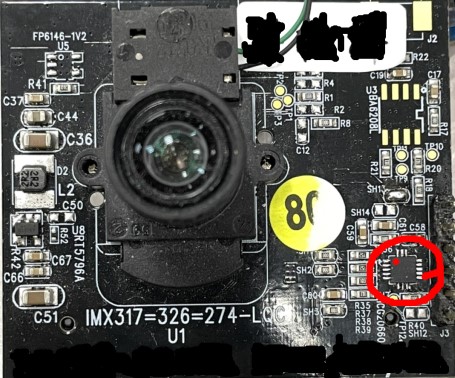
Sensor front right position (The gyroscope is located in the red frame, and the red dot is the PIN 1 position of the gyroscope.)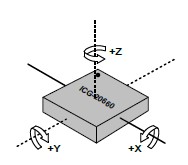
Axis orientation and rotational polarity of gyro sensor ICG-20660PIN 1 position as32RotationMatrix setting 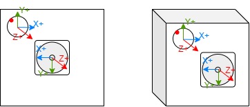
[-1, 0, 0,
0, -1, 0,
0, 0, 1]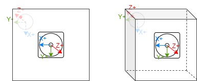
[0, 1, 0,
1, 0, 0,
0, 0, -1]
[0, -1, 0,
1, 0, 0,
0, 0, 1]
[1, 0, 0,
0, -1, 0,
0, 0, -1]
[1, 0, 0,
0, 1, 0,
0, 0, 1]
[0, -1, 0,
-1, 0, 0,
0, 0, -1]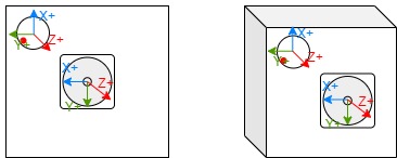
[0, 1, 0,
-1, 0, 0,
0, 0, 1]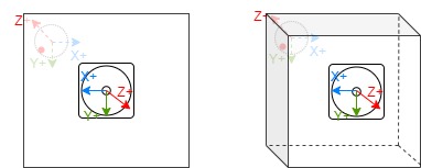
[-1, 0, 0,
0, 1, 0,
0, 0, -1] -
u32UserSliceNum member settings: This input parameter determines how many horizontal slices LDC will divide for DIS (MI_LDC_DIS_GYRO) compensation. If the output height (set by MI_LDC_SetOutputPortAttr) is 1512, then each horizontal slice from top to bottom is 1512/6=252. During setting, pay attention to whether the slice height is close to the value aligned with 32 to avoid unnecessary CPU resources being occupied.
-
u32FocalLengthX and u32FocalLengthY member settings: Focal length setting. The focal length should be converted to pixel unit before input. The conversion formula is: u32FocalLengthX/Y(pixels) = (FocalLength(mm)/CMOS_Unit_CellSize(μm)) * 10^5
FocalLength and CMOS_Unit_CellSize can be found in the lens spec and in the sensor's datasheet.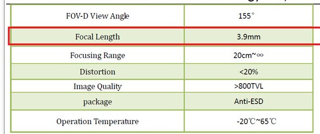
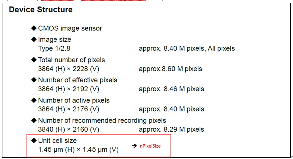
FocalLength (mm) in Lens spec CMOS_Unit_CellSize (μm) in Sensor datasheet When performing zoom operations, u32FocalLengthX/Y (in pixels) needs to be calculated based on HFOV and VFOV at different focal lengths specified in the lens configuration file. The formula is as follows:
· u32FocalLengthX(pixels) = 100*(0.5*InputImageWidth(pixels))/(tan(HFOV(degree)PI/180/2))
· u32FocalLengthY(pixels) = 100(0.5*InputImageHeight(pixels))/(tan(VFOV(degree)*PI/180/2))For example, in some lens configuration files, HFOV is referred to as fov_h, and VFOV is referred to as fov_v
fov_v fov_h InputImageWidth InputImageHeight u32FocalLengthX u32FocalLengthY 68.8 40.51 1920 1080 260152 78866 35.16 20.31 1920 1080 535966 170438 - NOTE: When the current ISP module rotates the image by 90 or 270 degrees, the width and height (W/H) of the input to the LDC module will be swapped compared to the pre-rotated image. In this case, FocalLengthX/Y must also be swapped accordingly
-
pCalIsMatrix member setting: pCalIsMatrix parameters do not support dynamic modification. If modified, the channel must be destroyed and then recreated.
- eMode member setting: eMode parameters do not support dynamic modification. If modified, the channel must be destroyed and then recreated.
- stSrcImgDirection: Set the transformation operation that the front-end has done on the input image, including rotation, mirroring and flipping. The purpose of obtaining this parameter is to correctly perform anti-shake compensation after the front-end transforms the image. Currently, rotation operations only support the ISP module, and mirroring and flipping only support the Sensor module.
- u8BackwardRefFrameCnt : This parameter does not support dynamic modification. If changes are needed, the channel must be destroyed and recreated. This parameter affects the real-time performance and memory usage of the output video frames. It should be set based on the specific anti-shake effect and scenario.
- Impact on real-time performance: The driver internally delays the stabilization processing of the current input frame to after the (u8BackwardRefFrameCnt+1)th frame based on this parameter value;
- Impact on memory usage : Due to the delayed processing of input frames, frame accumulation will occur at the output of upstream modules. To ensure the pipeline operates normally when this parameter is not 0, the MI_SYS_SetChnOutputPortDepth interface must be used to configure the upstream module's output port u32BufQueueDepth to at least u8BackwardRefFrameCnt+1 . Therefore, after enabling this feature, the minimum required buffer between the upstream module and LDC is to cache (u8BackwardRefFrameCnt + 1) frames of image data, i.e., the minimum buffer size required is (u8BackwardRefFrameCnt + 1) × size of each frame.
-
-
Related Data Type and Interface
3.18. MI_LDC_ChnPMFAttr_t
-
Description
Channel attribute for PMF workmode.
-
Definition
typedef struct MI_LDC_ChnPMFAttr_s
{
    MI_S64 as64PMFCoef[LDC_PMFCOEF_NUM];
} MI_LDC_ChnPMFAttr_t;
-
Member
Member name Ranges as64PMFCoef[0] [-67108864, 67106816] as64PMFCoef[1] [-67108864, 67106816] as64PMFCoef[2] [-137438953472, 137434759168] as64PMFCoef[3] [-67108864, 67106816] as64PMFCoef[4] [-67108864, 67106816] as64PMFCoef[5] [-137438953472, 137434759168] as64PMFCoef[6] [-32768, 32767] as64PMFCoef[7] [-32768, 32767] as64PMFCoef[8] 33554432 Parameter Description:
Perspective Mapping Function: (x,y)=F(x0,y0)
Indicates that the input coordinates are calculated from the output coordinates, where x, y are the input image coordinates, and x0, y0 are the output image coordinates.
-
Related Function
3.19. MI_LDC_CalibConfig_t
-
Description
Sensor calibration infomation.
-
Definition
typedef struct MI_LDC_CalibConfig_s { void *pCalibCfgAddr; MI_U32 u32CalibCfgSize; } MI_LDC_CalibConfig_t; -
Member
Member name Description pCalibCfgAddr Buffer Pointer for Calibration information. u32CalibCfgSize Size of Calibration information -
Related Type
3.20. MI_LDC_ProjectionMode_e
-
Description
Projection Mode for stitch workmode
-
Definition
typedef enum { MI_LDC_PROJECTION_RECTILINEAR = 0x00, MI_LDC_PROJECTION_CYLINDRICAL = 0x01, MI_LDC_PROJECTION_SPHERICAL = 0x02, MI_LDC_PROJECTION_BUTT } MI_LDC_ProjectionMode_e; -
Member
Member name Description MI_LDC_PROJECTION_RECTILINEAR Rectilinear projection MI_LDC_PROJECTION_CYLINDRICAL Cylindrical projection MI_LDC_PROJECTION_SPHERICAL Spherical projection MI_LDC_PROJECTION_BUTT Invalid argument -
Related Type
3.21. MI_LDC_ChnStitchAttr_t
-
Description
Channel attribute for Stitch workmode.
-
Definition
typedef struct MI_LDC_ChnStitchAttr_s { MI_LDC_ProjectionMode_e eProjType; MI_S32 s32Distance; MI_LDC_CalibConfig_t stCalCfg; MI_U8 u8PairNum; MI_LDC_StitchDisparity_t astDisparity[LDC_MAX_PAIR_NUM]; } MI_LDC_ChnStitchAttr_t; -
Member
Member name Description eProjType Projection Type s32Distance The distance from the splicing plane to the sensor, measure in millimeters stCalCfg Sensor calibration infomation u8PairNum The number of overlap region astDisparity Disparity map info (Each overlapping region corresponds to a disparity map) -
Related Type
3.22. MI_LDC_ChnNIRAttr_t
-
Description
Channel attribute for NIR workmode.
-
Definition
typedef struct MI_LDC_ChnNIRAttr_s { MI_S32 s32Distance; MI_LDC_CalibConfig_t stCalCfg; } MI_LDC_ChnNIRAttr_t; -
Member
Member name Description s32Distance The distance from the splicing plane to the sensor, measure in millimeters stCalCfg Sensor calibration infomation -
Related Function
3.23. MI_LDC_ChnDPUAttr_t
-
Description
Channel attribute for DPU workmode.
-
Definition
typedef struct MI_LDC_ChnDPUAttr_s { MI_S32 s32Distance; MI_LDC_CalibConfig_t stCalCfg; } MI_LDC_ChnDPUAttr_t; -
Member
Member name Description s32Distance The distance from the splicing plane to the sensor, measure in millimeters stCalCfg Sensor calibration infomation -
Related Function
3.24. MI_LDC_InputPortAttr_t
-
Description
LDC input Port attribute.
-
Definition
typedef struct MI_LDC_InputPortAttr_s { MI_U16 u16Width; MI_U16 u16Height; } MI_LDC_InputPortAttr_t; -
Related Function
3.25. MI_LDC_OutputPortAttr_t
-
Description
LDC Output Port attribute.
-
Definition
typedef struct MI_LDC_OutputPortAttr_s { MI_U16 u16Width; MI_U16 u16Height; MI_SYS_PixelFormat_e ePixelFmt; } MI_LDC_OutputPortAttr_t; -
Related Function MI_LDC_SetOutputPortAttr
3.26. MI_LDC_DirectBuf_t
-
Description
LDC input buffer type.
-
Definition
typedef struct MI_LDC_DirectBuf_s { MI_SYS_PixelFormat_e ePixelFormat; MI_U32 u32Width; MI_U32 u32Height; MI_U32 u32Stride[2]; MI_PHY phyAddr[2]; } MI_LDC_DirectBuf_t; -
Member
Member name Description ePixelFormat Image format u32Width Image width u32Height Image height u32Stride Image occupied bytes per line phyAddr Image storage physical address -
Related Type
3.27. MI_LDC_LutTaskAttr_t
-
Description
LDC image lookup table task type.
-
Definition
typedef struct MI_LDC_LutTaskAttr_s { struct MI_LDC_LutSrcBuf_s { MI_LDC_DirectBuf_t stTableX; MI_LDC_DirectBuf_t stTableY; MI_LDC_DirectBuf_t stTableWeight; } stSrcBuf; MI_LDC_DirectBuf_t stDstBuf; } MI_LDC_LutTaskAttr_t; -
Member
Member name Description stSrcBuf Table data source and weight lookup stDstBuf Store the output data -
Related Function
3.28. MI_LDC_StitchDisparity_t
-
Description
LDC Stitch disparity map info
-
Definition
typedef struct MI_LDC_StitchDisparity_s { void *pMapData; MI_U32 u32MapSize; } MI_LDC_StitchDisparity_t; -
Member
Member name Description pMapData Disparity map data u32MapSize Disparity map data size -
Related Type
3.29. MI_LDC_Point_t
-
Description
The coordinate of mapped border.
-
Definition
typedef struct MI_LDC_Point_s { MI_S16 s16X; MI_S16 s16Y; } MI_LDC_Point_t; -
Member
Member name Description s16X The X-coordinate of mapped border s16Y The Y-coordinate of mapped border -
Related Function
3.30. MI_LDC_DispMapType_e
-
Description
The type of displacement map in the coordinate query function.
-
Definition
typedef enum { E_MI_LDC_DISPMAP_SRC = 0, E_MI_LDC_DISPMAP_DST, E_MI_LDC_DISPMAP_BUTT, } MI_LDC_DispMapType_e; -
Member
Member name Description E_MI_LDC_DISPMAP_SRC The type of displacement map mapping coordinate of input image onto output image E_MI_LDC_DISPMAP_DST The type of displacement map mapping coordinate of output image onto input image E_MI_LDC_DISPMAP_BUTT invalid type -
Related Function and Type
3.31. MI_LDC_DispMapConf_t
-
Description
The config of displacement map in the coordinate query function.
-
Definition
typedef struct MI_LDC_DispMapConf_s { MI_U32 u32RegionIdx; MI_LDC_DispMapType_e eMapType; } MI_LDC_DispMapConf_t; -
Member
Member name Description u32RegionIdx The index of region. For stitching case, the region index increases from left stitching image to right stitching image, starting from 0 eMapType The type of displacement map -
Related Function and Type
3.32. MI_LDC_DispMapSize_t
-
Description
The size of displacement map in the coordinate query function.
-
Definition
typedef struct MI_LDC_DispMapSize_s { MI_U32 u32Width; MI_U32 u32Height; } MI_LDC_DispMapSize_t; -
Member
Member name Description u32Width The width of displacement map u32Height The height of displacement map -
Related Function and Type
3.33. MI_LDC_BaseDrift_t
-
Description
Base drift value of each axis
-
Definition
typedef struct MI_LDC_BaseDrift_s { MI_BOOL bValid; MI_S32 as32BaseDrift[MI_LDC_IMU_AXIS_NUM]; } MI_LDC_BaseDrift_t; -
Member
Member Name Description bValid Indicates whether the data is valid as32BaseDrift Three-axis data, 0 is the x-axis, 1 is the y-axis, 2 is the z-axis -
Note
-
When used in MI_LDC_SetIMUDriftPara, if bValid is set to TRUE, the base drift value will be updated to recalibrate the sensor. If bValid is set to FALSE, the sensor will not be recalibrated.
-
When used in MI_LDC_GetIMUDriftPara, if bValid is TRUE, it means the acquired base drift value is valid. If bValid is FALSE, it means the acquired base drift value is invalid.
-
-
Related Data Type and Interface
3.34. MI_LDC_Drift_t
-
Description
Calibration data
-
Definition
typedef struct MI_LDC_Drift_s { MI_LDC_BaseDrift_t stBaseDrift; } MI_LDC_Drift_t; -
Member
Member Name Description stBaseDrift Base drift value -
Related Data Type and Interface
3.35. MI_LDC_IMUDrift_t
-
Description
Calibration data of the sensor
-
Definition
typedef struct MI_LDC_IMUDrift_s { MI_LDC_Drift_t stGyroDrift; MI_LDC_Drift_t stAccDrift; } MI_LDC_IMUDrift_t; -
Member
Member Name Description stGyroDrift Gyro calibration data stAccDrift Accelerometer calibration data -
Related Data Type and Interface
3.36. MI_LDC_IMUPart_e
-
Description
Calibration part of the sensor
-
Definition
typedef enum { E_MI_LDC_IMU_PART_GYRO = 0x01, E_MI_LDC_IMU_PART_ACC = 0x02, E_MI_LDC_IMU_PART_BUTT = 0x0 } MI_LDC_IMUPart_e; -
Member | Member Name | Description | | -------------------------- | -------------------------- | | E_MI_LDC_IMU_PART_GYRO | Calibrate gyro | | E_MI_LDC_IMU_PART_ACC | Calibrate accelerometer, currently not supported | | E_MI_LDC_IMU_PART_BUTT | Invalid value |
-
Related Data Type and Interface
3.37. MI_LDC_RegionDoorbell_t
-
Description
Correction parameters of doorbell mode.
-
Definition
typedef struct MI_LDC_RegionDoorbell_s { MI_S16 s16Fx; MI_S16 s16Fy; MI_S16 s16A; MI_S16 s16B; MI_S16 s16Scale; } MI_LDC_RegionDoorbell_t; -
Member
Member Name Description s16Fx Horizontal correction strength, value range: [0, 2000] s16Fy Vertical correction strength, value range: [0, 2000] s16A Horizontal scaling, value range: [1000, 4000] s16B Vertical scaling, value range: [1000, 4000] s16Scale Output scaling, value range: [200, 20000] -
Related Data Type and Interface
3.38. MI_LDC_IsMatrixInParam_t
-
Description
The input parameters in the DIS customized callback function. (Provided by the driver)
-
Definition
typedef struct MI_LDC_IsMatrixInPararm_s { MI_LDC_DEV devId; MI_LDC_CHN chnId; MI_U64 u64FramePts; }MI_LDC_IsMatrixInParam_t; -
Member
Member Name Description devId Device ID chnId Channel ID u64FramePts The timestamp corresponding to the image processed -
Related Data Type and Interface
3.39. MI_LDC_IsMatrixOutParam_t
-
Description
The output parameters in the DIS customized callback function. (Provided by the user)
-
Definition
typedef struct MI_LDC_IsMatrixOutParam_s { MI_S32 as32Matrix[LDC_MAXTRIX_NUM]; }MI_LDC_IsMatrixOutParam_t; -
Member
Member Name Description as32Matrix Describes the anti-shake matrix that needs LDC processing -
Note
The elements of this matrix need to be normalized and fixed-pointed. For specific steps, please refer to the IS_UserGuide.
-
Related Data Type and Interface
3.40. MI_LDC_CalIsMatrixCb_t
-
Description
Define DIS customized callback function
-
Definition
typedef MI_S32 (*MI_LDC_CalIsMatrixCb_t)(const MI_LDC_IsMatrixInParam_t * const pstInParam, MI_LDC_IsMatrixOutParam_t * const pstOutParam); -
Related Data Type and Interface
3.41. MI_LDC_ImgDirection_t
-
Description
Describe the transformation operation that the front-end has done on the input image, including rotation, mirroring and flipping.
-
Definition
typedef struct MI_LDC_ImgDirection_s { MI_SYS_Rotate_e eRotate; MI_BOOL bMirror; MI_BOOL bFlip; }MI_LDC_ImgDirection_t; -
Member
Member Name Description eRotate The front-end ISP performs rotate on the image bMirror The front-end Sensor performs mirror on the image bFlip The front-end Sensor performs flip on the image -
Related Data Type and Interface
-
Note
- This parameter does not support dynamic switching. If you need to modify it, you need to destroy the channel and then recreate it.
- eRotate only supports the operation of the ISP module, and bMirror and bFlip only support the operation of the Sensor module.
3.42. MI_LDC_RegionBin_t
-
Description
Binary file information generated by simulation tool CVTool.
-
Definition
typedef struct MI_LDC_RegionBin_s { void *pBinAddr; MI_U32 u32BinSize; } MI_LDC_RegionBin_t; -
Member
Member Name Description pBinAddr Address of binary file u32BinSize Size of binary file -
Related Data Type and Interface
-
Note
- Please confirm that the binary file matches the actual scenario before use to avoid problems caused by mismatches.
-
Example
MI_LDC_DEV          LdcDevid     = 0;
MI_LDC_CHN          LdcChnId     = 0;
MI_LDC_DevAttr_t    stDevAttr    = {};
MI_LDC_ChnAttr_t    stChnAttr    = {};
MI_LDC_ChnLDCAttr_t stChnLDCAttr = {};

stChnAttr.eWorkMode      = MI_LDC_WORKMODE_LDC;
stChnAttr.eInputBindType = E_MI_SYS_BIND_TYPE_FRAME_BASE;

MI_LDC_CreateDevice(LdcDevid, &stDevAttr);
MI_LDC_CreateChannel(LdcDevid, LdcChnId, &stChnAttr);

// For more detailed config, please refer to interface description
// Before calling interface MI_LDC_SetChnLDCAttr, please first call the following interface
// 1. MI_LDC_SetInputPortAttr
// 2. MI_LDC_SetOutputPortAttr

stChnLDCAttr.u32RegionNum                               = 1; // Only supports setting to 1
stChnLDCAttr.stRegionAttr[0].eRegionMode                = MI_LDC_REGION_BIN;
stChnLDCAttr.stRegionAttr[0].stRegionBinInfo.pBinAddr   = 0x00; // Please set it as the actual address
stChnLDCAttr.stRegionAttr[0].stRegionBinInfo.u32BinSize = 0x00; // Please set it as the actual size
MI_LDC_SetChnLDCAttr(LdcDevid, LdcChnId, &stChnLDCAttr);
3.43. MI_LDC_DisAuxiliaryInfo_t
-
Description
Auxiliary info for DIS, u32CurMaxShutter is valid only if bUpdated = TRUE
-
Definition
typedef struct MI_LDC_DisAuxiliaryInfo_s { MI_U32 u32CurMaxShutter; MI_BOOL bUpdated; MI_BOOL bMotion; } MI_LDC_DisAuxiliaryInfo_t; -
Member
Member Name Description u32CurMaxShutter Recommended max shutter bUpdated Whether shutter data is updated bMotion Whether sensor is moving -
Related Data Type and Interface
3.44. MI_LDC_QueryPointsConfig_t
-
Description
Configuration for querying multiple coordinate points.In stitch mode, ignore u32RegionIdx; in LDC mode, ignore stDispMapSize and stDispMapInfo.
-
Definition
typedef struct MI_LDC_QueryPointsConfig_s { MI_U32 u32RegionIdx; MI_LDC_DispMapSize_t stDispMapSize; MI_LDC_DispMapInfo_t stDispMapInfo; } MI_LDC_QueryPointsConfig_t; -
Member
Member Name Description u32RegionIdx Region ID of the query, no need to fill this on MI_LDC_WORKMODE_STITCH mode stDispMapSize The size of displacement map, no need to fill this on MI_LDC_WORKMODE_LDC mode stDispMapInfo The information of displacement map, no need to fill this on MI_LDC_WORKMODE_LDC mode -
Related Data Type and Interface
4. ERROR CODE
LDC API error code is defined in the table below:
| Error Code | Macro Definition | Description |
|---|---|---|
| 0xA0172001 | MI_ERR_LDC_INVALID_DEVID | Invalid device id |
| 0xA0172002 | MI_ERR_LDC_INVALID_CHNID | Invalid channel id |
| 0xA0172003 | MI_ERR_LDC_ILLEGAL_PARAM | Illegal Input argument |
| 0xA0172006 | MI_ERR_LDC_NULL_PTR | Illegal null pointer argument |
| 0xA0172008 | MI_ERR_LDC_NOT_SUPPORT | No support function |
| 0xA017200C | MI_ERR_LDC_NOT_NOMEM | Not enough memory |
| 0xA0172012 | MI_ERR_LDC_BUSY | Channel is busy |
| 0xA0172015 | MI_ERR_LDC_MOD_NOT_INIT | Module is not inited |
| 0xA0172016 | MI_ERR_LDC_MOD_INITED | Module has been inited |
| 0xA0172018 | MI_ERR_LDC_PORT_NOT_DISABLE | Port is not be disable |
| 0xA017201F | MI_ERR_LDC_FAIL | Ldc failed to exec |
| 0xA0172300 | MI_ERR_LDC_DEV_CREATED | Device has been created |
| 0xA0172301 | MI_ERR_LDC_DEV_NOT_CREATE | Device has not been created |
| 0xA0172302 | MI_ERR_LDC_DEV_NOT_DESTROY | Device has not been destroyed |
| 0xA0172303 | MI_ERR_LDC_CHN_CREATED | Channel has been created |
| 0xA0172304 | MI_ERR_LDC_CHN_NOT_CREATE | Channel has not been created |
| 0xA0172305 | MI_ERR_LDC_CHN_NOT_STOP | Channel has not been stopped |
| 0xA0172306 | MI_ERR_LDC_CHN_NOT_DESTROY | Channel has not been destryoed |
| 0xA0172307 | MI_ERR_LDC_PORT_NOT_UNBIND | Port has not been unbinded |
5. PROCFS INTRODUCTION
5.1. cat
-
Debug info
# cat /proc/mi_modules/mi_ldc/mi_ldc<devid> -
Debug info analysis
Record LDC current usage status and relative attributes, which can be dynamically got for debug and test.
-
Parameter Description
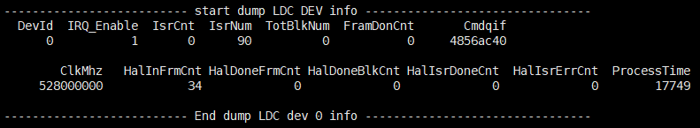
Parameter Description Device Info
DevID Device ID IRQ_Enable IRQ enable state IsrCnt Count of interrupts, cmdq mode has no reference meaning IsrNum Interrupt number TotBlkNum Total number of ldc blocks that need to be processed FramDonCnt Number of processed frames Cmdqif cmdq interface address ClkMhz LDC clock frequency HalInFrmCnt Total number of frames input to Hal HalDoneFrmCnt Total number of frames processed by Hal
HalDoneBlkCnt Total number of blocks processed by Hal HalIsrDoneCnt Number of Hal done interrupts HalIsrErrCnt Number of Hal Err interrupts ProcessTime LDC Hardware processing time 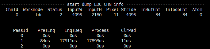
Parameter Description Channel Info
ChnId Channel ID workmode Work mode of current channel status Status of current channel: 0:uninit 1:init 2:start 3:stop 4:destroyed InputWH Input frame resolution Pixel Input frame format Stride Input frame stride[0] InBufCnt The total number of frames input to the pre-level IntodoCnt The label of the frame to be processed (incremental) Atom The number of buf held by the bottom layer PassId 0:DIS 1:LDC 2:STITCH PreTEnq The time applied to output buf. EnqTDeq The total time used from getting pre-level buf to process completion. Process Processing time of front-level buf. ClrPad Time spent cleaning up the padding part of output buf 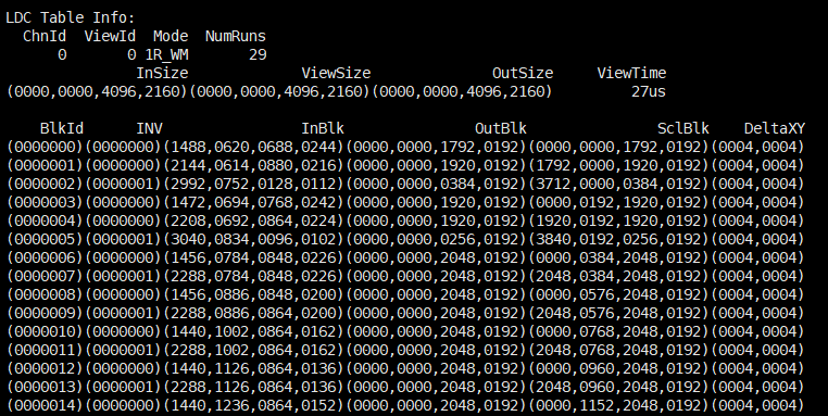
Parameter Description ChnId Channel ID ViewId Ldc corresponding Id mode Scene mode used by ldc NumRuns Total number of blocks that ldc current scene need to run InSize The input area of the current view ViewSize The output area of the current view OutSize The output area of the current scene ViewTime Processing time of the current view BlkId The ID of the current blk INV Whether the current blk has been inverted. Inblk The input area of the current blk OutBlk Algorithm output area of current blk SclBlk The output area of the current blk DeltaXY The coordinates of the current blk corresponding to the delta table 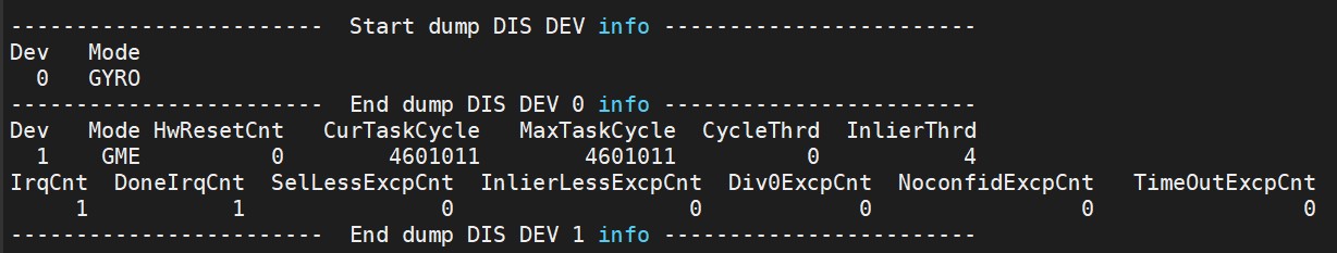
Parameter Description DIS Device Info Dev Device ID Mode Device Mode HwResetCnt Number of DIS HW reset CurTaskCycle Number of cycles taken when DIS HW is processed MaxTaskCycle In the entire pipeline process, the maximum number of cycles processed by DIS HW CycleThrd DIS HW Specifies the threshold of the Cycle for a process. When the threshold is exceeded, TimeoutExcp is triggered InlierThrd The Inlier threshold of a single processing set by DIS HW, less than which will trigger InlierLessExcp IrqCnt number of ISR processed DoneIrqCnt DIS HW number of times that interrupt after completing a frame SelLessExcpCnt DIS HW number of times that small selected point exceptions is triggered InlierLessExcpCnt DIS HW number of times that small inliers point exceptions is triggered Div0ExcpCnt DIS HW number of times that an exception is triggered by division by zero NoconfidExcpCnt DIS HW number of noconfid exceptions triggered TimeOutExcpCnt DIS HW number of timeout exceptions triggered 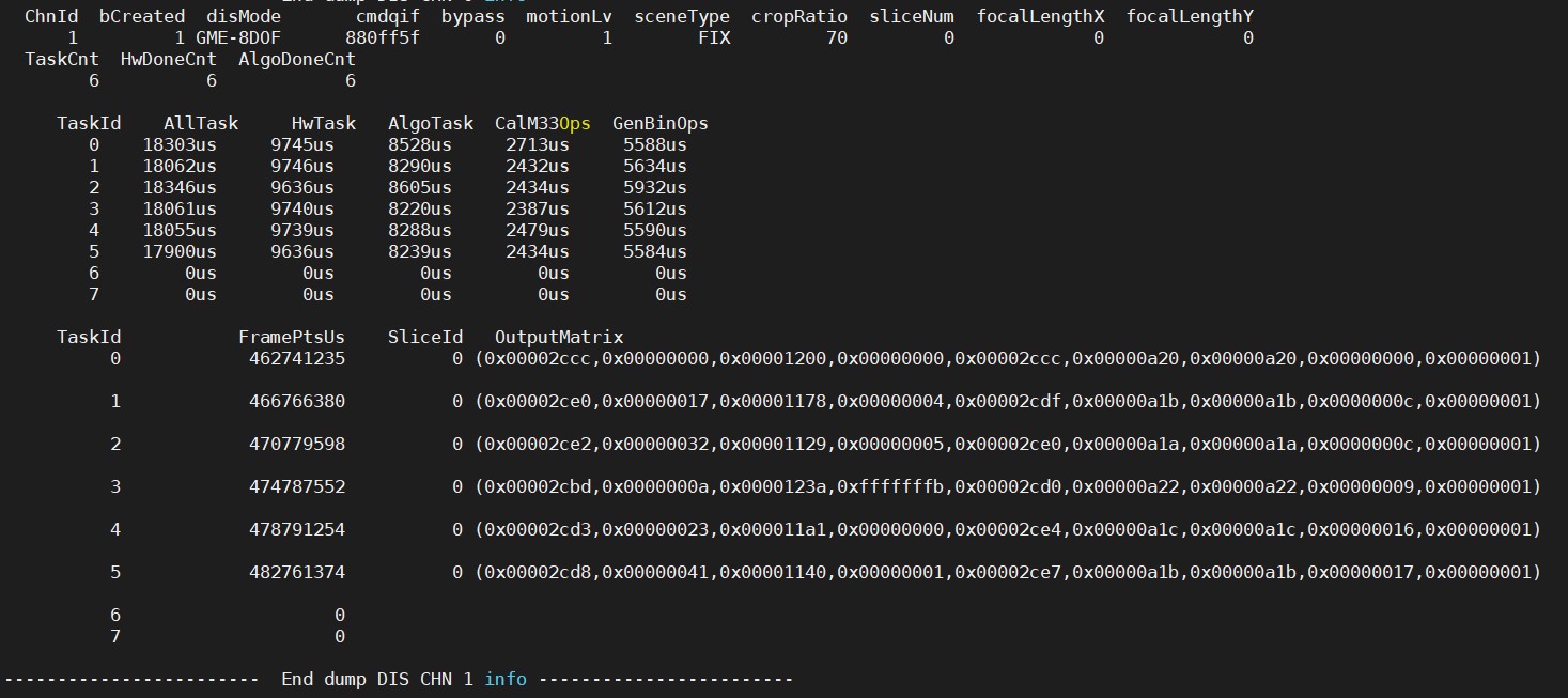
Parameter Description DIS Channel Info ChnId Channel ID bCreated Whether a channel is created disMode DIS mode cmdqif Cmdq interface address motionLv Intensity of lens jitter sceneType The state of the lens cropRatio DIS Image ratio after image cropping sliceNum The number of slices in the vertical direction focalLengthX X-axis focal length focalLengthY Y-axis focal length TaskCnt Number of task done HwDoneCnt Number of HW task done AlgoDoneCnt Number of ALGO task done TaskId The most recent 8 task ID AllTask The total time consumed in this task, in us HwTask The hardware-related time consumed in this task, in us AlgoTask The software-related time consumed in this task, in us CalM33Ops The time consumed by the function to calculate the anti-shake matrix in the software algorithm of this task, in us GenBinOps The time consumed by the function to calculate the LDC transformation mapping area in the software algorithm of this task, in us FramePtsUs The frame timestamp of this task SliceId The slice ID of this task OutputMatrix Anti-shake matrix corresponding to SliceId output in this task 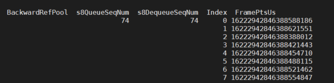
Parameter Description DIS Chnannel BackwardRef Info s8QueueSeqNum Statistical value of accumulated elements in the module internal reference information buffer s8DequeueSeqNum Statistical value of used elements in the module internal reference information buffer Index Index of elements in the module internal reference information buffer FramePtsUs Value of frame timestamp elements in the module internal reference information buffer
5.2. echo
Echo help view available commands:
# echo help > /proc/mi_modules/mi_ldc/mi_ldc<devid>
Take the case where devid is 0 as an example:
| Function | Dump LDC output file |
|---|---|
| Command | echo dumpoutputtask [chnid type cnt path] > /proc/mi_modules/mi_ldc/mi_ldc0 |
| Parameter Description | chnid: channel ID |
| type: dump data type. 0:dis; 1:ldc; 2:stitch | |
| cnt: dump count | |
| path: dump path | |
| Example | echo dumpoutputtask 0 1 2 /mnt/ > /proc/mi_modules/mi_ldc/mi_ldc0 |
| Function | Dump LDC input file |
|---|---|
| Command | echo dumpinputtask [chnid type cnt path] > /proc/mi_modules/mi_ldc/mi_ldc0 |
| Parameter Description | chnid: channel id |
| type: dump data type. 0:dis; 1:ldc; 2:stitch | |
| cnt: dump count | |
| path: dump path | |
| Example | echo dumpinputtask 0 1 2 /mnt/ > /proc/mi_modules/mi_ldc/mi_ldc0 |
| Function | Dump LDC map file |
|---|---|
| Command | echo dumpalgobin [chnid view/all path] > /proc/mi_modules/mi_ldc/mi_ldc0 |
| Parameter Description | chnid: channel ID |
| view/all: dump content view: the specific viewid all: all the views of the current scene. |
|
| path: dump path | |
| Example | echo dumpalgobin 0 all /mnt/ > /proc/mi_modules/mi_ldc/mi_ldc0 |
| Function | Show the debug info about DIS HW |
|---|---|
| Command | echo dis_sel_dbgcfg [chn_id cfg_id] > /proc/mi_modules/mi_ldc/mi_ldc0 |
| Parameter Description | chn_id: channel id |
| cfg_id: debug level of the configuration, range[1, 5] | |
| Example | echo dis_sel_dbgcfg 0 1 > /proc/mi_modules/mi_ldc/mi_ldc0 |
| Function | Set the threshold of the number of DIS HW inliers |
|---|---|
| Command | echo dis_cfg_inlier_thrd [chn_id thrd] > /proc/mi_modules/mi_ldc/mi_ldc0 |
| Parameter Description | chn_id: channel id |
| thrd: inliers threshold,range[1, 7] | |
| Example | echo dis_cfg_inlier_thrd 0 1 > /proc/mi_modules/mi_ldc/mi_ldc0 |
| Function | Set the cycle threshold for DIS HW processing |
|---|---|
| Command | echo dis_cfg_cycle_thrd [chn_id thrd] > /proc/mi_modules/mi_ldc/mi_ldc0 |
| Parameter Description | chn_id: channel id |
| thrd: cycle threshold,range[0, 2147483647] | |
| Example | echo dis_cfg_cycle_thrd 0 1 > /proc/mi_modules/mi_ldc/mi_ldc0 |
| Function | Bypass DIS anti-shake function (keep the same angle of view) |
|---|---|
| Command | echo dis_bypass [chn_id switch] > /proc/mi_modules/mi_ldc/mi_ldc0 |
| Parameter Description | chn_id: channel id |
| switch: whether to enable (0-off, 1-on) | |
| Example | echo dis_bypass 0 0 > /proc/mi_modules/mi_ldc/mi_ldc0 |
| Function | Set DIS algorithm log level |
|---|---|
| Command | echo dis_loglv [chn_id loglv] > /proc/mi_modules/mi_ldc/mi_ldc0 |
| Parameter Description | chn_id:channel id |
| loglv:log level | |
| Example | echo dis_loglv 0 3 > /proc/mi_modules/mi_ldc/mi_ldc0 |
| Function | Set the log level for the correction algorithm in DIS mode |
|---|---|
| Command | echo calib_loglv [chn_id loglv] > /proc/mi_modules/mi_ldc/mi_ldc0 |
| Parameter Description | chn_id:channel id |
| loglv:log level | |
| Example | echo calib_loglv 0 3 > /proc/mi_modules/mi_ldc/mi_ldc0 |