Burning Instructions
1. HW Related Environment Preparation
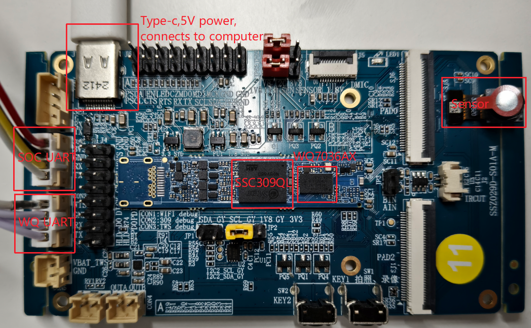
1.1 Power Supply & DebugUart
-
Unified power supply: DC 5V, which also supports the firmware update of the main control SSC309QL via this USB port.
-
Arm debugging serial port: CON10 ARM DBG, TTL level, default baud rate: 115200, used to connect to the debugging serial port of the main control SSC309QL.
-
TWS debugging serial port: WQ7036AX (Bluetooth chip), CON 11 TWS DBG, used to connect to the debugging or firmware burning of TWS Soc, as shown in the figure below.
1.2 Board Boot Mode Selection
The Comake PI D2 board defaults to the EMMC boot mode.
2 Writing the main control SSC309QL
2.1 USB Factory Tool Burning
The USB Factory Tool is a burning tool for the Sigmastar empty chip, and it will be packaged in the same directory as the image when compiling the empty chip burning image. After normal compilation generates the image, you can find the USB Factory Tool at image/output/images/Usb_Ufu_Upgrade/exe/.
2.1.1 Non-empty chip burning
Requirement Scenario:
A complete PCB is available, with a USB interface, and ensure that the system can enter uboot mode.
Implementation Principle:
There is already uboot in the emmc. Moreover, this version of uboot supports device ufu mode for upgrading via PC by executing commands to interact with uboot and PC software to complete the download and upgrade.
Under this mode, the existing uboot in the emmc must have ufu upgrade capability, and the uboot supports ufu commands with the default burning image enabled. For specific methods to configure uboot, please refer to 3.1 uboot Support Upgrade Configuration.
If the emmc is not an empty chip, the device will not automatically boot to Uboot when powered on; you need to hold down the enter key on a computer keyboard, then power on the device, and after the device enters uboot, enter the command ufu command in the Iford uart serial terminal, then follow the steps below.
Operational Steps:
-
Compile the SDK normally to generate the image upgrade file.
-
After the entire SDK package compilation is successful, execute
make image-usb-factoryto create the upgrade image, and you can find the upgrade file named USB_UPGRADE_UFU.bin underimage/output/images/Usb_Ufu_Upgrade/.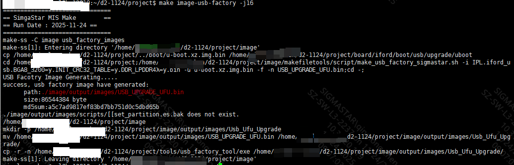
-
There are three ways to open the uboot upgrade function; here we recommend the second method. The other three methods can be found in 3.1 uboot Support Upgrade Configuration.
If the emmc is not an empty chip, the device will not automatically boot to Uboot when powered on. You need to hold down the enter key on a computer keyboard, then power on the device, and enter the command
ufu commandin the Iford uart serial terminal to enter device upgrade mode.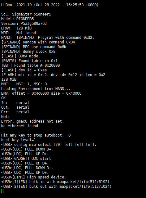
-
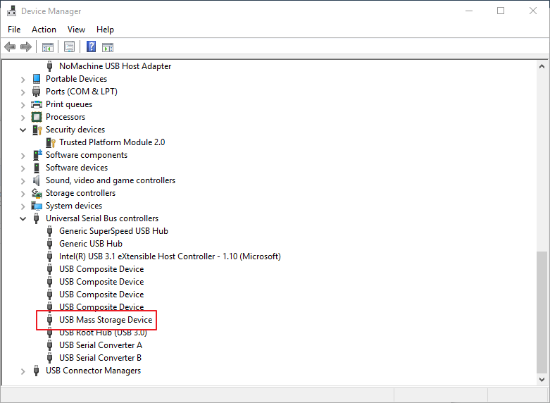
Power on and connect USB. You can observe that a storage device is connected to the PC.
-
The PC connects to the board that needs to be upgraded via usbhub (the board flash must be an empty chip). In the
project/image/output/images/Usb_Ufu_Upgrade/exe/directory, selectUSB_Factory_Tool_64_1.0.0.19.exe, open USB Factory Tool.exe, which will display as follows: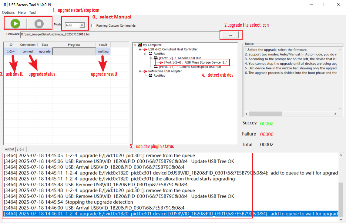
The functionalities of various icons in the figure are as follows:
0→ Two burning modes
-
auto mode, generally used in production lines, can automatically detect device connection and upgrade.
-
Manual mode, generally used for development, requires selecting a specific device for upgrading. You need to manually select the upgrade device (USB mass storage device) and then click the upgrade button.
1→ Start and stop buttons for the upgrade. It should be noted that the stop button can only be pressed after all connected devices have successfully upgraded.
2→ Upgrade package selection button: used to select the upgrade package file for the USB empty chip.
3→ USB device upgrade status and results display area. It should be noted that there are currently two statuses for the empty chip upgrade: preparing and upgrading. You must wait until the upgrade status is successful before unplugging the USB device and connecting another USB device for upgrading.
4→ Displays currently recognized USB devices.
5→ USB device insertion status log.
-
-
After selecting the USB upgrade package file, wait for all connected devices to be recognized, and click the start button to proceed with the upgrade. The interface after the upgrade is complete is as follows:
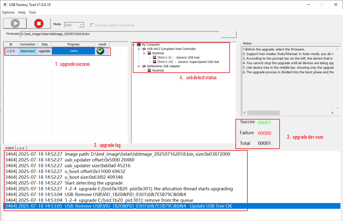
The functionalities of various icons in the figure are as follows:
1→ Displays the upgrade results of each device.
2→ Displays the upgrade logs of each device.
3→ Displays the total number of connected devices and their upgrade status.
4→ Displays the detected USB devices. It should be noted that after a successful upgrade, the detected USB devices will be removed.
Based on the upgrade status displayed for each device by 1→ , proceed with the following actions:
-
Upgrade Successful: Unplug the corresponding device and plug in another empty chip to continue upgrading.
-
Upgrade Failed: You can try unplugging and plugging the device back in to see if it works.
-
2.1.2. Empty Chip Burning
If the emmc is an empty chip, you need to burn the image of TWU1WQ7036 (Bluetooth chip) first, refer to 2.2 Bluetooth WQ7036AX Burning, and control the WTS pin to connect to 3.3V to enable the Iford USB connection; otherwise, you cannot burn normally. Refer to Figure 1.1 showing the TWS pins. The subsequent steps can refer to steps 4, 5, and 6 of 2.1.1 Non-empty Chip Burning.
2.2 OTA Upgrade
For details, please refer to OTA Upgrade Usage Reference.
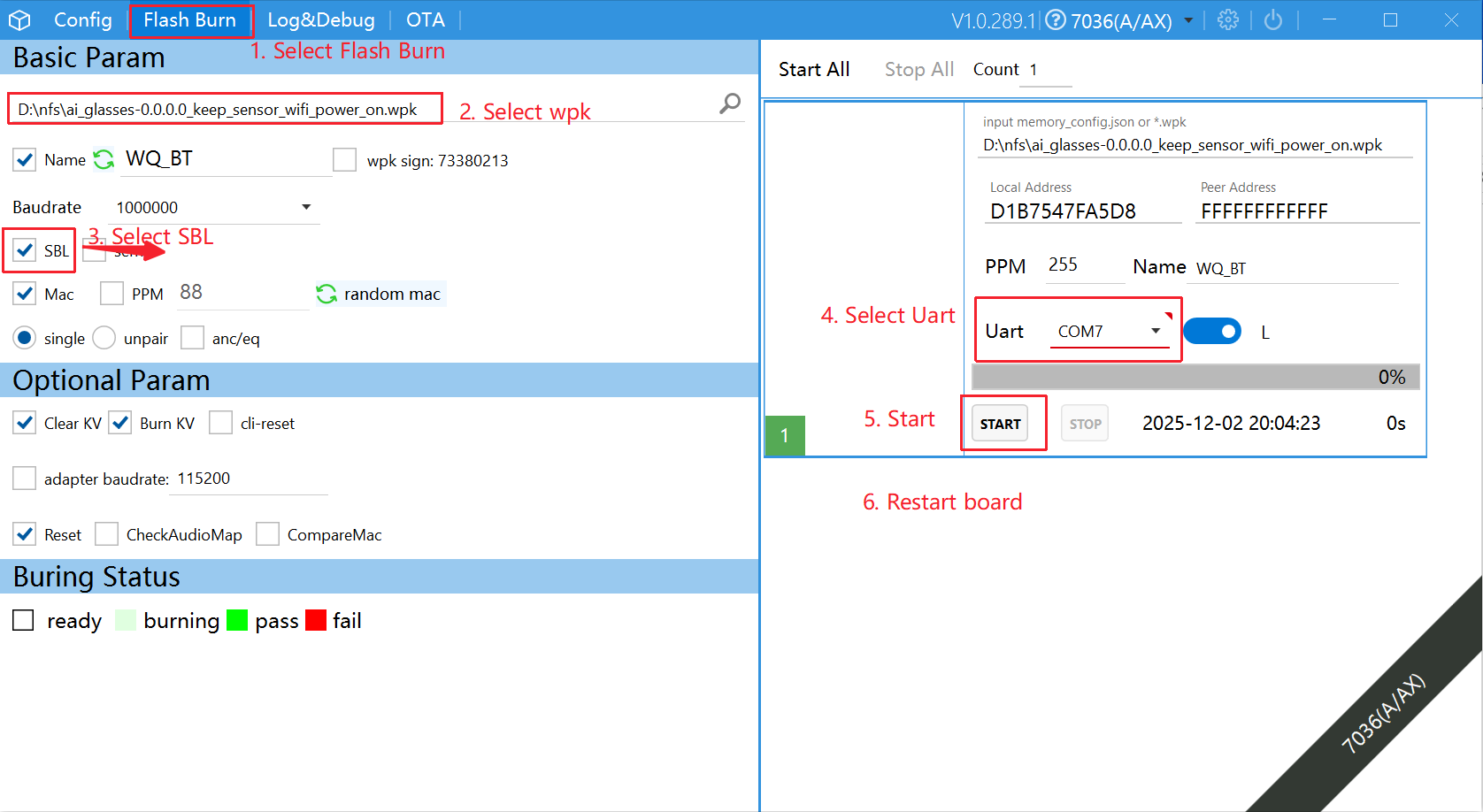
3 Bluetooth WQ7036AX Burning
For hardware connections, you can refer to Figure 1.1 showing the TWU1WQ interface. Be sure to select the SBL checkbox during the first burn. Make sure to pull the WTS pin high to 3.3V. The specific burning steps are as follows:
- Select Flash Burn.
- Select the firmware to be burned.
- Select SBL.
- Select the corresponding serial port.
- Click Start.
-
Note: After clicking the Start button, you need to power the board again!
4. FAQ
4.1 uboot Support Upgrade Configuration
4.1.1 uboot Support Upgrade Configuration
    location:
    Command line interface
        --> SigmaStar common commands
            --> [*] ufu
4.1.2 Three Ways to Enable ufu
Method One:
Enter the boot directory of the SDK and input make menuconfig, then select autoboot ufu by env (ota_upgrade_status) according to the following selections:
    location:
    Command line interface
        --> SigmaStar common commands
            --> [*] ufu
            --> [*] autoboot ufu by env (ota_upgrade_status)
Then enter the uboot mode on the board. The device will not automatically boot to Uboot when powered on; you need to hold down the enter key on a computer keyboard, power on the device, and enter the following commands:
setenv ota_upgrade_status 1
saveenv
Method Two:
In uboot mode, directly enter ufu command to enter device upgrade mode.
Method Three: (Enter UFU Mode via GPIO Key Detection)
Enter the boot directory of the SDK and input make menuconfig, then select autoboot ufu by gpio according to the following selection:
    location:
    Command line interface
        --> SigmaStar common commands
            --> [*] ufu
            --> [*] autoboot ufu by gpio
Power on the device. After booting, if uboot detects a key trigger, it will automatically enter device ufu upgrade mode.
If you need to specify the corresponding GPIO, you need to configure it as follows and recompile and burn uboot.
To configure the specified key state: modify the boot/common/autoboot.c file to set FORCE_UPGRADE_GPIO (specified IO), FORCE_UPGRADE_ACTIVE_HIGH (specified state) as shown in the following figure:
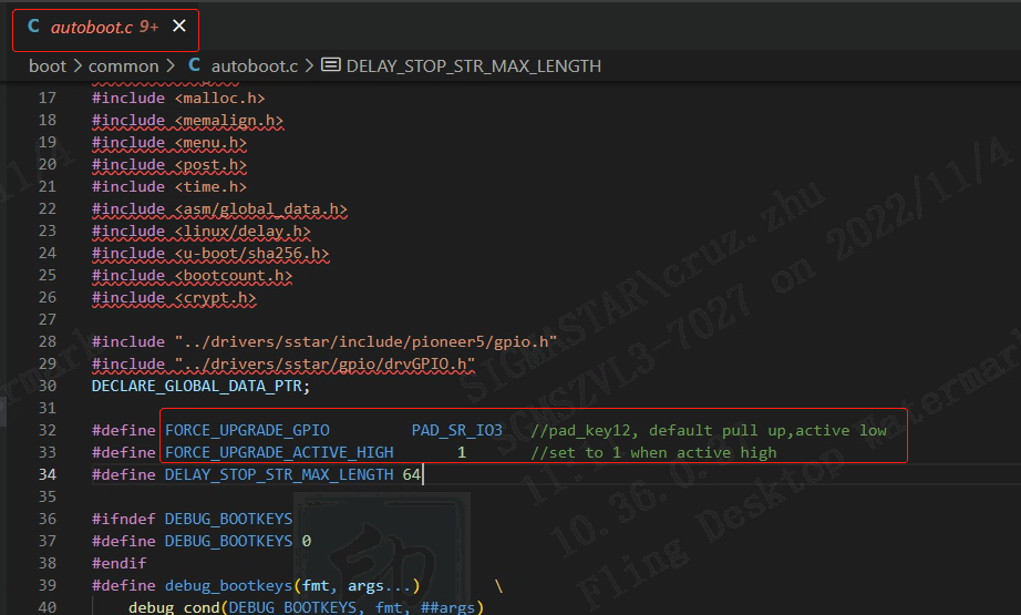
Implementation Principle: During uboot startup, check the specified state of the specified IO to decide whether to enter ufu mode (device upgrade mode). The relevant code is implemented in autoboot.c; feel free to study it if you are interested.