GPIO User Guide
REVISION HISTORY
| Revision No. | Description |
Date |
|---|---|---|
| 1.0 | 01/22/2024 | |
| 1.1 | 11/08/2025 |
1. Overview
General Purpose Input/Output (GPIO) is abbreviated as GPIO. GPIO uses the standard Linux framework, enabling unified interface operations.

The GPIO framework is shown in the diagram above. The middle layer is gpiolib, which manages the GPIO in the system. gpiolib summarizes the general operations of GPIO. Based on the characteristics of GPIO, gpiolib provides a unified and universal software interface for operating GPIO to the upper layers (other drivers). Lower layers, gpiolib provides a framework for different chip operations. For different chips, only mdrv_gpio_io.c needs to be implemented, and then the registration function provided by gpiolib is used to connect it to gpiolib.
2. Keyword Explanation
2.1. GPIO Index
The GPIO pad name on the schematic can be found in Table 1-1 to determine the corresponding GPIO Index. The GPIO Index is used as an input parameter for software functions that operate on the GPIO.
For example: If the desired GPIO is PAD_GPIO4, the corresponding GPIO Index found in Table 1-1 is 12.
Table 1-1: GPIO Index and PAD Correspondence Table
| Pad Name | GPIO Index | Pad Name | GPIO Index | Pad Name | GPIO Index |
|---|---|---|---|---|---|
| PAD_I2C1_SDA | 0 | PAD_SR_RST0 | 1 | PAD_SR_MCLK0 | 2 |
| PAD_I2C1_SCL | 3 | PAD_SR_RST1 | 4 | PAD_SR_MCLK1 | 5 |
| PAD_I2C2_SCL | 6 | PAD_I2C2_SDA | 7 | PAD_GPIO0 | 8 |
| PAD_GPIO1 | 9 | PAD_GPIO2 | 10 | PAD_GPIO3 | 11 |
| PAD_GPIO4 | 12 | PAD_GPIO5 | 13 | PAD_GPIO6 | 14 |
| PAD_GPIO7 | 15 | PAD_GPIO8 | 16 | PAD_GPIO9 | 17 |
| PAD_GPIO10 | 18 | PAD_GPIO11 | 19 | PAD_SD0_CDZ | 20 |
| PAD_SD0_D1 | 21 | PAD_SD0_D0 | 22 | PAD_SD0_CLK | 23 |
| PAD_SD0_CMD | 24 | PAD_SD0_D3 | 25 | PAD_SD0_D2 | 26 |
| PAD_FUART_RTS | 27 | PAD_FUART_CTS | 28 | PAD_FUART_RX | 29 |
| PAD_FUART_TX | 30 | PAD_MSPI_CZ | 31 | PAD_MSPI_DO | 32 |
| PAD_MSPI_DI | 33 | PAD_MSPI_CK | 34 | PAD_SPI0_DO | 35 |
| PAD_SPI0_DI | 36 | PAD_SPI0_HLD | 37 | PAD_SPI0_WPZ | 38 |
| PAD_SPI0_CZ | 39 | PAD_SPI0_CK | 40 | PAD_I2C0_SDA | 41 |
| PAD_I2C0_SCL | 42 | PAD_PM_GPIO12 | 43 | PAD_PM_GPIO11 | 44 |
| PAD_PM_UART_TX | 45 | PAD_PM_UART_RX | 46 | PAD_PM_PSPI0_INT | 47 |
| PAD_PM_PSPI0_DI | 48 | PAD_PM_PSPI0_DO | 49 | PAD_PM_PSPI0_CK | 50 |
| PAD_PM_PSPI0_CZ | 51 | PAD_PM_GPIO10 | 52 | PAD_PM_GPIO9 | 53 |
| PAD_PM_GPIO8 | 54 | PAD_PM_GPIO7 | 55 | PAD_PM_PWM3 | 56 |
| PAD_PM_PWM2 | 57 | PAD_PM_PWM1 | 58 | PAD_PM_PWM0 | 59 |
| PAD_PM_GPIO6 | 60 | PAD_PM_GPIO5 | 61 | PAD_PM_GPIO4 | 62 |
| PAD_PM_UART2_TX | 63 | PAD_PM_UART2_RX | 64 | PAD_PM_I2C_CLK | 65 |
| PAD_PM_I2C_SDA | 66 | PAD_PM_SDIO_INT | 67 | PAD_PM_GPIO3 | 68 |
| PAD_PM_GPIO2 | 69 | PAD_PM_GPIO1 | 70 | PAD_PM_GPIO0 | 71 |
| PAD_PM_SDIO_D1 | 72 | PAD_PM_SDIO_D0 | 73 | PAD_PM_SDIO_CLK | 74 |
| PAD_PM_SDIO_CMD | 75 | PAD_PM_SDIO_D3 | 76 | PAD_PM_SDIO_D2 | 77 |
| PAD_PM_FUART_RTS | 78 | PAD_PM_FUART_CTS | 79 | PAD_PM_FUART_RX | 80 |
| PAD_PM_FUART_TX | 81 | PAD_PM_HSRAM_GPIO0 | 82 | PAD_PM_HSRAM_GPIO1 | 83 |
| PAD_PM_HSRAM_GPIO2 | 84 | PAD_PM_HSRAM_GPIO3 | 85 | PAD_PM_HSRAM_GPIO4 | 86 |
| PAD_PM_HSRAM_GPIO5 | 87 | PAD_PM_HSRAM_GPIO6 | 88 | PAD_PM_HSRAM_GPIO7 | 89 |
| PAD_PM_HSRAM_GPIO8 | 90 | PAD_PM_HSRAM_GPIO9 | 91 | PAD_PM_HSRAM_GPIO10 | 92 |
| PAD_PM_HSRAM_GPIO11 | 93 | PAD_PM_HSRAM_GPIO12 | 94 | PAD_PM_SAR_GPIO0 | 95 |
| PAD_PM_SAR_GPIO1 | 96 | PAD_PM_SAR_GPIO2 | 97 | PAD_PM_SAR_GPIO3 | 98 |
| PAD_PM_SAR_GPIO4 | 99 | PAD_OUTN_RX0_CH5 | 100 | PAD_OUTP_RX0_CH5 | 101 |
| PAD_OUTN_RX0_CH4 | 102 | PAD_OUTP_RX0_CH4 | 103 | PAD_OUTN_RX0_CH3 | 104 |
| PAD_OUTP_RX0_CH3 | 105 | PAD_OUTN_RX0_CH2 | 106 | PAD_OUTP_RX0_CH2 | 107 |
| PAD_OUTN_RX0_CH1 | 108 | PAD_OUTP_RX0_CH1 | 109 | PAD_OUTN_RX0_CH0 | 110 |
| PAD_OUTP_RX0_CH0 | 111 |
3. Function Description
-
Supports configuring the pull-up/pull-down state of GPIO pins
-
Supports configuring the drive capability of GPIO pins
4. Hardware Connection
Simply connect the corresponding GPIO pin to the hardware.
5. U-Boot Usage Introduction
5.1. U-Boot Config Description
[*] SigmaStar drivers --->

    [*] SigmaStar GPIO

    [*] SigmaStar padmux
5.2. Related Code Paths
drivers/sstar/gpio/drv_gpio.c
drivers/sstar/gpio/drv_gpio.h
drivers/sstar/gpio/chip_name/hal_gpio.c
drivers/sstar/gpio/chip_name/hal_gpio.h
drivers/sstar/gpio/chip_name/hal_pinmux.c
drivers/sstar/gpio/chip_name/hal_pinmux.h
drivers/sstar/include/chip_name/gpio.h
drivers/sstar/include/chip_name/padmux.h
5.3. DTS Parameter Configuration Instructions
gpio: gpio {
    compatible = "sstar,gpio";
    status = "okay";
};
| Attributes | Description | Remarks |
|---|---|---|
| compatible | Used for driver matching and registration | Modification prohibited |
| status | Driver on/off | Configure as needed, ok/disabled |
5.4. Uboot cmd Parameter Description
<input|set|clear|toggle> <pin> → input/set/clear/toggle the specified pin
gpio status [-a] [<bank> | <pin>] → show [all / claimed] GPIOs
| cmd | Parameters | Description |
|---|---|---|
| input | pin | Sets the pin with pin number pin to GPIO input mode |
| set | pin | Sets the pin with pin number pin to GPIO output high mode |
| clear | pin | Sets the pin with pin number pin to GPIO output low mode |
| toggle | pin | Toggle the voltage level of the pin with pin number pin |
5.5. Uboot cmd usage examples
gpio input <gpio#> → gpio input 69 // gpio69 set as input
gpio set <gpio#> → gpio set 10 // gpio10 set as output high
gpio clear <gpio#> → gpio clear 49 // gpio49 set as output low
gpio toggle <gpio#> → gpio toggle 49 // gpio49 level toggle
gpio status <gpio#> → gpio status 20 // gpio20 status
6. Kernel Usage Introduction
6.1. Kernel config Configuration Instructions
Device Drivers  --->

    [*] GPIO Support  --->
        [*]   /sys/class/gpio/... (sysfs interface)

    [*] SStar SoC platform drivers  --->
        [*]   Sstar GPIO driver
        [*]   PADMUX driver
6.2. Related Code Paths
drivers/sstar/gpio/drv/drv_gpio.c
drivers/sstar/gpio/drv/drv_gpio.h
drivers/sstar/gpio/hal/chip_name/src/hal_gpio.c
drivers/sstar/gpio/hal/chip_name/inc/hal_gpio.h
drivers/sstar/gpio/hal/chip_name/src/hal_gpio_common.c
drivers/sstar/gpio/hal/chip_name/src/hal_pinmux.c
drivers/sstar/gpio/hal/chip_name/inc/hal_pinmux.h
drivers/sstar/gpio/hal//chip_name/pub/gpio.h
drivers/sstar/gpio/hal/chip_name/pub/padmux.h
drivers/sstar/gpio/os/gpio_os.h
drivers/sstar/gpio/ut/gpio_irq_test.c
6.3. DTS Parameter Configuration Instructions
gpio: gpio {
    compatible = "sstar,gpio";
    #gpio-cells = <2>;
    status = "okay";
};
| Attributes | Description | Remarks |
|---|---|---|
| compatible | Used for driver matching and registration | Modification is prohibited |
| #gpio-cells | Declares the number of GPIO cells in the device node | Configuring it to 2 means the first cell is the GPIO number, and the second cell represents the active GPIO level |
| status | Driver on/off | Configure as needed, ok/disabled |
6.4. Module Usage Introduction
6.4.1. Export/Unexport File Interface
Userspace can manipulate GPIOs via the sysfs interface.
The source code for /sys/class/gpio is located in driver/gpio/gpiolib-sysfs.c.
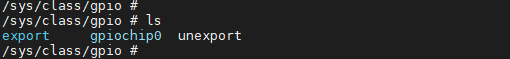
The /sys/class/gpio directory contains three files: export/unexport, gpioN, and gpio_chipN.
| Filename | Read/Write Permissions | Value | Description |
|---|---|---|---|
| export | wo | GPIO Index | Requests control of a specific GPIO in user space |
| unexport | wo | GPIO Index | Removes control of a specific GPIO from user space |
| gpioN | ro | Contains information such as the direction and value of the specific GPIO | |
| gpio_chipN | ro | Refers to the GPIO controller |
The GPIO index can be found in drivers/sstar/include/CHIPNAME/gpio.h
-
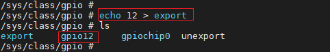
The file /sys/class/gpio/export is write-only. User programs request control of a specific GPIO port from the kernel (sysfs) by writing its number, provided no kernel code has already requested that port. For example, the command to request GPIO port number 12 is:
# echo 12 > exportThe above operation will create a node gpio12 for GPIO with GPIO Index 12. At this time, a directory gpio12 will be generated under the /sys/class/gpio directory, as shown in the figure below:
-
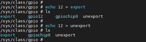
/sys/class/gpio/unexport The file attributes are also set to write-only, the opposite of
export. Users remove user-space (sysfs) interfaces by writing the GPIO number. For example, the command to remove the gpio12 folder is:# echo 12 > unexportThe above operation will remove the gpio12 node, as shown in the following figure:
6.4.2. /sys/class/gpio/gpioN
/sys/class/gpio/gpioN refers to a specific GPIO port, and contains the following property file:
| file name | Read and write permissions | value | describe |
| direction | rw | in | Input mode, value is not writable |
| out | Output mode, value is writable | ||
| high | Output status: default is high level; value can be written. | ||
| low | Output status: default low level; value can be written. | ||
| value | rw | 1 | high level state |
| 0 | low level state | ||
| edge | rw | none | disable GPIO interrupt |
| rising | Enable GPIO interrupts and set them to rise-edge triggered. | ||
| falling | Enable GPIO interrupts and set them to fall-edge triggered. | ||
| both | Enable GPIO interrupts and set them to double-edge triggered. |
direction Indicates the direction of the GPIO port; the read result is either in or out. The read command is:
# cat direction
value This indicates the voltage level of the GPIO pin, where 0 represents low and 1 represents high. The read command is:
# cat value
Write operations can be performed on a direction using the following command:
# echo in > direction
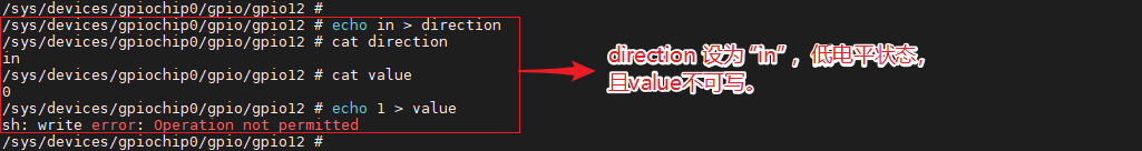
# echo out > direction
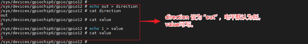
If the direction is configured as output (out), the level is low by default, and the value is writable. The operation command is:
# echo 1 > value

# echo 0 > value
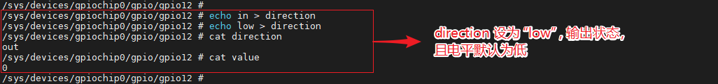
When writing "direction" to "low" or "high", it can not only be set as output but also specify a particular output level. The operation command is:
# echo high > direction
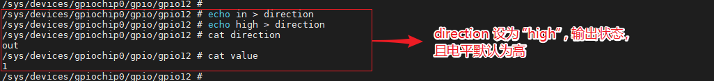
# echo low > direction
Of course, this attribute will not exist if the kernel does not support it or the kernel code does not want to. For example, if the kernel calls gpio_export(N,0), it means that the kernel does not want to modify the GPIO port direction attribute.
edge indicates whether to enable GPIO interrupts and sets the trigger mode, supporting rising edge triggering, falling edge triggering, and double edge triggering:
# cat edge
You can perform write operations on the edge using the following command:
# echo none > edge
# echo rising > edge
# echo falling > edge
# echo both > edge
If you need to enable an interrupt for a certain pin, you need to first set that pin to the input state and set the trigger mode. Then you can call the poll(2) function to listen for the interrupt. After the interrupt is triggered, the poll(2) function will return.
6.4.3. /sys/class/sstar/msys
The Linux GPIO framework does not currently support GPIO pull-up/pull-down and drive capability adjustment configurations. In addition to the standard Linux GPIO framework, we have added an extra file interface for manipulating GPIO pull-up/pull-down and adjusting drive capabilities. To support this feature, you first need to enable the CONFIG_MSYS_GPIO configuration, which is located in menuconfig.
Device Drivers  --->

    [*] SStar SoC platform drivers  --->
        [*]   support GPIO pull and driving modify
        [*]   support padmux modify and verify
The source code for /sys/class/sstar/msys is located in driver/sstar/msys/ms_msys.c.
Before setting up pull-up/pull-down, the GPIO must first be set to input mode. Output pull-up/pull-down states cannot be measured.

After setting the pin to input mode, navigate to the sys/class/mstar/msys folder:
-
gpio_pull You can write up and down.
file name Read and write permissions value describe gpio_pull rw up Pull-up mode down drop-down mode To check the current pull status of GPIO, see pull up / pull down / pull off:
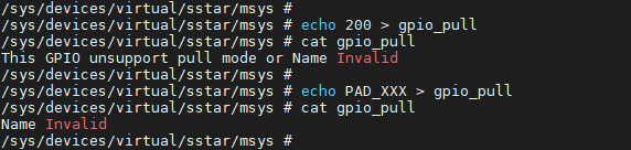
1. # echo 50 >  gpio_pull
2. # cat gpio_pull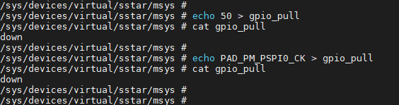
An error will occur if an invalid GPIO Index and GPIO Name are entered:
The commands to set the drop-up and drop-down are:
1. # echo 50 up > gpio_pull
2. # echo 50 down > gpio_pull
After setting it, check the status of gpio_pull, as shown in the figure below. 50 represents the GPIO Index, and PAD_OUTN_RX0_CH3 represents the GPIO Name.
1. # cat gpio_pull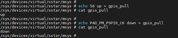
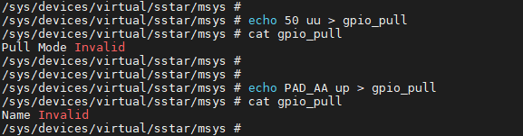
An error will occur if an invalid GPIO Index and GPIO Name are entered:
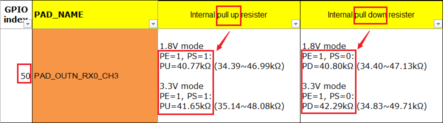
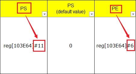
To check if a specific bit has been written correctly, you can look up the corresponding PAD in the GPIO_Mapping_Table (see GPIO INDEX: 50 in the image below). When pulling up, the PE bit is 1 and the PS bit is 0; when pulling down, the PE bit is 1 and the PS bit is 0. The specific operation command is as follows:
1. # riu_r 0x103e 0x34Check BIT6 and BIT11 of the riu_r return value.
-
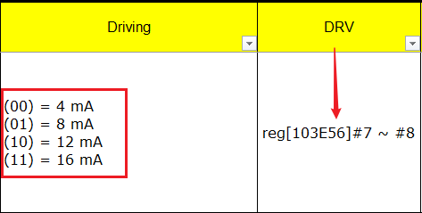
gpio_drive The level that can be written to the driver
Filename Read/Write Permissions Value Description gpio_drive rw 0~8 Sets the GPIO drive level The driver capability level of GPIO in the current platform can be found in the GPIO_Mapping_Table.
To view the command bit for the initial driver capability level of a GPIO: (Alternatively, you can directly use the GPIO43 name PAD_OUTP_RX0_CH0)
1. # echo 43 > gpio_drive
2. # cat gpio_drive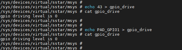
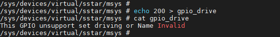
An error will occur if an invalid GPIO Index and GPIO Name are entered:
Before configuring the drive capability, set the GPIO to a high-level output state for easy measurement. The configuration command is:
1. # echo 43 1 > gpio_drive43 represents the GPIO Index, and 1 represents the drive capability level, corresponding to 4mA.
After setting the drive capability, check the status of gpio_driver. As shown in the figure below, setting the drive capability of the pin with GPIO Index 43 to 4mA was successful.
1. # cat gpio_drive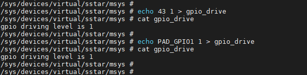
To check if a specific bit has been written correctly, you can look up the corresponding pad in the GPIO_Mapping_Table (see GPIO INDEX: 50 in the image below). When the driver level is set to 1, [103E56]#7 ~ #8 are 01. The specific operation command is:
1. # riu_r 0x103e 0x2BCheck the BIT7 and BIT8 of the riu_r return value.
-
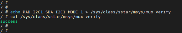
mux_verify Used to identify reuse conflicts
Filename Read/Write Permissions Value Description mux_verify rw 0~8 Confirm if there are any conflicts in the reuse functionality Taking the operation of PAD_I2C1_SDA's PINMUX_FOR_I2C1_MODE_1 as an example:
1. # echo PAD_I2C1_SDA I2C1_MODE_1 > /sys/class/sstar/msys/mux_verify
2. # cat mux_verify
The following display indicates that the settings are correct and there are currently no reuse conflicts.
The following display indicates that a reuse issue exists.

Please check register value of [bank: 0x103E, offset: 0x00, mask: 0x0008]
Correct value is not 0x0008, but current value is 0x0008
The problematic register address is: [bank: 0x103E, offset: 0x00, mask: 0x0008]. The correct value is not 0x0008 because the mask is 0x0008 (BIT3 == 0x0008), so BIT3 should be 0. However, BIT3 is currently equal to 1, and BIT3 needs to be cleared.
Please check register value of [bank: 0x103C, offset: 0x53, mask: 0x0003]
Correct value is 0x0001, but current value is 0x0000
The problematic register address is: [bank: 0x103C, offset: 0x53, mask: 0x0003]. The correct value is 0x0001 because the mask is 0x0003 (BIT1|BIT0==0x0003). Therefore, BIT0 should be 1 and BIT1 should be 0.
-
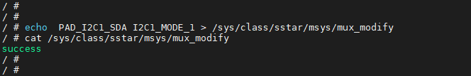
mux_modify Used to configure multiplexing functionality
Filename Read/Write Permissions Value Description mux_modify rw 0~8 Configure multiplexing functionality Taking PINMUX_FOR_I2C1_MODE_1 for PAD_I2C1_SDA as an example:
6.4.4. Multiplexing Function Usage Instructions
When using GPIO multiplexing, you first need to obtain the Name of the pin to be operated and the Tmux Mode to be multiplexed, and configure them in xxx-padmux.dtsi:
1. <PAD_VSYNC_OUT PINMUX_FOR_VGA_VSYNC_MODE_1 MDRV_PUSE_VGA_VSYNC>

2. <PAD_HSYNC_OUT PINMUX_FOR_VGA_HSYNC_MODE_1 MDRV_PUSE_VGA_HSYNC>
As shown above, the first and second columns represent the Pad Name and Tmux Mode, respectively. MDRV_PUSE_XXX can be understood as the Name of the current configuration group.
Important points to note during configuration:
-
A Pad can only be configured with one Mode; multiple Modes cannot be configured on a single Pad simultaneously.
-
A Puse can only correspond to one set of configurations; otherwise, conflicts will occur. - The configured Pad and Mode must match.
-
Reuse operations are not allowed directly in the driver; all reused configurations must be centralized in xxx_padmux.dtsi. (Except for configurations that require dynamic adjustment of reused settings, this is for ease of management and to reduce configuration conflicts.)
6.5. Sample Code
User-space code enables GPIO interrupt reference demo.
1.    #include <stdio.h>
2.    #include <stdlib.h>
3.    #include <unistd.h>
4.    #include <fcntl.h>
5.    #include <sys/poll.h>
6.
7.    int main(int argc, char *argv[])
8.    {
9.        char buff[1024];
10.        int gpio_id;
12.        struct pollfd fds[1];
13.        int gpio_fd = open("/sys/class/gpio/gpio135/value", O_RDONLY);
14.        if (gpio_fd == -1)
15.            {printf("gpio open\n");}
16.        else
17.            {printf("/sys/class/gpio/gpio135/value\n");}
18.        fds[0].fd = gpio_fd;
19.        fds[0].events = POLLPRI;
20.        int ret = read(gpio_fd, buff, 10);
21.        if (ret == -1)
22.            printf("read fail\n");
23.        else
24.            printf("read\n");
25.        while (1)
26.        {
27.            printf("revents is %d\n", fds[0].revents);
28.            ret = poll(fds, 1, -1);
29.            if (ret == -1)
30.                printf("poll\n");
31.
32.            if (fds[0].revents & POLLPRI)
33.            {
34.                ret = lseek(gpio_fd, 0, SEEK_SET);
35.                if (ret == -1)
36.                    printf("lseek\n");
37.                ret = read(gpio_fd, buff, 10);
38.                if (ret == -1)
39.                    printf("read\n");
40.                printf("get interrupt\n");
41.            }
42.        }
43.    }
7. API参考
This functional module provides the following interfaces:
| API Name | Function |
|---|---|
| gpio_request | Request a GPIO port |
| gpio_free | Release a GPIO port |
| gpio_direction_input | Mark a GPIO as an input |
| gpio_direction_output | Mark a GPIO as an output |
| gpio_get_value | Get the voltage level of an input pin |
| gpio_set_value | Set the voltage level of an output pin |
| sstar_gpio_pad_set | Sets the pin to gpio_mode |
| sstar_gpio_pad_clr | Clears the pin's gpio_mode |
| sstar_gpio_pad_val_set | Sets the pin's tmux mode |
| sstar_gpio_pad_val_get | Gets the PadMode currently configured for a specific pad. |
| sstar_gpio_vol_val_set | Gets the voltage level of an input pin. This interface is only supported by Muffin. |
| sstar_gpio_pad_in_out | Determines the input/output status of a pin. |
| sstar_gpio_pull_up | Enables pull-up functionality for a specified GPIO pin. |
| sstar_gpio_pull_down | Enables pull-down functionality for a specified GPIO pin. |
| sstar_gpio_pull_off | Disables the specified GPIO pull-up/pull-down functionality and switches it to an unattended state. |
| sstar_gpio_pull_status | Get the pull-up/pull-down status of the specified GPIO. |
| sstar_gpio_drv_set | Set the driver capability of the specified GPIO. |
| sstar_gpio_drv_get | Get the driver capability level of the specified GPIO. |
| sstar_gpio_to_irq | Get the interrupt number of the GPIO that is known to you. |
| sstar_gpio_name_to_num | Get the GPIO index by GPIO name. |
| sstar_gpio_padmode_to_padindex | Queries all GPIO pins that can use a specific padmode. |
| drv_padmux_getpad | Retrieves the pad configured in the DTSI with puse. |
| drv_padmux_getmode | Retrieves the tmux mode configured in the DTSI with puse. |
| drv_padmux_getpuse | Gets the macro definition of puse. |
7.1. gpio_request
-
Purpose
Create a GPIO port.
-
Syntax
int gpio_request(unsigned gpio, const char *label) -
Parameters
Parameter Name Description gpio GPIO Index label Specific Name -
Return Value
Return Value Description 0 Success other Failure
7.2. gpio_free
-
Purpose
Free up a GPIO port.
-
Syntax
void gpio_free(unsigned gpio) -
Parameters
Parameter Name Description gpio GPIO Index -
Return Value
Return Value Description void None
7.3. gpio_direction_input
-
Purpose
Mark GPIO as input.
-
Syntax
int gpio_direction_input(unsigned gpio); -
Parameters
Parameter Name Description gpio GPIO Index -
Return Value
Return Value Description 0 Success other Failure
7.4. gpio_direction_output
-
Purpose
Mark GPIO as output.
-
Syntax
int gpio_direction_output(unsigned gpio, int value); -
Parameters
Parameter Name Description gpio GPIO Index value Output value -
Return Value
Return Value Description 0 Success other Failure
7.5. gpio_get_value
-
Purpose
To obtain the voltage level of an input pin.
-
Syntax
int gpio_get_value(unsigned gpio); -
Parameters
Parameter Name Description gpio GPIO Index -
Return Value
Return Value Description int Voltage Level
7.6. gpio_set_value
-
Purpose
Sets the voltage level of an output pin.
-
Syntax
void gpio_set_value(unsigned gpio, int value); -
Parameters
Parameter Name Description gpio GPIO Index value Output Value -
Return Value
Return Value Description 0 Success other Failure
7.7. sstar_gpio_pad_set
-
Purpose
Sets the pin to GPIO MODE.
-
Syntax
void sstar_gpio_pad_set(u8 gpio_index); -
Parameters
Parameter Name Description gpio_index GPIO Index -
Return Value
Return Value Description void None
7.8. sstar_gpio_pad_clr
-
Purpose
Clear the GPIO MODE of the pin.
-
Syntax
void sstar_gpio_pad_clr(u8 gpio_index); -
Parameters
Parameter Name Description gpio_index GPIO Index -
Return Value
Return Value Description void None
7.9. sstar_gpio_pad_val_set
-
Purpose
Sets the TMUX mode of a pin.
-
Syntax
u8 sstar_gpio_pad_val_set(u8 gpio_index, u32 pad_mode); -
Parameters
Parameter Name Description gpio_index GPIO Index pad_mode TMUX MODE -
Return Value
Return Value Description 1 Output parameter error 0 Success
7.10. sstar_gpio_vol_val_set
-
Purpose
This API is used to retrieve the current PadMode of a specific Pad, provided that the PadMode was configured via the Padmux interface. Direct register manipulation will not make this API effective.
-
Syntax
void sstar_gpio_vol_val_set(u8 group, u32 mode); -
Parameters
Parameter Name Description gpio_index Group Index pad_mode The retrieved TMUX MODE -
Return Value
Return Value Description 1 Output parameter error 0 Success
7.11. sstar_gpio_vol_val_set
-
Purpose
To obtain the voltage level of the input pin. Note that this interface is only supported by Muffin.
-
Syntax
void sstar_gpio_vol_val_set(u8 group, u32 mode); -
Parameters
Parameter Name Description group Group num (11 Groups in total) mode Mode = 0: Pin voltage is 3.3V; Mode = 1: Pin voltage is 1.8V -
Return Value
Return Value Description void None
7.12. sstar_gpio_pad_in_out
-
Purpose
Determine whether a pin is in the input or output state.
-
Syntax
u8 sstar_gpio_pad_in_out(u8 gpio_index, u8* pad_in_out); -
Parameters
Parameter Name Description gpio_index GPIO Index pad_in_out 0 indicates the pin is in the output state, 1 indicates the pin is in the input state -
Return Value
Return Value Description 1 Input parameter error 0 Success
7.13. sstar_gpio_pull_up
-
Purpose
Enables pull-up functionality for the specified GPIO pin.
-
Syntax
u8 sstar_gpio_pull_up(u8 gpio_index); -
Parameters
Parameter Name Description gpio_index GPIO Index -
Return Value
Return Value Description 0 Successfully set other This pin does not support pull-up settings or the input parameter is incorrect
7.14. sstar_gpio_pull_down
-
Purpose
Enables pull-down functionality for the specified GPIO pin.
-
Syntax
u8 sstar_gpio_pull_down(u8 gpio_index); -
Parameters
Parameter Name Description gpio_index GPIO Index -
Return Value
Return Value Description 0 Successfully set other This pin does not support pull-down settings or the input parameter is incorrect
7.15. sstar_gpio_pull_off
-
Purpose
Disables the pull-up/pull-down function of the specified GPIO and switches it to a floating state.
-
Syntax
u8 sstar_gpio_pull_off(u8 gpio_index); -
Parameters
Parameter Name Description gpio_index GPIO Index -
Return Value
Return Value Description 0 Successfully set other This pin does not support pull-up settings or the input parameter is incorrect
7.16. sstar_gpio_pull_status
-
Purpose
To obtain the pull-up/pull-down status of a specified GPIO pin.
-
Syntax
u8 sstar_gpio_pull_status(u8 gpio_index, u8* pull_status); -
Parameters
Parameter Name Description gpio_index GPIO Index pull_status The obtained pull-up/pull-down status -
Return Value
Return Value Description 0 Successful acquisition 1 This pin does not support pull-up settings or the input parameters are incorrect
7.17. sstar_gpio_drv_set
-
Purpose
Sets the drive capability of a specified GPIO pin.
-
Syntax
u8 sstar_gpio_drv_set(u8 gpio_index, u8 level); -
Parameters
Parameter Name Description gpio_index GPIO Index level Drive capability level -
Return Value
Return Value Description 0 Successfully set other This pin does not support drive capability setting or the input parameter is incorrect
7.18. sstar_gpio_drv_get
-
Purpose
Retrieves the drive capability level of a specified GPIO pin.
-
Syntax
u8 sstar_gpio_drv_get(u8 gpio_index, u8* level); -
Parameters
Parameter Name Description gpio_index GPIO Index level The drive capability level of the obtained GPIO pin -
Return Value
Return Value Description 0 Successful acquisition 1 The pin does not support drive capability setting or the input parameter is incorrect
7.19. sstar_gpio_to_irq
-
Purpose
Retrieves the interrupt number of a specified GPIO.
-
Syntax
int sstar_gpio_to_irq(u8 gpio_index); -
Parameters
Parameter Name Description gpio_index GPIO Index -
Return Value
Return Value Description virq Virq is the returned interrupt number Negative or 0 Failure
7.20. sstar_gpio_name_to_num
-
Purpose
To obtain the GPIO Index by GPIO Name.
-
Syntax
u8 sstar_gpio_name_to_num(u8* p_name, u8* gpio_index); -
Parameters
Parameter Name Description p_name GPIO Name gpio_index GPIO Index obtained -
Return Value
Return Value Description 1 Incorrect input parameter 0 Success
7.21. sstar_gpio_padmode_to_padindex
-
Purpose
To query all GPIO pins that can use a specific PadMode.
-
Syntax
u32* sstar_gpio_padmode_to_padindex(u32 mode); -
Parameters
Parameter Name Description mode The PadMode to query -
Return Value
Return Value Description Array start address Array storing GPIO Indexes
7.22. drv_padmux_getpad
-
Purpose
Use Puse as the search criterion to retrieve the Pads configured in xxx-padmux.dtsi.
-
Syntax
int drv_padmux_getpad (int Puse); -
Parameters
Parameter Name Description Puse Macro definition of Puse -
Return Value
Return Value Description PadId Successfully retrieved the macro definition of Pad in padmux.dtsi PAD_UNKNOWN The input Puse is incorrect or there is no corresponding PadId in padmux.dtsi
7.23. drv_padmux_getmode
-
Purpose
To retrieve the Tmux Mode configured in xxx-padmux.dtsi by iterating through the database using Puse as the search criterion.
-
Syntax
int drv_padmux_getmode (int Puse); -
Parameters
Parameter Name Description Puse Macro definition of Puse -
Return Value
Return Value Description PadId Successfully retrieved the macro definition of Mode from padmux.dtsi PAD_UNKNOWN The input Puse is incorrect or there is no corresponding PadId in padmux.dtsi
7.24. drv_padmux_getpuse
-
Purpose
Because the macro definition of PUSE follows a set of rules:
-
The offset between different IPs is 0x10000
-
The offset between different Channels within the same IP is 0x100
-
The offset between different Puse instances within the same Channel of the same IP is 0x1
Therefore, the macro definition of Puse can be obtained based on these three parameters.
-
-
Syntax
int drv_padmux_getpuse (int IP_Index, int Channel_Index, int Pad_Index); -
Parameters
Parameter Name Description IP_Index The IP address of Puse, which can be found in mdrv_puse.h Channel_Index The channel where Puse is located, which can be found in mdrv_puse.h Pad_Index The index of Puse in the channel, which can be found in mdrv_puse.h -
Return Value
Return Value Description Puse Successfully retrieved the PadId from padmux.dtsi
8. FAQ
When encountering errors while operating GPIO, please refer to the following points for troubleshooting:
| Common Problems | Troubleshooting Directions |
|---|---|
| export cannot pull high or low | Actual voltmeter measurement, direct write to register |
| padmode error | Use the iocheck tool to check if the padmode setting is correct |
8.1. Direct Register Writing
Pull the register of the corresponding GPIO pin high or low, and use a voltmeter to measure any changes to determine whether the error is due to an incorrect CAT value or a incorrect SET value.
8.2. Using the iocheck Tool
In the directory kernel/drivers/sstar/gpio/ut/io_check, simply run make to generate the prog_io_check tool. Package it to the customer partition and it's ready to boot and use.
Supported options are as follows:
| Option | Function |
|---|---|
| -s | Set padmux mode |
| -g | Get padmux mode |
| -i | Specify pin number |
| -m | Specify mode |
| -v | Check padmux mode conflict |
Example: Query a GPIO pin with its index:
Query current multiplexing status: ./prog_io_check -i index
Set to the corresponding mode: ./prog_io_check -i index -m mode_index -s