System Partition
REVISION HISTORY
| Revision No. | Description |
Date |
|---|---|---|
| 1.0 | 03/20/2024 | |
| 2.0 | 08/29/2024 |
1. Pure Linux
System startup is divided into several stages, each with different functions. Before the operating system runs, there are generally the following stages: Rom code, IPL, IPL_CUST, CM4, TEE, and UBOOT. The binary files of each stage are stored in the flash. During the startup process, partitions are needed to manage the location of each stage in the flash. Except that Rom code directly reads the IPL block from cis and then jumps to IPL execution, other code jumps need to read the partition information of the next stage of code from the partition table for jump.
The following is an example of the specific role of each code in the startup phase:
-
ROM CODE
The initial startup code in the CPU is fixed in the hardware and cannot be modified. This startup code is called Rom code. It will eventually read the machine code at a fixed address in the flash and jump to execute. This address is the first address where the binary of the IPL code is stored.
When using Spi-nor flash, Rom code will read the IPL code segment from Flash address 0 and execute it; when using spi-nand, the situation will be a bit complicated because it is necessary to consider the bad blocks in the manufacturing process of Spi-nand.
In Spi-nand, rom code will read CIS information from address 0 of flash. CIS stores some basic attribute information of Spi-nand flash, such as a Block size, Page size, etc. The two key data provided in CIS are named BL0 PBA/BL1 PBA, which is the Block index value. Rom code can find the location of IPL in Flash through this value. As shown in the figure below, Rom code will determine whether the Block specified by BL0 PBA is a bad block or ECC ERR. If three consecutive blocks are bad blocks or ECC ERR, IPL will be guided from BL1 PBA. Similarly, three blocks will be judged continuously starting from BL1 PBA. If they are all bad blocks or ECC ERR, it cannot be started.

Figure 1: Rom Code Loading IPL ProcessCIS
Spinand is saved at the address of flash 0, and Nor is saved after the IPL partition. It contains three parts. The first part is GCIS, which contains a general flash information. Its purpose is to make the rom code adapt to the parameters of most flashes so that the boot can enter the IPL smoothly. Another part of flash info saves some basic information of flash, such as block page count, block count, etc., hereinafter referred to as SNI, which will change according to the type of flash. The last part is partition info, which saves partition information, hereinafter referred to as PNI. When the Linux system is started, the partition information is replaced by the mtdparts of uboot to follow the native partition process of Linux. In mtdparts, except for the BOOT partition used to make One bin, which is different from PNI, other partition information must be equal to that in PNI. The difference is that from PNI, you can see a more detailed distribution in the BOOT partition of mtdpars, such as the specific location of IPL/IPL_CUST/UBOOT.
IPL/IPL_CUST
After the CPU is powered on, the first thing that runs is the rom code. At this stage, only the CPU is working and the DDR has not been initialized. The SOC provides sram inside to load a section of code for execution. This section of code is called IPL. Since the sram is very small, only a few dozen kb, the code size of the IPL must be controlled within the size range of the sram. The IPL code mainly initializes the DDR. Only after the initialization is completed can the larger uboot code be loaded.
IPL_CUST will be executed after IPL, and will initialize the executable binary file of the customized board hardware according to the actual situation of the current board, such as customized GPIO management, IIC configuration, and will also access the env partition. IPL_CUST will finally decide which code to run next based on the current compilation configuration. It can choose to run uboot, CM4, TEE, or Linux kernel. In the fast startup solution, IPL_CUST can ignore uboot and jump directly to the Linux kernel.
UBOOT
Native open source bootloader code.
CM4
In addition to the dual-core ARM Cortex-A32 core, the Sigmastar Iford system chip is equipped with an additional ARM Cortex-M4 low-power core, namely CM4. CM4 runs the freertos system alone, and the system image occupies a separate partition PM_RTOS in the flash. The PM_RTOS image will only be used in scenarios that include CM4.
TEE
The Cortex-A32 CPU is divided into two worlds: secure world and non-secure world. The secure world runs the tee (Open Portable Trusted Execution Environment) system, also known as OP-TEE. TEE can be regarded as a trusted OS at the same level as the Linux kernel. The system image has no separate partition and is packaged together in the BOOT0/1 partition. The non-secure world may run Linux alone or Linux+freertos at the same time. Linux and freertos have their own partitions KERNEL and RTOS. TEE images are only used in scenarios that include trustzone.
Before the Linux kernel starts, the CPU will execute several pieces of code respectively:

Figure 2: Boot flowThe process can be initiated at the IPL_CUST stage through a Flag, which can be either an environment variable or the state of a GPIO pin. Currently, the default flow during startup is the blue line flow. If the Flag is true, the red line flow will be taken, skipping U-Boot. The main functions of U-Boot are to upgrade the image and provide native MTD support.
1.1 Partition Content
1.1.1 ONE BIN Partition
ONE BIN function is based on ALKAID's packaging script, which uses the dd command to merge the BOOT PART partitions into a bin. From the perspective of uboot, you can enter the command mtdpart in uboot to see the current partition plan. The difference from pni is that the BOOT PART part is no longer divided into internal partitions, but is composed of one BOOT partition. One bin integrates several different boot codes in the startup phase into one binary, which can simplify the complexity of the bootloader phase partition, making it easier to maintain. At the same time, by splicing different code binaries together, you don't have to consider the alignment requirements of the partition size, thereby saving the binary size of the flash boot code. The specific layout of onebin is shown in the figure below:
NOR FLASH
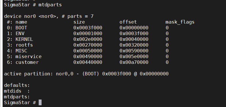
Figure 3: Composition of NOR PartitionSPINAND FLASH

Figure 4: Composition of NAND PartitionAfter ONE BIN is packaged, a boot.bin will be generated under output/images/. boot.bin is composed of the images of ipl/ipl_cust/uboot, and nor flash will add an additional cis partition.
The composition of One bin is used to distinguish Spi-nand or Spi-nor. The following table lists the composition of One bin in different boot configurations:
Boot mode Nand flash boot.bin composition Nor flash boot.bin composition Prue linux + uboot IPL + IPL_CUST + UBOOT IPL + CIS + IPL_CUST + UBOOT Prue linux + uboot + CM4 IPL + IPL_CUST + UBOOT IPL + CIS + IPL_CUST + UBOOT Prue linux + uboot + TRUST ZONE IPL + IPL_CUST + TEE + UBOOT IPL + CIS + IPL_CUST + TEE + UBOOT Prue linux + uboot + CM4 + TRUST ZONE IPL + IPL_CUST + TEE + UBOOT IPL + CIS + IPL_CUST + TEE + UBOOT The blank flash programming of One Bin is different from that of non-One Bin systems. The bins and addresses to be programmed are as follows:
-
SPINAND
Burned bin Flash location Description cis.bin 0x0/0x20000 Burn both locations once boot.bin 0x140000 -
SPINOR
Burned bin Flash location Description boot.bin 0x0
1.1.1.1. SPINAND BOOT Partition
On nand flash, BOOT0/BOOT1 belong to the A/B partition. The ROM code is started from the BOOT0 partition by default. If the BOOT0 partition has an ECC ERROR or encounters a bad block, it will jump to the BOOT1 partition and start from the BOOT1 partition by default after the next startup. This ensures that during the upgrade process, a backup mechanism is established for the BOOT part to avoid being unable to enter the UBOOT cmd line after the BOOT upgrade fails.
As mentioned above, the ONE BIN part is spliced by the dd command, and its specific composition is as follows:
< img style = "border-radius: 0.3125em; box-shadow: 0 2px 4px 0 rgba(34,36,38,.12),0 2px 10px 0 rgba(34,36,38,.08);" src="./mymedia/partitionfile/partitionfile-6.svg" width = "100%" alt=""/>
Figure 5: Composition of NAND Flash ONE BIN PartitionThe orange part in the above figure represents the size of the partition in MTD PART, boot.bin represents the actual size of the one bin, and the purple part represents the layout of this part in pni.
The IPL/IPL_CUST image usually does not exceed the size of one block, so they and their backups each occupy 3 blocks, which is a fixed size.
UBOOT data occupies 2 blocks. Since uboot is often customized, the size of the uboot image may change. Therefore, configuring 2 blocks cannot guarantee all situations. If you want to modify it, please modify
uboot$(DATASIZE) = 0x40000in the config file.1.1.1.2. Bad Block Processing in SPINAND BOOT Partition
A gap of four blocks is reserved in UBOOT. This part is mandatorily reserved in the config file. The four blocks are provided to make full use of the BK BLK of IPL and IPL_CUST (each of them has two backups, which add up to 4). The mandatory reserved code is as follows:
uboot$(PATSIZE) = $(call sum, $(uboot$(DATASIZE)) $(call multiplyhex, $(FLASH_BLK_SIZE), 4))The purpose of the reservation is to handle the bad block situation. From the above figure, we can see that the BOOT partition of MTD PART is 4 blocks larger than the boot.bin to be burned. When using tftp or burner to burn the code, if a bad block is encountered, the data will automatically be written to the next block, and the data after the current position will be shifted as a whole.
Assuming a bad block occurs at the location of IPL_CUST DATA, the following will be displayed after burning:

Figure 6: One Bin Structure after Bad Block TreatmentAll data after IPL_CUST is shifted by one block, so the data in uboot will also be shifted by one block, and GAP will occupy one block. In the case of no bad blocks, the entire boot partition allows a maximum of 4 blocks of bad blocks. These 4 bad blocks are not in any random position, and they must satisfy that at least one block in the IPL/IPL_CUST partition is good. If there are more than 4 blocks or the above conditions are not met, it will jump to the BOOT1 partition to ensure smooth startup.
1.1.1.3. BL0 PBA/BL1 PBA Flag of SPINAND
You can use the tool SpiNandInfoEditor.exe to open flash.sni or flash_list.sni and view the following fields:

Figure 7: The flash location of boot.binThese two fields are used to find the IPL partition for the rom code. The sni files found in ALKAID/project/board are filled with 0 by default, and the unit is block count. This means that the rom code looks for IPL0 and IPL from the default address. The default address is 0x140000 for IPL0 and 0x1A0000 for IPL1, which obviously does not match the current partition configuration. So during the production of cis.bin, a shell script will be used to fill in the correct values for BL0 PBA and BL1 PBA in flash.sni and flash_list.sni, which correspond to the block offset corresponding to the start address of the BOOT0/BOOT1 partition on the flash.
1.1.1.4. SPINOR BOOT Partition
SPINOR currently does not have A/B partitions by default, and is different from SPINAND in the BOOT part. The BOOT partition of SPINOR includes CIS, and the BOOT partition starts from address 0. The structure of the BOOT partition is as shown below.

Figure 8: Composition of Nor Flash ONE BIN PartitionSince SPINOR does not need to deal with bad blocks, IPL and IPL_CUST do not have backup blocks. In the boot partition, you need to pay attention to the alignment of the partition's start address, end address and partition size. The reason for aligning with 4k is to save space. In boot, the start address and partition size of the IPL/IPL_CUST/UBOOT/CIS partition must be aligned with one nor flash page, which is 4k in size. The ENV partition is not in the BOOT partition, but it requires that the end address of the ENV partition be aligned with one NOR flash block, which is generally 64k in size. So, according to the layout set forth in the figure below, there will be a GAP between UBOOT and ENV to ensure this alignment requirement is satisfied. The function of this GAP is different from that of spinand. In addition to ensuring the alignment requirements, it also serves the function of a buffering mechanism to deal with changes in the data part of UBOOT/IPL/IPL_CUS that cause changes in the internal partition of PNI. The purpose of this function is to ensure that even if these partitions change in PNI, the BOOT partition and env partition of MTD will remain unchanged. This leaves a larger amount of change for OTA to upgrade to BOOT (considering that the ota upgrade partition cannot be changed).
The partition sizes of IPL/IPL_CUST/CIS/UBOOT in the NOR flash partition are automatically 4k aligned in the script. You need only to adjust the size of the MTD BOOT partition to increase or decrease the GAP.
The size of BOOT is limited. Its size plus the partition size of ENV must be aligned with block size. The variable that sets its size is:
boot$(PATSIZE) = 0x4F0001.1.1.5. Special attention to ONE BIN
If the partition configuration of ONE BIN needs to be modified, please read this section carefully first. You can only modify the
uboot$(DATASIZE)of spinand and theboot$(PATSIZE)of spinor appropriately to deal with the change of the image file size of IPL/IPL_CUS/UBOOT. Please confirm with FAE after modification. If the modification is not made properly, it may easily lead to a BOOT failure in the production process.If the packaging process does not refer to our ALKAID, please pay special attention to fill in the correct values in the sni_list of spinand and the BL0 PBA and BL1 PBA in gcis according to the current BOOT0/BOOT1 position. You can also use the BOOT partition layout and boot.bin compiled by ALKAID after confirming that the BOOT partition is the same.
If you need to make boot.bin by yourself, please refer to the instructions in this section. For specific methods, please refer to the function updatecis of the Makefile in the script image.mk, and the targets cis_nofsimage and boot_images.
1.1.2. CIS Partition Structure
As can be understood from the above introduction, the CIS partition is divided into three parts. Starting from address 0 of the flash, the three parts are GCIS, PNI, and SNI.
1.1.2.1. PNI
The partinfo.pni is dynamically generated by the tool pnigenerator and saved as a separate file in image/boot/ after compilation.
Code and compilation:
-
Source code path of pnigenerator tool:
project/image/makefiletools/src/pnigenerator/pnigenerator.c
-
To compile using GCC on the server:
gcc pnigenerator.c -Wall –o pnigenerator
Usage examples:
pnigenerator -c 256 -s 0x10000 -a "0xc000(IPL),0x6000(CIS),0x9000(IPL_CUST),0x9000(TF_A),0x32000(UBOOT),0x1000@0x6F000(ENV)" -m "ipl cis ipl_cust tf_a uboot" -t "0x340000(KERNEL),0x270000(rootfs),0x50000(MISC),0x490000(miservice),0x4E0000(customer)" -o /home/users/project/image/output/images/boot/partinfo.pniParameter definition:
-r: Read the partitions in the target PNI file and print them.
-c: The sum of the FLASH BLOCKs occupied by all partitions.
-s: The data size of a FLASH BLOCK, in bytes.
-a: A collection of BOOT PART partitions, expressed in the syntax format of mtdparts.
-t: A collection of SYS PART partitions, expressed in the syntax format of mtdparts.
-o: Generate the file name and path of the PNI file.
The PNI file is not statically stored in the packaged project. It depends on the compilation configuration used by the user. The pnigenerator tool generates a bin file based on the parameters of the passed configuration partition.
PNI passes the partition information through the "-a" and "-t" parameters to generate the file project/image/output/images/boot/partinfo.pni.
1.1.2.2. SNI
The path where SNI is stored on the ALKAID board:
-
SPINAND
project/board/$(CHIP)/boot/spinand/partition/flash_list.sni
-
SPINOR
project/board/$(CHIP)/boot/nor/partition/flash_list.nri
1.1.2.3. GCIS
GCIS is a special SNI that contains general FLASH initialization parameters, which are used to read the parameters used to start FLASH for the code fixed in ROM CODE. The ultimate purpose is to read the IPL data and enable the BOOT phase to start in IPL.
The path where SNI is stored on the ALKAID board:
-
SPINAND
project/board/$(CHIP)/boot/spinand/partition/flash.sni
-
NOR
project/board/$(CHIP)/boot/nor/partition/flash.nri
1.1.2.4. CIS Partition Data Structure
The CIS partition is composed of the above-mentioned GCIS, PNI, and SNI in a specific way and is dynamically generated by the Makefile script.

Figure 9: CIS Partition Data StructureThe figure above shows the structure of CIS data. Since GCIS and PNI are both smaller than the size of a PAGE, they each occupy a PAGE space. Since SNI_LIST stores all FLASH information, it will be appended to the end of PAGE1. Please note that the PAGE size of NOR FLASH and SPINAND FLASH is not necessarily 2k or 4K, it is related to the FLASH specification. For details, please refer to the FLASH SPEC.
The size of the PAGE can be defined according to cis$(PGSIZE) defined in the config script of the partition.
In the process of making the partition burning script, the bin making and burning of the CIS partition is also one of the links. The whole production process will be introduced later. The production of the CIS bin is executed in the target cis_nofsimage in project/image/image.mk.
After the production is completed, the cis.bin generated in project/image/output/images/ will contain the three contents of GCIS, PNI, and SNI.
1.1.3. File System Partition
1.1.3.1. MISERVICE Partition
The MISERVICE partition is used to store the configuration files used during the development process, including but not limited to the ko files of peripheral modules, sensor IQ files, library files and model files corresponding to audio and video modules, etc. The contents of the MISERVICE partition are mounted under the root directory /config/. The files with bold-face fonts in the following table must keep the same path, otherwise the system may fail to boot.
└── config
├── iqfile
│ ├── imx307_iqfile.bin
│ ├── iqfile0.bin -> imx307_iqfile.bin ----> Sensor IQ related bin
│ ├── iqfile1.bin -> imx307_iqfile.bin
│ ├── iqfile2.bin -> imx307_iqfile.bin
│ ├── iqfile3.bin -> imx307_iqfile.bin
│ └── isp_api.xml
├── modparam.json ---->SDK ko insmod parameter. For the specific parameter description, please refer to each module api document.
├── modules ---->SDK ko storage path
│ └── 5.10
│ ├── cifs.ko
……
├── lib ---->SDK so storage path
│ ├── libmi_isp.so
……
├── dla ---->Firmware running on IPU core
│ └── ipu_lfw.bin
……
├── terminfo ----> Console display related
│ └── v
│ ├── vt100
……
└── venc_fw ----> Encoder firmware
└── chagall.bin1.1.3.2. MISC Partition
1.1.3.3. customer Partition
Mainly used to store some commonly used tools and simple streaming examples.
1.1.4. ENV Partition
The ENV partition is used to store the environment variables required during the boot process. These can be set and saved via the setenv/saveenv commands in the U-boot command line.
1.2. Partition Configuration
1.2.1. Notes before Partition Configuration
Whether it is a partition on spi-nor flash or a partition on spi-nand flash, a partition can be classified into two categories: one is boot which is not recommended to be changed, and the other is sys which can be changed if deemed necessary. The partition changes introduced in this section all belong to the sys part, including how to configure the script to change the partition order, how to package the partition, and how to generate the burning script. If you have a set of packaging and burning processes of your own, you can skip this chapter. All you need to pay special attention to is that, the files specially marked with bold face in the miservice partition in the previous chapter need to be placed in the specified path to allow the system to run normally. Hence, when making a partition, be sure to create /config/ in the root directory and put the relevant files in this path.
1.2.2. Script Configuration
Partition changes are divided into three parts: partition production, packaging, and partition burning script production. In the following chart, the branch on the left is the partition production and packaging process, and the branch on the right is the partition burning script production process. The partition burning script only supports TFTP upgrade scripts, and USB upgrade script production is currently not supported.

Figure 10: Script Configuration1.2.2.1. Partition Configuration Script
The partition configuration script is located at the following path:
project/image/config/general/xxx.partition.configThis is the total partition configuration information script, where all customized changes are integrated. All codes related to partition adjustment are implemented in this config file. There will be many copies of this config file. Each different chip, spinand partition or spinor partition will have its own partition config file.
By building the config, you can find out the partition config file used by the project, through the variable IMAGE_CONFIG.
In this configuration script, the variable IMAGE_CONFIG can find the corresponding partition configuration script used.
In the config script file, each partition is represented by a set of variables, as shown in the following figure:

Figure 11: Script ConfigurationFor CIS partition structure, please refer to the previous chapter. The CIS partition is very special. It stores a set of specified partition configuration raw data. This special partition is generated by special instructions.
Partitions are divided into those with a file system and those without a file system. These two types of partition have completely different packaging and burning script production. Partitions with a file system can process the partition image file production through a unified tool, while partitions without a file system need to process each partition individually.
The introductions above cover some partitions used by the public version, such as the miservice partition, which can be configured as a read-only squashfs file system, or configured as jiffs2 or ubifs. All partitions used by the public version are employed by the xxx.mk script to fill in the file content inside the image file. Obviously, miservice.mk will copy all the ko and so files needed by MI to the target folder, and rootfs.mk will copy all the files needed inside the root file system to the target folder, for example rootfs.mk will copy the busybox tool required by Linux.
miservice partition configuration example:

Figure 12: Script Configuration1.2.2.2. Introduction to Partition Configuration Script Parameters
Configuration Parameter Description Note xxx$(RESOURCE) The folder where the source file to be packaged is located The content in the folder is filled in by the customer.mk script xxx$(PATSIZE) Partition size in byte None xxx$(PATNAME) Partition name None xxx$(BOOTENV) Used to set environment variables required for booting Currently only rootfs, rtos, vmm, and kernel partition configurations are supported. xxx$(BOOTCMD) Used to set the BOOTCMD required for the partition, and finally set it into bootcmd Currently only rootfs, misc, logo, dtb and kernel partition configurations are supported. xxx$(BOOTREC) Used to set the BOOTCMD required for the backup partition, and finally set it into the uboot environment variable: bootcmd Currently only rootfs and kernel partitions are supported. xxx$(MTDPART) The location and size of the partition, which are finally set to the uboot environment variable: mtdparts None xxx$(OTABLK) Specify the mtd node of the current partition when performing ota upgrade Parse and use in ota.mk xxx$(BLKENV) Set the environment variables required for the current partition None xxx$(FSTYPE) Partition type Types currently supported: ext4fs, squashfs, jffs2, fwfs and gz (for ramdisk only) xxx$(OPTIONS) Parameters required when creating a partition image None xxx$(UBIVOLID) The volume ID of the UBI partition None xxx$(MOUNTTG) Partition mount path None xxx$(MOUNTPT) Partition mount node None xxx$(SYSTAB) Flash overall partition information description Used to create pni partition files and build uboot environment variables mtdparts xxx$(COPIES) Number of partition source files in the partition Only used in ipl and ipl_cust partitions of nand flash Optional Parameter
The optional parameters are used to specify the current partition image compression method, which is parsed and used in image.mk/rootfs.mk.
FS Partition Optional Parameter Supported Description squashfs gzip, lzma, lzo, lz4, xz Compression method fwfs sz Compression method ubifs ubia, ubib Indicates which ubi partition the current partition is created in ramfs sz, xz, gz Compression method Non-FS Partition Optional Parameter Supported Description kernel sz, xz, lz4, mz To specify the image compression method, you can directly specify the image name with the option supported suffix in xxx$(RESOURCE) rtos sz, xz, lz4, mz To specify the image compression method, you can directly specify the image name with the option supported suffix in xxx$(RESOURCE) 1.2.3. Partition Location Change
In the configuration of the CIS partition, the variables
cis$(BOOTTAB0),cis$(BOOTTAB1), andcis$(SYSTAB)are used to configure partition information.cis$(BOOTTAB0)andcis$(BOOTTAB1)are used to specify their A-B partition in one-bin production. This method will identify in PNI whether the BOOT used in it is active. Currently A-B partitions are introduced in the spi-nand partition, of which BOOTTAB0 is the active partition. When BOOT encounters an error or a bad block in the burning process, it will jump directly from BOOT to the backup partition BOOT_BAK, and re-identify the active partition in PNI. Next time it is started, it will automatically enter the active partition.BOOTTAB0, BOOTTAB1 and SYSTAB are the definitions of the partition tables. The syntax format they use is supported by mtdparts. The format can be written as:
partition0_size(partition0_name), partition0_size(partition0_name),……For example, the following is the description format of CIS and IPL partitions:
0x14000(CIS),0x60000(IPL)Each partition is separated by commas. If the starting position of the partition is not specified, the calculation starts from the first partition. The partition by default starts from the 0 address of flash. If you need to configure from a specified location of the partition, follow the following syntax format:
partition0_size@offset(partition0_name)After specifying the starting position of the partition, if the position of the partition appended after this partition is not specified, its starting position will be increased one by one after the current partition.
If the current partition is the last one in the partition table, you can use a more convenient method to adapt the size of the partition.
For example, the UBI partition of spinand, if it is located at the end of the partition table, can be expressed as:
xxxx(xxxx), xxxx(xxxx),-(UBI)The parsing logic of the partition table will refer to the configured size of the current flash to adapt to the UBI size.
The modification of the partition location is to change the location of the partition in the three variables
cis$(BOOTTAB0),cis$(BOOTTAB1), andcis$(SYSTAB). Generally, the partition in the BOOT part will not change its location, and it is more common for SYSTAB to change its location.1.2.4. Adding, Modifying and Deleting jiffs2 Partition
In the flash of spinor, jiffs2 is generally used as the file system of the readable and writable partition. The relevant configuration of the customer partition is defined as follows:
customer$(RESOURCE) = $(OUTPUTDIR)/customer customer$(FSTYPE) = jffs2 customer$(PATSIZE) = 0x5C0000 customer$(MOUNTTG) = /customer customer$(MOUNTPT) = mtd:customer customer$(OPTIONS) = ro customer$(MTDPART) = $(customer$(PATSIZE))(customer) customer$(OTABLK) = /dev/mtdblock6customer$(RESOURCE): The folder where the source files to be packaged are located. The content of this folder is filled by the customer.mk script.customer$(FSTYPE): The packaged file system type.customer$(PATSIZE): The partition size, in bytes.customer$(MOUNTTG), customer$(MOUNTPT), customer$(OPTIONS): The path and parameters that the partition needs to be mounted after the board is up. These parameters will be processed in rootfs.mk.customer$(OTABLK): The path to the upgrade device node required for OTA upgrade packaging.1.2.4.1. Modifying a Partition
A common way to modify a partition is to modify the file system and partition size.
After modifying the file size, you need to carefully check whether the cumulative size of all partitions exceeds the flash size.
You can check whether the partition size overflows in partition_layout.txt.
1.2.4.2. Adding a Partition
aaa$(RESOUCE) = $(OUTPUTDIR)/aaa aaa$(FSTYPE) = jffs2 aaa$(PATSIZE) = 0x6B0000 aaa$(MOUNTTG) = /aaa aaa$(MOUNTPT) = mtd:aaa aaa$(OPTIONS) = rw aaa$(OTABLK) = /dev/mtdblockX-
Suppose you add a partition named aaa, and then configure its size and other information.
-
After the partition-related variables are configured, specify their placement location in cis$(SYSTAB) = "xxx".
-
Append “aaa” after the variable “IMAGE_LIST”.
-
Append "aaa" after the variable "USR_MOUNT_BLOCKS" to indicate the node that needs to be mounted.
-
Before partition packaging, add the file copying logic to $(OUTPUT)/aaa in the script.
1.2.4.3. Deleting a Partition
Follow the steps for adding a partition in a reverse way.
1.2.4.4. Burning the Script
The system will automatically generate the script in script.mk based on the partition configuration.
1.2.5. Adding, Modifying and Deleting squashfs Partition
The partition change of squashfs is similar to the partition change of jiffs2. The main difference is in xxx$(FSTYPE). Except for the special partition of rootfs, the miservice partition is made into squashfs in the following manner:
miservice$(RESOUCE) = $(OUTPUTDIR)/tvconfig/config
miservice$(FSTYPE)  = squashfs
miservice$(PATSIZE) = 0x180000
miservice$(MOUNTTG) = /config
miservice$(MOUNTPT) = /dev/mtdblock3
miservice$(OPTIONS) = ro
Like jiffs2 partitions, the system will automatically generate a burning script in script.mk based on the partition configuration.
1.2.6. Adding, Modifying and Deleting ubifs Partition
UBIFS partitions are generally used on spinand as a read-write partition file system.
All partitions of UBIFS belong to a sub-partition in the UBI mtd block. A common UBI partition variable setting is as follows:
miservice$(RESOUCE) = $(OUTPUTDIR)/miservice/config
miservice$(FSTYPE)  = ubifs
miservice$(PATSIZE) = 0xA00000
miservice$(MOUNTTG) = /config
miservice$(MOUNTPT) = ubi0:miservice
miservice$(OPTIONS) = rw
Different from the partition change of jiffs2, the ubifs partition does not need to add mtdpart information, that is, there is no need to add the partition location in cis$(SYSTAB) = xxx.
1.2.7. Adding, Modifying and Deleting LFS/FWFS Partition
The advantage of Littlefs and Fwfs partitions is that they can be accessed in uboot/linux/rtk.
The MISC partition is used to store files related to system configuration scripts, such as screen parameter information:
misc$(RESOUCE) = $(OUTPUTDIR)/misc
misc$(FSTYPE)  = lfs
misc$(PATSIZE) = 0x60000
misc$(MOUNTTG) = /misc
misc$(MOUNTPT) = /dev/mtd4
misc$(OPTIONS) = rw
misc$(MTDPART) = $(misc$(PATSIZE))(MISC)
misc$(OTABLK)  = /dev/mtdblock4
For the method of modification, please refer to squashfs or jffs2.
1.2.8. Multi-UBI Partition
The location of the ubi partition is planned in mtdparts. In most cases, only one ubi partition is used. The ubi partition is usually defined at the end of the sys part with -UBI. The UBI partition has its own sub-partition definition, called volume. For example, miservice can be defined as a volume of UBI partition. Multiple UBI partitions can be configured in the config script, and the volumes owned by each partition can be configured.
If there are multiple ubi partitions, they can be called ubia or ubib, as defined below:
ubia$(PATSIZE) = 0x1400000
ubia$(MTDPART) = $(ubia$(PATSIZE))(ubia)
ubib$(MTDPART) = -(ubib)
To define the location of the above ubi partition in sys part:
cis$(SYSTAB) = xxx,xxx,$(ubia$(MTDPART)),$(ubib$(MTDPART))The following command will add the configuration of two ubi partitions in bootargs. When started, the kernel will initialize the ubi partitions in this order:
ubi.mtd=ubia,2048 ubi.mtd=ubib,2048In the definition of volume, the variable BlockName$(OPTIONS) is used to define which ubi partition it is created in. For example, to create the miservice partition in ubia:
miservice$(OPTIONS) = ubiaHere please note that the ubi volume mount point must include parameters to indicate the currently used ubi node, for example:
miservice$(MOUNTPT) = ubi0:miserviceThis serial number is judged based on the order of ubi.mtd=xxx defined in bootargs.
1.2.9. Ubinize
Ubinize is a function provided for packaging the ubi partition. It can convert the volume file generated by the ubi partition into a flash image file. Therefore, when burning, you can directly use flash read/write to burn the ubi partition, instead using the ubi command to burn the volume.
In terms of configuration, you must first define a ubi partition name. The ubinize function has requirements for the mtdparts partition name of ubi. It must start with a lowercase "ubi" followed by a serial number.
For example, if there are multiple ubi partitions ubia and ubib to be made in the form of image, add ubia and ubib to IMAGE_LIST. The purpose of this addition is to automatically generate the upgrade script of ubi image, instead of the upgrade script of ubi volume.
To use the variables provided by the packaging script:
BlockName$(UBIVOLID)和BlockName$(OPTIONS)For example:
miservice$(UBIVOLID) = 0

miservice$(OPTIONS)  = ubia
The above command shows that during the process of creating the image by ubinize, miservice is the 0th volume in the image of the ubia partition.
When multiple volumes are configured in the same ubi partition, the configuration of each volume must be arranged according to the UBIVOLID sequence number.
1.2.10. Special Partition Processing
KERNEL, uboot, IPL, cis and other partitions are special partitions. These partitions do not have special file systems, so they cannot be centrally processed in the Makefile script and must be processed specially. Therefore, when adding a special partition, please pay extra attention to the following two steps (the example here is the kernel partition):
-
The script command for partition packaging needs to be written in image.mk:
kernel_nofsimage: @echo [[$@]] cp -rvf $($(patsubst %_nofsimage,%,$@)$(RESOUCE)) (IMAGEDIR)/$(patsubst %_nofsimage,%,$@) -
The command generated by the partition burning script needs to be written in script.mk:
kernel_$(FLASH_TYPE)__script:
    @echo "# <- this is for comment / total file size must be less than 4KB" > $(SCRIPTDIR)/[[kernel.es
    @echo tftp $(TFTPDOWNLOADADDR) kernel >> $(SCRIPTDIR)/[[kernel.es
    @echo $(FLASH_PROBE) >> $(SCRIPTDIR)/[[kernel.es
    @echo $(FLASH_ERASE_PART) KERNEL >> $(SCRIPTDIR)/[[kernel.es
    @echo $(FLASH_WRITE_PART) $(TFTPDOWNLOADADDR) KERNEL \$${filesize} >> $(SCRIPTDIR)/[[kernel.es
    @echo "% <- this is end of file symbol" >> $(SCRIPTDIR)/[[kernel.es
    @echo kernel-image done!!!
1.3. Partition Backup
During the use of the product, the image file in the flash may be damaged and unable to start due to OTA upgrade or other reasons. The backup partition solution is to store an additional backup of some image files in the flash to reduce the probability of the image being damaged and unable to start. Therefore, the same image has both a primary partition and a backup partition in the flash.
1.3.1. Creating a backup
Section 1.2.2.2 introduces the parameters of the partition configuration script. The following uses the kernel partition as an example to create a backup partition.
Backup Partition Creation
# kernel
kernel$(RESOURCE)  = $(PROJ_ROOT)/kbuild/$(KERNEL_VERSION)/arch/$(ARCH)/boot/$(KERNEL_BIN)
kernel$(DATASIZE)  = 0x500000
kernel$(PATSIZE)  = $(kernel$(DATASIZE))
kernel$(PATNAME)  = KERNEL
kernel$(MTDPART)  = $(kernel$(PATSIZE))(KERNEL)
kernel$(OTABLK)   = /dev/mtd4
kernel$(BOOTCMD)  = loados nand by_header KERNEL by_header\;$(KERNEL_SIGN$(BOOTCMD))dcache off\;bootm
kernel_only$(BOOTENV)  = $(KERNEL_ONLY_BOOT_ENV) disable_rtos=1 loglevel=3
Taking kernel as an example, you only need to modify kernel(PATNAME) and kernel(MTDPART), but pay special attention that all partition names must be in the format of XXX / XXX__BACKUP.
kernel$(PATNAME)  = KERNEL KERNEL_BACKUP
kernel$(MTDPART)  = $(kernel$(PATSIZE))(KERNEL),$(kernel$(PATSIZE))(KERNEL_BACKUP)
1.3.2. Backup Partition Loading Process
1.3.2.1. Enable the backup partition jump function
Currently, the public version only supports the backup of BOOT, KERNEL, RTOS and RAMDISK partitions. By default, the backup partition loading function is turned on in IPL/IPL_CUST.
1.3.2.2. Loading process

Figure 13: Backup partition jump processAs shown in the figure above, if an exception occurs during the loading of the primary partition image and the backup partition function is turned on, the backup partition image will be loaded instead. If the backup partition image loading fails, it will not be able to start.
1.3.3. ENV Partition Backup
Since the ENV partition stores the environment variables needed in the startup process, if the ENV partition is damaged, the startup will fail, so the ENV partition also needs to be backed up.
The ENV partition header stores version information. Each time ENV is loaded, the version information of the primary partition and the backup partition are compared to find and use the latest version of ENV.
When saving information, the ENV partition is not updated to the primary partition and the backup partition at the same time, but is updated one by one. It needs to be saved twice to update the ENV data in the current memory to all ENV partitions.
1.3.3.1. Enabling ENV backup partition
IPL_CUST make menuconfig enables the following config
Environment
    -> Enable redundant environment support

uboot make menuconfig enables the following config
Environment
    -> Enable redundant environment support
1.3.3.2. Creating a backup
Note that the partition name of the ENV partition must be in the format of ENV/ENV1 .
#env
env$(PATSIZE) = 0x40000
env$(MTDPART) = $(env$(PATSIZE))(ENV)

#env1
env1$(PATSIZE) = 0x40000
env1$(MTDPART) = $(env1$(PATSIZE))(ENV1)
1.3.3.3. ENV Loading Process
Since the ENV partition is a read-write partition, if a power outage occurs during the ENV update process, it may cause the ENV primary and backup partitions to be misaligned or the image to be damaged. To ensure that there is an available ENV partition and the partition content is new at each startup, the ENV partition loading process needs to be processed additionally.

Figure 14: ENV Loading Process1.3.4. Specify A/B Partition Boot Scheme 1 (Recommended)
During an OTA system upgrade, the system usually boots from partition A for the first time, then upgrades partition B, and then specifies to boot from partition B and upgrade partition A next time; this requires a way to specify the boot partition source. (Here, A/B refers to the primary/backup partition, and the images in the primary/backup partition may be different during the upgrade process).
1.3.4.1. Add new environment variable parameters
-
slot_number: The number of partitions that the same image currently has in the flash, including the primary and backup partitions. Currently, a maximum of 2 is supported.
-
slot_select: Marks the image source currently selected for boot. 0 or 1. This parameter is only used to mark which slot is currently booted. Read-only, cannot be set.
-
slot_metada: partition configuration parameter, corresponding to the number of slot_number, for example, if slot_number=2, then slot_metada=0xFF,0xFF. Metada can be understood as an 8-bit number.
- slot priority (slot_metada bit[3:0]): Partition priority. Setting this value is used to select the slot to start. The value range is [0-f]. The larger the value, the higher the priority.
- slot retry count (slot_metada bit[6:4]): The number of times the partition is started and repeated loading occurs. The value range is [0-7].
- slot boot successful (slot_metada bit [7]): Whether the current slot is successfully started. The value range is [0,1], 0: the current slot fails to start, 1: the current slot is successfully started.
1.3.4.2. IPL A/B partition boot
1.3.4.2.1. Enabling IPL function
To enable the A/B partitioning function, open the following configuration items in the configuration json under IPL.
CONFIG_USE_IMAGE_LOAD_AB=y1.3.4.2.2. IPL A/B partition boot image loading process
The following figure shows the A/B partition loading process in IPL. You can select the partition to be started by modifying the priority field of slot_metada.
Special Notes:
- During the boot process, the system will switch to the low-priority slot only after the highest-priority slot has exhausted its retries.
- After the boot is complete, manually mark the boot successful field of the currently selected slot as 1, otherwise the driver will think that the previous boot failed the next time it starts, and the number of retries will still be reduced. The public version currently marks it in demo.sh
- If a restart attempt is required during the startup process, the restart action driver is not implemented, and the user needs to restart . For example, the watchdog reset in the figure below
- The number of retries for all slots has been used up and the system will not be able to start
- Clear the slot-related ENV environment variables during estar upgrade. This is mainly because the estar upgrade under uboot will upgrade the A/B partitions at the same time. At this time, neither A nor B has been successfully started. If the slot information is unclear, the previous value will be inherited, and slot_select will only be A instead of selecting according to priority.

Figure 15: IPL A/B Partition Boot Process1.3.4.3. UBOOT A/B Partition Boot
1.3.4.3.1. Function Enabled
The uboot function needs to be used with the project configuration
-
Make menuconfig under project to open the following configuration
Misc Options ->use ab system boot -
Make menuconfig under uboot to open the following configuration
Command line interface
    -> SigmaStar cmmon commands
            ->Boot ab support
After the configuration item is turned on, the bootab command will appear under uboot and bootcmd will be set to the bootab command. At the same time, bootcmd_a and bootcmd_b will appear in the environment variables.
Example
bootcmd=bootab;
bootcmd_a=dcache on; loados nand 0x22000000 KERNEL by_header; bootm 0x22000000;
bootcmd_b=dcache on; loados nand 0x22000000 KERNEL_BACKUP by_header; bootm 0x22000000
1.3.4.3.2. uboot image loading process
In simple terms, the bootab command will determine the current bootcmd_a (slot_select = 0) / bootcmd_b (slot_select = 1) based on the value of slot_select in the env partition. You can modify bootcmd_a/b as needed.

Figure 16: UBOOT A/B Partition Boot Process1.3.5. Specify A/B Partition Boot Scheme 2
If you do not want to read and write the ENV partition frequently, you can add an additional raw data partition, put the flag bit of the specified partition source in the raw data partition, and achieve the same function by reading and writing the raw data partition.
1.3.5.1. IPL A/B Partition Boot
Since raw data partition is not implemented by default, here is the sample code for reading the raw data partition flag in IPL/IPL_CUST.
Add a customized sstar_flash_get_boot_parttion function in the file drivers/flash/drv_part.c in IPL/IPL_CUST. The following is a simple sample code, and the judgment logic can be customized according to needs.
User-defined functions
#define MAX_UPDATEFLAG_SIZE (0x800)
#define BOOT_PRIMARY_FLAG   (0x0)
#define BOOT_BACPUP_FLAG    (0x1)

static u8 flash_boot_trank = 255;
static u8 sstar_flash_get_boot_parttion(void)
{
    struct sstar_part part_info;
    u8 *              temp             = NULL;
    u8                cust_flag_part[] = "UPDATEFLAG";  // flag parttion name

    if (!sstar_part_get_active(cust_flag_part, &part_info))
    {
        log_error("get cust_flag_part:%s actpart fail\n", cust_flag_part);
        goto ret;
    }
    temp = (u8 *)malloc(MAX_UPDATEFLAG_SIZE);
    if (NULL == temp)
    {
        log_error("malloc fail\n");
        goto ret;
    }

    if (MAX_UPDATEFLAG_SIZE != sstar_part_load(&part_info, 0, temp, MAX_UPDATEFLAG_SIZE))
    {
        log_error("part:%s load fail\n",cust_flag_part);
        goto ret;
    }

    if (BOOT_PRIMARY_FLAG == temp[0] || BOOT_BACPUP_FLAG == temp[0])
    {
        flash_boot_trank = temp[0];
        log_error("flash_boot_trank %u\n", flash_boot_trank);
    }
    else
    {
        log_error("temp[0] %u\n", temp[0]);
        goto ret;
    }
    free(temp);
    return 0;
ret:
    return 1;
}
Calling custom functions
size_t sstar_flash_image_read(int image_type, bool load_backup, unsigned long offset, size_t size, void *dst)
{
    u8                backup;
    struct sstar_part part_info;
#if defined(CONFIG_FLASH_SZDEC)
    u8 *image = NULL;
#endif

//++++++++++++++++++++++++++++++add judgment logic start+++++++++++++++++++++++++++++++++++++++++++++++++++++++++++
#if defined(CONFIG_BOOT_TRUNK_ENV)
    if (!sstar_flash_get_boot_parttion())
    {
        if (!sstar_part_get((u8 *)(part_name_table[image_type]), flash_boot_trank, &part_info))
        {
            log_error("get part fail\n");
            return -EIO;
        }
    }
    else
    {
        if (!sstar_part_get_active((u8 *)(part_name_table[image_type]), &part_info))
        {
            log_error("get actpart fail\n");
            return -EIO;
        }
    }

#else

    if (!sstar_part_get_active((u8 *)(part_name_table[image_type]), &part_info))
    {
        log_error("get actpart fail\n");
        return -EIO;
    }
#endif
//++++++++++++++++++++++++++++add judgment logic end++++++++++++++++++++++++++++++++++++++++++++++++++++++++++++++
    if (load_backup != 0)
    {
        backup = load_backup;
        while (backup--)
        {
            if (!sstar_part_get((u8 *)(part_name_table[image_type]), part_info.backup_trunk, &part_info))
            {
                log_error("get part fail\n");
                return -EIO;
            }
        }
#if defined(CONFIG_FLASH_SZDEC)
        if (!image_backup)
        {
            part_compression_type_table[image_type] = 0;
            store_image_type                        = 0;
        }
#endif
    }

...
...
...

}


static size_t sstar_flash_without_xzdec_image_read(int image_type, bool load_backup, unsigned long offset, size_t size,
                                                   void *dst)
{
    u8                backup;
    struct sstar_part part_info;
//++++++++++++++++++++++++++++++add judgment logic start+++++++++++++++++++++++++++++++++++++++++++++++++++++++++++
#if defined(CONFIG_BOOT_TRUNK_ENV)
    if (!sstar_flash_get_boot_parttion())
    {
        if (!sstar_part_get((u8 *)(part_name_table[image_type]), flash_boot_trank, &part_info))
        {
            log_error("get part fail\n");
            return -EIO;
        }
    }
    else
    {
        if (!sstar_part_get_active((u8 *)(part_name_table[image_type]), &part_info))
        {
            log_error("get actpart fail\n");
            return -EIO;
        }
    }

#else

    if (!sstar_part_get_active((u8 *)(part_name_table[image_type]), &part_info))
    {
        log_error("get actpart fail\n");
        return -EIO;
    }
#endif
//++++++++++++++++++++++++++++add judgment logic end++++++++++++++++++++++++++++++++++++++++++++++++++++++++++++++
    if (load_backup != 0)
    {
        backup = load_backup;
        while (backup--)
        {
            if (!sstar_part_get((u8 *)(part_name_table[image_type]), part_info.backup_trunk, &part_info))
            {
                log_error("get part fail\n");
                return -EIO;
            }
        }
    }

    if (size != sstar_part_load(&part_info, offset, (u8 *)dst, size))
    {
        log_error("ld header fail\n");
        return -EIO;
    }
...
...
...
}
1.3.5.2. Uboot A/B Partition Boot
The judgment logic under uboot is exactly the same as that in IPL. You can implement commands in uboot to select the image source according to the flag in the raw data partition before loading the image.
1.3.5.3. Adding raw data partition
This is just a modification example. The specific value content should be modified according to the partition configuration file currently used.
-
Create UPDATEFLAG partition
#UPDATEFLAG updateflag$(PATSIZE) = 0x100000 updateflag$(MTDPART) = $(updateflag$(PATSIZE))(UPDATEFLAG) -
Add the UPDATEFLAG partition to the partition table
cis$(SYSTAB) = $(env$(MTDPART)),$(updateflag$(MTDPART)),$(kernel$(MTDPART)),$(misc$(MTDPART)),$(rofiles$(MTDPART)),$(ramdisk$(MTDPART)),$(ubia$(MTDPART)) -
Modify the corresponding mtd index value
Note that after adding a new partition to the partition table, the mtd index of the partition behind it will change. You must modify it synchronously, otherwise it will cause the kernel to fail to mount the partition or the OTA upgrade to fail.
UBI_AT_MTD = 14 // 13 ->14 kernel$(OTABLK) = /dev/mtd4 /dev/mtd5 // dev/mtd3 /dev/mtd4 ->/dev/mtd4 /dev/mtd5 misc$(MOUNTPT) = /dev/mtd6 // dev/mtd5 -> /dev/mtd6 misc$(OTABLK) = /dev/mtd6 // dev/mtd5 -> /dev/mtd6 rofiles$(MOUNTPT) = /dev/mtdblock7 // dev/mtd6 -> /dev/mtd7 rofiles$(OTABLK) = /dev/mtd7 // dev/mtd6 -> /dev/mtd7 -
After the modification is completed, repackage the image to see the newly added UPDATEFLAG partition
Note that after the first programming, the UPDATEFLAG partition needs to be erased and rewritten to avoid the impact of the original data in UPDATEFLAG on the judgment logic.
Checksum ok!!
IDX:         StartBlk:           BlkCnt:     Trunk/BkTrunk:     Group:     Active:      Name:     BUS:CS:
0:    0,(0000000000)   10,(0X00140000)                0/1          0           1        CIS         0:0
1:   10,(0X00140000)    3,(0X00060000)                0/1          1           1        IPL         0:0
2:   13,(0X001A0000)    3,(0X00060000)                0/1          1           1   IPL_CUST         0:0
3:   16,(0X00200000)    7,(0X000E0000)                0/1          1           1      UBOOT         0:0
4:   23,(0X002E0000)    3,(0X00060000)                1/0          2           0        IPL         0:0
5:   26,(0X00340000)    3,(0X00060000)                1/0          2           0   IPL_CUST         0:0
6:   29,(0X003A0000)    7,(0X000E0000)                1/0          2           0      UBOOT         0:0
7:   36,(0X00480000)    2,(0X00040000)                0/0          0           1        ENV         0:0
8:   38,(0X004C0000)    8,(0X00100000)                0/0          0           1 UPDATEFLAG         0:0
9:   46,(0X005C0000)   40,(0X00500000)                0/0          0           1     KERNEL         0:0
10:   86,(0X00AC0000)   40,(0X00500000)                0/0          0           1    KERNEL         0:0
11:  126,(0X00FC0000)   56,(0X00700000)                0/0          0           1       MISC         0:0
12:  182,(0X016C0000)   56,(0X00700000)                0/0          0           1   RO_FILES         0:0
13:  238,(0X01DC0000)    8,(0X00100000)                0/0          0           1    RAMDISK         0:0
14:  246,(0X01EC0000)    8,(0X00100000)                0/0          0           1 RAMDISK_BACKUP         0:0
15:  258,(0X01FC0000)  690,(0X05640000)                0/0          0           1       ubia         0:0
1.4. Customized Rules for Partition Configuration
The changes in partition configuration introduced in the previous chapters are mainly concentrated on the config script file. If the partition configuration script provided by the public version cannot meet the requirements of a new platform, please add your own config script.
In principle, the following scripts are not allowed to be modified in the partition packaged scripts:
image/Makefile
image/image.mk
image/scripts.mk
image/config/general/rootfs.mk
image/config/general/ramdisk.mk
image/config/general/miservice.mk
image/config/general/customer.mk
image/config/general/nor.ramfs.partition.config -> Nor flash rootfs is ramfs
image/config/general/nor.squashfs.partition.config -> Nor flash rootfs is squashfs
image/config/general/nor-ramdisk.rtos.squashfs.partition.config -> Nor flash ramdisk rtos
image/config/general/spinand.squashfs.partition.config -> Spinand flash rootfs as squashfs
image/config/general/spinand.ramfs.partition.config -> Spinand flash rootfs as ramfs
image/config/general/spinand-ramdisk.rtos.partition.config -> Spinand flash ramdis rtos
Currently, the public version provides some entry points for customized modification interfaces. You can add some variables in each partition Block definition to insert some customized instructions during the upgrade:
-
BlockName$(BLKENV)
In the config file, you can add the env to be written to each partition block during the upgrade as required. This env is compatible with the writing during tftp/usb/sd/ota upgrades. For example, the kernel will finally write its own image data size into the env:
kernel$(BLKENV) := kernel_file_size $$(printf 0x%x `stat -c "%s" $(kernel$(RESOUCE))`)\n kernel$(BLKENV) += recovery_file_size $$(printf 0x%x `stat -c "%s" $(kernel$(RESOUCE))`) -
BlockName$(CUSMK)
Add the content of each partition as required to generate the script, whether to use a customized .mk file. If not defined, use the default script. (Default script: rootfs.mk/miservice.mk/ramdisk.mk/misc.mk)
-
BlockName$(CUSCMD)
Each partition block inserts its own script instructions after the upgrade to define its instructions.
2. Dual OS
System startup is divided into several stages, each with different functions. Before the operating system runs, there are generally the following stages: Rom code, IPL, IPL_CUST, CM4, TEE, VMM, UBOOT, FreeRtos. The binary files of each stage are stored in the flash. During the startup process, partitions are needed to manage the location of each stage in the flash. Except that Rom code directly reads the IPL block from cis and then jumps to IPL execution, other code jumps need to read the partition information of the next stage of code from the partition table for jump.
The following is an example of the specific role of each code in the startup phase:
-
ROM CODE
The initial startup code in the CPU is fixed in the hardware and cannot be modified. This startup code is called Rom code. It will eventually read the machine code at a fixed address in the flash and jump to execute. This address is the first address where the binary of the IPL code is stored.
When using Spi-nor flash, Rom code will read the IPL code segment from Flash address 0 and execute it; when using spi-nand, the situation will be a bit complicated because it is necessary to consider the bad blocks in the manufacturing process of Spi-nand.
In Spi-nand, rom code will read CIS information from address 0 of flash. CIS stores some basic attribute information of Spi-nand flash, such as a Block size, Page size, etc. The two key data provided in CIS are named BL0 PBA/BL1 PBA, which is the Block index value. Rom code can find the location of IPL in Flash through this value. As shown in the figure below, Rom code will determine whether the Block specified by BL0 PBA is a bad block or ECC ERR. If three consecutive blocks are bad blocks or ECC ERR, IPL will be guided from BL1 PBA. Similarly, three blocks will be judged continuously starting from BL1 PBA. If they are all bad blocks or ECC ERR, it cannot be started.
Figure 1: Rom Code Loading IPL ProcessCIS
Spinand is saved at the address of flash 0, and Nor is saved after the IPL partition. It contains three parts. The first part is GCIS, which contains a general flash information. Its purpose is to make the rom code adapt to the parameters of most flashes so that the boot can enter the IPL smoothly. Another part of flash info saves some basic information of flash, such as block page count, block count, etc., hereinafter referred to as SNI, which will change according to the type of flash. The last part is partition info, which saves partition information, hereinafter referred to as PNI. When the Linux system is started, the partition information is replaced by the mtdparts of uboot to follow the native partition process of Linux (except for the FreeRtos system). In mtdparts, except for the BOOT partition used to make One bin, which is different from PNI, other partition information must be equal to that in PNI. The difference is that from PNI, you can see a more detailed distribution in the BOOT partition of mtdpars, such as the specific location of IPL/IPL_CUST/UBOOT.
IPL/IPL_CUST
After the CPU is powered on, the first thing that runs is the rom code. At this stage, only the CPU is working and the DDR has not been initialized. The SOC provides sram inside to load a section of code for execution. This section of code is called IPL. Since the sram is very small, only a few dozen kb, the code size of the IPL must be controlled within the size range of the sram. The IPL code mainly initializes the DDR. Only after the initialization is completed can the larger uboot code or FreeRtos be loaded.
IPL_CUST will be executed after IPL, and will initialize the executable binary file of the customized board hardware according to the actual situation of the current board, such as customized GPIO management, IIC configuration, and will also access the env partition. IPL_CUST will finally decide which code to run next based on the configuration it compiled, and it can choose to run uboot, CM4, TEE, VMM, Linux kernel. In the fast startup solution, IPL_CUST can ignore uboot and jump directly to the Linux kernel.
UBOOT
Native open source bootloader code.
CM4
In addition to the dual-core ARM Cortex-A32 core, the Sigmastar Iford system chip is equipped with an additional ARM Cortex-M4 low-power core, namely CM4. CM4 runs the freertos system alone, and the system image occupies a separate partition PM_RTOS in the flash. The PM_RTOS image will only be used in scenarios that include CM4.
TEE
The Cortex-A32 CPU is divided into two worlds: secure world and non-secure world. The secure world runs the tee (Open Portable Trusted Execution Environment) system, also known as OP-TEE. TEE can be regarded as a trusted OS at the same level as the Linux kernel. The system image has no separate partition and is packaged together in the BOOT0/1 partition. The non-secure world may run Linux alone or Linux+freertos at the same time. Linux and freertos have their own partitions KERNEL and RTOS. TEE images are only used in scenarios that include trustzone.
VMM
In order to enable the non-secure world to run two systems at the same time, it is necessary to introduce VMM (virtual machine monitor) to manage the CPU and hardware resources for time-sharing multiplexing for the two systems. The vmm image must be loaded before IPL_CUST loads rtos and linux; vmm does not have a separate partition and is packaged together in the BOOT0/1 partition.
EARLYINIT
After the device is powered on, it initializes the sensor and collects images at the fastest speed. It can quickly record images without waiting for the operating system to start up, meeting the requirements of products that require fast capture. It is necessary to run earlyinit before IPL_CUST is loaded in IPL; earlyinit is generally packaged directly in the RTOS/RTOS_BACKUP partition, and a separate partition (EIB) will be created in special cases.
RTOS
Native open source RTOS code.
Before the Linux kernel starts, the CPU will execute several pieces of code respectively:

Figure 2: Boot flowThe process can be initiated at the IPL_CUST stage through a Flag, which can be either an environment variable or the state of a GPIO pin. Currently, the default flow during startup is the blue line flow. If the Flag is true, the red line flow will be taken, skipping U-Boot. The main functions of U-Boot are to upgrade the image and provide native MTD support.
2.1. Partition Content
2.1.1. ONE BIN Partition
ONE BIN function is based on ALKAID's packaging script, which uses the dd command to merge the BOOT PART partitions into a bin. From the perspective of uboot, you can enter the command mtdpart in uboot to see the current partition plan. The difference from pni is that the BOOT PART part is no longer divided into internal partitions, but is composed of one BOOT partition. One bin integrates several different boot codes in the startup phase into one binary, which can simplify the complexity of the bootloader phase partition, making it easier to maintain. At the same time, by splicing different code binaries together, you don't have to consider the alignment requirements of the partition size, thereby saving the binary size of the flash boot code. The following table lists the composition of One bin in different systems:
Boot mode (LH mode) nand flash boot.bin composition nor flash boot.bin composition DualOs + Uboot IPL + IPL_CUST + UBOOT IPL + CIS + IPL_CUST + UBOOT DualOs + Uboot + CM4 IPL + IPL_CUST + UBOOT IPL + CIS + IPL_CUST + UBOOT Boot mode (HYP mode) nand flash boot.bin composition nor flash boot.bin composition DualOs + Uboot IPL + IPL_CUST + VMM + UBOOT IPL + CIS + IPL_CUST + VMM + UBOOT DualOs + Uboot + CM4 IPL + IPL_CUST + VMM + UBOOT IPL + CIS + IPL_CUST + VMM + UBOOT DualOs + Uboot + TRUST ZONE IPL + IPL_CUST + TEE + VMM + UBOOT IPL + CIS + IPL_CUST + TEE + VMM + UBOOT DualOs + Uboot + CM4 + TRUST ZONE IPL + IPL_CUST + TEE + VMM + UBOOT IPL + CIS + IPL_CUST + TEE + VMM + UBOOT The blank chip programming of One Bin is different from that of non-One Bin systems. The bins and addresses to be programmed are as follows:
-
SPINAND
Burned bin Flash location Description cis.bin 0x0/0x20000 Burn both locations once boot.bin 0x140000 -
SPINOR
Burned bin Flash location Description boot.bin 0x0
2.1.1.1. SPINAND BOOT Partition
On nand flash, BOOT0/BOOT1 belong to the A/B partition. The ROM code is started from the BOOT0 partition by default. If the BOOT0 partition has an ECC ERROR or encounters a bad block, it will jump to the BOOT1 partition and start from the BOOT1 partition by default after the next startup. This ensures that during the upgrade process, a backup mechanism is established for the BOOT part to avoid being unable to enter the UBOOT cmd line after the BOOT upgrade fails.
As mentioned above, the ONE BIN part is spliced by the dd command, and its specific composition is as follows:

Figure 3: Composition of NAND Flash ONE BIN PartitionThe orange part in the above figure represents the size of the partition in MTD PART, boot.bin represents the actual size of the one bin, and the purple part represents the layout of this part in pni.
The IPL/IPL_CUST image usually does not exceed the size of one block, so they and their backups each occupy 3 blocks, which is a fixed size.
UBOOT data occupies 2 blocks. Since uboot is often customized, the size of the uboot image may change. Therefore, configuring 2 blocks cannot guarantee all situations. If you want to modify it, please modify
uboot$(DATASIZE) = 0x40000in the config file.2.1.1.2. Bad Block Processing in SPINAND BOOT Partition
A gap of four blocks is reserved in UBOOT. This part is mandatorily reserved in the config file. The four blocks are provided to make full use of the BK BLK of IPL and IPL_CUST (each of them has two backups, which add up to 4). The mandatory reserved code is as follows:
uboot$(PATSIZE) = $(call sum, $(uboot$(DATASIZE)) $(call multiplyhex, $(FLASH_BLK_SIZE), 4))The purpose of the reservation is to handle the bad block situation. From the above figure, we can see that the BOOT partition of MTD PART is 4 blocks larger than the boot.bin to be burned. When using tftp or burner to burn the code, if a bad block is encountered, the data will automatically be written to the next block, and the data after the current position will be shifted as a whole.
Assuming a bad block occurs at the location of IPL_CUST DATA, the following will be displayed after burning:
Figure 4: One Bin Structure after Bad Block TreatmentAll data after IPL_CUST is shifted by one block, so the data in uboot will also be shifted by one block, and GAP will occupy one block. In the case of no bad blocks, the entire boot partition allows a maximum of 4 blocks of bad blocks. These 4 bad blocks are not in any random position, and they must satisfy that at least one block in the IPL/IPL_CUST partition is good. If there are more than 4 blocks or the above conditions are not met, it will jump to the BOOT1 partition to ensure smooth startup.
2.1.1.3. BL0 PBA/BL1 PBA Flag of SPINAND
You can use the tool SpiNandInfoEditor.exe to open flash.sni or flash_list.sni and view the following fields:
Figure 5: The flash location of boot.binThese two fields are used to find the IPL partition for the rom code. The sni files found in ALKAID/project/board are filled with 0 by default, and the unit is block count. This means that the rom code looks for IPL0 and IPL from the default address. The default address is 0x140000 for IPL0 and 0x1A0000 for IPL1, which obviously does not match the current partition configuration. So during the production of cis.bin, a shell script will be used to fill in the correct values for BL0 PBA and BL1 PBA in flash.sni and flash_list.sni, which correspond to the block offset corresponding to the start address of the BOOT0/BOOT1 partition on the flash.
2.1.1.4. SPINOR BOOT Partition
SPINOR currently does not have A/B partitions by default, and is different from SPINAND in the BOOT part. The BOOT partition of SPINOR includes CIS, and the BOOT partition starts from address 0. The structure of the BOOT partition is as shown below.
Figure 6: Composition of Nor Flash ONE BIN PartitionSince SPINOR does not need to deal with bad blocks, IPL and IPL_CUST do not have backup blocks. In the boot partition, you need to pay attention to the alignment of the partition's start address, end address and partition size. The reason for aligning with 4k is to save space. In boot, the start address and partition size of the IPL/IPL_CUST/UBOOT/CIS partition must be aligned with one nor flash page, which is 4k in size. The ENV partition is not in the BOOT partition, but it requires that the end address of the ENV partition be aligned with one NOR flash block, which is generally 64k in size. So, according to the layout set forth in the figure below, there will be a GAP between UBOOT and ENV to ensure this alignment requirement is satisfied. The function of this GAP is different from that of spinand. In addition to ensuring the alignment requirements, it also serves the function of a buffering mechanism to deal with changes in the data part of UBOOT/IPL/IPL_CUS that cause changes in the internal partition of PNI. The purpose of this function is to ensure that even if these partitions change in PNI, the BOOT partition and env partition of MTD will remain unchanged. This leaves a larger amount of change for OTA to upgrade to BOOT (considering that the ota upgrade partition cannot be changed).
The partition sizes of IPL/IPL_CUST/CIS/UBOOT in the NOR flash partition are automatically 4k aligned in the script. You need only to adjust the size of the MTD BOOT partition to increase or decrease the GAP.
The size of BOOT is limited. Its size plus the partition size of ENV must be aligned with block size. The variable that sets its size is:
boot$(PATSIZE) = 0x4F0002.1.1.5. Special attention to ONE BIN
If the partition configuration of ONE BIN needs to be modified, please read this section carefully first. You can only modify the
uboot$(DATASIZE)of spinand and theboot$(PATSIZE)of spinor appropriately to deal with the change of the image file size of IPL/IPL_CUS/UBOOT. Please confirm with FAE after modification. If the modification is not made properly, it may easily lead to a BOOT failure in the production process.If the packaging process does not refer to our ALKAID, please pay special attention to fill in the correct values in the sni_list of spinand and the BL0 PBA and BL1 PBA in gcis according to the current BOOT0/BOOT1 position. You can also use the BOOT partition layout and boot.bin compiled by ALKAID after confirming that the BOOT partition is the same.
If you need to make boot.bin by yourself, please refer to the instructions in this section. For specific methods, please refer to the function updatecis of the Makefile in the script image.mk, and the targets cis_nofsimage and boot_images.
2.1.2. CIS Partition Structure
As can be understood from the above introduction, the CIS partition is divided into three parts. Starting from address 0 of the flash, the three parts are GCIS, PNI, and SNI.
2.1.2.1. PNI
The partinfo.pni is dynamically generated by the tool pnigenerator and saved as a separate file in image/boot/ after compilation.
Code and compilation:
-
Source code path of pnigenerator tool:
project/image/makefiletools/src/pnigenerator/pnigenerator.c
-
To compile using GCC on the server:
gcc pnigenerator.c -Wall –o pnigenerator
Usage examples:
pnigenerator -c 256 -s 0x10000 -a "0xc000(IPL),0x6000(CIS),0x9000(IPL_CUST),0x9000(TF_A),0x32000(UBOOT),0x1000@0x6F000(ENV)" -m "ipl cis ipl_cust tf_a uboot" -t "0x340000(KERNEL),0x270000(rootfs),0x50000(MISC),0x490000(miservice),0x4E0000(customer)" -o /home/users/project/image/output/images/boot/partinfo.pniParameter definition:
-r: Read the partitions in the target PNI file and print them.
-c: The sum of the FLASH BLOCKs occupied by all partitions.
-s: The data size of a FLASH BLOCK, in bytes.
-a: A collection of BOOT PART partitions, expressed in the syntax format of mtdparts.
-t: A collection of SYS PART partitions, expressed in the syntax format of mtdparts.
-o: Generate the file name and path of the PNI file.
The PNI file is not statically stored in the packaged project. It depends on the compilation configuration used by the user. The pnigenerator tool generates a bin file based on the parameters of the passed configuration partition.
PNI passes the partition information through the "-a" and "-t" parameters to generate the file project/image/output/images/boot/partinfo.pni.
2.1.2.2. SNI
The path where SNI is stored on the ALKAID board:
-
SPINAND
project/board/$(CHIP)/boot/spinand/partition/flash_list.sni
-
SPINOR
project/board/$(CHIP)/boot/nor/partition/flash_list.nri
2.1.2.3. GCIS
GCIS is a special SNI that contains general FLASH initialization parameters, which are used to read the parameters used to start FLASH for the code fixed in ROM CODE. The ultimate purpose is to read the IPL data and enable the BOOT phase to start in IPL.
The path where SNI is stored on the ALKAID board:
-
SPINAND
project/board/$(CHIP)/boot/spinand/partition/flash.sni
-
NOR
project/board/$(CHIP)/boot/nor/partition/flash.nri
2.1.2.4. CIS Partition Data Structure
The CIS partition is composed of the above-mentioned GCIS, PNI, and SNI in a specific way and is dynamically generated by the Makefile script.
Figure 7: CIS Partition Data StructureThe figure above shows the structure of CIS data. Since GCIS and PNI are both smaller than the size of a PAGE, they each occupy a PAGE space. Since SNI_LIST stores all FLASH information, it will be appended to the end of PAGE1. Please note that the PAGE size of NOR FLASH and SPINAND FLASH is not necessarily 2k or 4K, it is related to the FLASH specification. For details, please refer to the FLASH SPEC.
The size of the PAGE can be defined according to cis$(PGSIZE) defined in the config script of the partition.
In the process of making the partition burning script, the bin making and burning of the CIS partition is also one of the links. The whole production process will be introduced later. The production of the CIS bin is executed in the target cis_nofsimage in project/image/image.mk.
After the production is completed, the cis.bin generated in project/image/output/images/ will contain the three contents of GCIS, PNI, and SNI.
2.1.3. File System Partition
2.1.3.1. MISERVICE Partition
The contents of the MISERVICE partition are mounted under the root directory /config/. The files with bold-face fonts in the following table must keep the same path, otherwise the system may fail to boot.
└── config
├── iqfile
│ ├── imx307_iqfile.bin
│ ├── iqfile0.bin -> imx307_iqfile.bin ----> Sensor IQ related bin
│ ├── iqfile1.bin -> imx307_iqfile.bin
│ ├── iqfile2.bin -> imx307_iqfile.bin
│ ├── iqfile3.bin -> imx307_iqfile.bin
│ └── isp_api.xml
├── modparam.json ---->SDK ko insmod parameter. For the specific parameter description, please refer to each module api document.
├── modules ---->SDK ko storage path
│ └── 5.10
│ ├── cifs.ko
……
├── lib ---->SDK so storage path
│ ├── libmi_isp.so
……
├── dla ---->Firmware running on IPU core
│ └── ipu_lfw.bin
……
├── terminfo ----> Console display related
│ └── v
│ ├── vt100
……
└── venc_fw ----> Encoder firmware
└── chagall.bin2.1.3.2. MISC Partition
The MISC partition is a read-write file system that mainly stores some small-capacity configuration files. For detailed usage scenarios, please refer to the File System Scenario Introduction section in "System development reference /Dualos scenario introduction"
2.1.3.3. customer Partition
The customer partition mainly stores some commonly used tools and simple streaming examples.
2.1.3.4. RO_FILES Partition
The RO_FILES partition is a read-only file system, but it has a fast read speed and is mainly used to store large files. For detailed usage scenarios, please refer to the File System Scenario Introduction section in "System development reference /Dualos scenario introduction"
2.1.3.5. Linux Ramdisk Partition
The Linux Ramdisk partition stores the Linux root file system.
2.1.4. ENV Partition
The ENV partition mainly stores content related to Boot Flow and configuration options in Memory Layout.
2.2. Partition Configuration
2.2.1. Notes before Partition Configuration
Whether it is a partition on spi-nor flash or a partition on spi-nand flash, a partition can be classified into two categories: one is boot which is not recommended to be changed, and the other is sys which can be changed if deemed necessary. The partition changes introduced in this section all belong to the sys part, including how to configure the script to change the partition order, how to package the partition, and how to generate the burning script. If you have a set of packaging and burning processes of your own, you can skip this chapter. All you need to pay special attention to is that, the files specially marked with bold face in the miservice partition in the previous chapter need to be placed in the specified path to allow the system to run normally. Hence, when making a partition, be sure to create /config/ in the root directory and put the relevant files in this path.
2.2.2. Script Configuration
Partition changes are divided into three parts: partition production, packaging, and partition burning script production. In the following chart, the branch on the left is the partition production and packaging process, and the branch on the right is the partition burning script production process. The partition burning script only supports TFTP upgrade scripts, and USB upgrade script production is currently not supported.
Figure 8: Script Configuration2.2.2.1. Partition Configuration Script
The partition configuration script is located at the following path:
project/image/config/general/xxx.partition.configThis is the total partition configuration information script, where all customized changes are integrated. All codes related to partition adjustment are implemented in this config file. There will be many copies of this config file. Each different chip, spinand partition or spinor partition will have its own partition config file.
By building the config, you can find out the partition config file used by the project, through the variable IMAGE_CONFIG.
In this configuration script, the variable IMAGE_CONFIG can find the corresponding partition configuration script used.
In the config script file, each partition is represented by a set of variables, as shown in the following figure:
Figure 9: Script ConfigurationFor CIS partition structure, please refer to the previous chapter. The CIS partition is very special. It stores a set of specified partition configuration raw data. This special partition is generated by special instructions.
Partitions are divided into those with a file system and those without a file system. These two types of partition have completely different packaging and burning script production. Partitions with a file system can process the partition image file production through a unified tool, while partitions without a file system need to process each partition individually.
The introductions above cover some partitions used by the public version, such as the miservice partition, which can be configured as a read-only squashfs file system, or configured as jiffs2 or ubifs. All partitions used by the public version are employed by the xxx.mk script to fill in the file content inside the image file. Obviously, miservice.mk will copy all the ko and so files needed by MI to the target folder, and rootfs.mk will copy all the files needed inside the root file system to the target folder, for example rootfs.mk will copy the busybox tool required by Linux.
miservice partition configuration example:
Figure 10: Script Configuration2.2.2.2. Introduction to Partition Configuration Script Parameters
Configuration Parameter Description Note xxx$(RESOURCE) The folder where the source file to be packaged is located The content in the folder is filled in by the customer.mk script xxx$(PATSIZE) Partition size in byte None xxx$(PATNAME) Partition name None xxx$(BOOTENV) Used to set environment variables required for booting Currently only rootfs, rtos, vmm, and kernel partition configurations are supported. xxx$(BOOTCMD) Used to set the BOOTCMD required for the partition, and finally set it into bootcmd Currently only rootfs, misc, logo, dtb and kernel partition configurations are supported. xxx$(BOOTREC) Used to set the BOOTCMD required for the backup partition, and finally set it into the uboot environment variable: bootcmd Currently only rootfs and kernel partitions are supported. xxx$(MTDPART) The location and size of the partition, which are finally set to the uboot environment variable: mtdparts None xxx$(OTABLK) Specify the mtd node of the current partition when performing ota upgrade Parse and use in ota.mk xxx$(BLKENV) Set the environment variables required for the current partition None xxx$(FSTYPE) Partition type Types currently supported: ext4fs, squashfs, jffs2, fwfs and gz (for ramdisk only) xxx$(OPTIONS) Parameters required when creating a partition image None xxx$(UBIVOLID) The volume ID of the UBI partition None xxx$(MOUNTTG) Partition mount path None xxx$(MOUNTPT) Partition mount node None xxx$(SYSTAB) Flash overall partition information description Used to create pni partition files and build uboot environment variables mtdparts xxx$(COPIES) Number of partition source files in the partition Only used in ipl and ipl_cust partitions of nand flash Optional Parameter
The optional parameters are used to specify the current partition image compression method, which is parsed and used in image.mk/rootfs.mk.
FS Partition Optional Parameter Supported Description squashfs gzip, lzma, lzo, lz4, xz Compression method fwfs sz Compression method ubifs ubia, ubib Indicates which ubi partition the current partition is created in ramfs sz, xz, gz Compression method Non-FS Partition Optional Parameter Supported Description kernel sz, xz, lz4, mz To specify the image compression method, you can directly specify the image name with the option supported suffix in xxx$(RESOURCE) rtos sz, xz, lz4, mz To specify the image compression method, you can directly specify the image name with the option supported suffix in xxx$(RESOURCE) 2.2.3. Partition Location Change
In the configuration of the CIS partition, the variables
cis$(BOOTTAB0),cis$(BOOTTAB1), andcis$(SYSTAB)are used to configure partition information.cis$(BOOTTAB0)andcis$(BOOTTAB1)are used to specify their A-B partition in one-bin production. This method will identify in PNI whether the BOOT used in it is active. Currently A-B partitions are introduced in the spi-nand partition, of which BOOTTAB0 is the active partition. When BOOT encounters an error or a bad block in the burning process, it will jump directly from BOOT to the backup partition BOOT_BAK, and re-identify the active partition in PNI. Next time it is started, it will automatically enter the active partition.BOOTTAB0, BOOTTAB1 and SYSTAB are the definitions of the partition tables. The syntax format they use is supported by mtdparts. The format can be written as:
partition0_size(partition0_name), partition0_size(partition0_name),……For example, the following is the description format of CIS and IPL partitions:
0x14000(CIS),0x60000(IPL)Each partition is separated by commas. If the starting position of the partition is not specified, the calculation starts from the first partition. The partition by default starts from the 0 address of flash. If you need to configure from a specified location of the partition, follow the following syntax format:
partition0_size@offset(partition0_name)After specifying the starting position of the partition, if the position of the partition appended after this partition is not specified, its starting position will be increased one by one after the current partition.
If the current partition is the last one in the partition table, you can use a more convenient method to adapt the size of the partition.
For example, the UBI partition of spinand, if it is located at the end of the partition table, can be expressed as:
xxxx(xxxx), xxxx(xxxx),-(UBI)The parsing logic of the partition table will refer to the configured size of the current flash to adapt to the UBI size.
The modification of the partition location is to change the location of the partition in the three variables
cis$(BOOTTAB0),cis$(BOOTTAB1), andcis$(SYSTAB). Generally, the partition in the BOOT part will not change its location, and it is more common for SYSTAB to change its location.2.2.4. Adding, Modifying and Deleting jiffs2 Partition
In the flash of spinor, jiffs2 is generally used as the file system of the readable and writable partition. The relevant configuration of the customer partition is defined as follows:
customer$(RESOURCE) = $(OUTPUTDIR)/customer customer$(FSTYPE) = jffs2 customer$(PATSIZE) = 0x5C0000 customer$(MOUNTTG) = /customer customer$(MOUNTPT) = mtd:customer customer$(OPTIONS) = ro customer$(MTDPART) = $(customer$(PATSIZE))(customer) customer$(OTABLK) = /dev/mtdblock6customer$(RESOURCE): The folder where the source files to be packaged are located. The content of this folder is filled by the customer.mk script.customer$(FSTYPE): The packaged file system type.customer$(PATSIZE): The partition size, in bytes.customer$(MOUNTTG), customer$(MOUNTPT), customer$(OPTIONS): The path and parameters that the partition needs to be mounted after the board is up. These parameters will be processed in rootfs.mk.customer$(OTABLK): The path to the upgrade device node required for OTA upgrade packaging.2.2.4.1. Modifying a Partition
A common way to modify a partition is to modify the file system and partition size.
After modifying the file size, you need to carefully check whether the cumulative size of all partitions exceeds the flash size.
You can check whether the partition size overflows in partition_layout.txt.
2.2.4.2. Adding a Partition
aaa$(RESOUCE) = $(OUTPUTDIR)/aaa aaa$(FSTYPE) = jffs2 aaa$(PATSIZE) = 0x6B0000 aaa$(MOUNTTG) = /aaa aaa$(MOUNTPT) = mtd:aaa aaa$(OPTIONS) = rw aaa$(OTABLK) = /dev/mtdblockX-
Suppose you add a partition named aaa, and then configure its size and other information.
-
After the partition-related variables are configured, specify their placement location in cis$(SYSTAB) = "xxx".
-
Append “aaa” after the variable “IMAGE_LIST”.
-
Append "aaa" after the variable "USR_MOUNT_BLOCKS" to indicate the node that needs to be mounted.
-
Before partition packaging, add the file copying logic to $(OUTPUT)/aaa in the script.
2.2.4.3. Deleting a Partition
Follow the steps for adding a partition in a reverse way.
2.2.4.4. Burning the Script
The system will automatically generate the script in script.mk based on the partition configuration.
2.2.5. Adding, Modifying and Deleting squashfs Partition
The partition change of squashfs is similar to the partition change of jiffs2. The main difference is in xxx$(FSTYPE). Except for the special partition of rootfs, the miservice partition is made into squashfs in the following manner:
miservice$(RESOUCE) = $(OUTPUTDIR)/tvconfig/config
miservice$(FSTYPE)  = squashfs
miservice$(PATSIZE) = 0x180000
miservice$(MOUNTTG) = /config
miservice$(MOUNTPT) = /dev/mtdblock3
miservice$(OPTIONS) = ro
Like jiffs2 partitions, the system will automatically generate a burning script in script.mk based on the partition configuration.
2.2.6. Adding, Modifying and Deleting ubifs Partition
UBIFS partitions are generally used on spinand as a read-write partition file system.
All partitions of UBIFS belong to a sub-partition in the UBI mtd block. A common UBI partition variable setting is as follows:
miservice$(RESOUCE) = $(OUTPUTDIR)/miservice/config
miservice$(FSTYPE)  = ubifs
miservice$(PATSIZE) = 0xA00000
miservice$(MOUNTTG) = /config
miservice$(MOUNTPT) = ubi0:miservice
miservice$(OPTIONS) = rw
Different from the partition change of jiffs2, the ubifs partition does not need to add mtdpart information, that is, there is no need to add the partition location in cis$(SYSTAB) = xxx.
2.2.7. Adding, Modifying and Deleting LFS/FWFS Partition
The advantage of Littlefs and Fwfs partitions is that they can be accessed in uboot/linux/rtk.
The MISC partition is used to store files related to system configuration scripts, such as screen parameter information:
misc$(RESOUCE) = $(OUTPUTDIR)/misc
misc$(FSTYPE)  = lfs
misc$(PATSIZE) = 0x60000
misc$(MOUNTTG) = /misc
misc$(MOUNTPT) = /dev/mtd4
misc$(OPTIONS) = rw
misc$(MTDPART) = $(misc$(PATSIZE))(MISC)
misc$(OTABLK)  = /dev/mtdblock4
For the method of modification, please refer to squashfs or jffs2.
2.2.8. Multi-UBI Partition
The location of the ubi partition is planned in mtdparts. In most cases, only one ubi partition is used. The ubi partition is usually defined at the end of the sys part with -UBI. The UBI partition has its own sub-partition definition, called volume. For example, miservice can be defined as a volume of UBI partition. Multiple UBI partitions can be configured in the config script, and the volumes owned by each partition can be configured.
If there are multiple ubi partitions, they can be called ubia or ubib, as defined below:
ubia$(PATSIZE) = 0x1400000
ubia$(MTDPART) = $(ubia$(PATSIZE))(ubia)
ubib$(MTDPART) = -(ubib)
To define the location of the above ubi partition in sys part:
cis$(SYSTAB) = xxx,xxx,$(ubia$(MTDPART)),$(ubib$(MTDPART))The following command will add the configuration of two ubi partitions in bootargs. When started, the kernel will initialize the ubi partitions in this order:
ubi.mtd=ubia,2048 ubi.mtd=ubib,2048In the definition of volume, the variable BlockName$(OPTIONS) is used to define which ubi partition it is created in. For example, to create the miservice partition in ubia:
miservice$(OPTIONS) = ubiaHere please note that the ubi volume mount point must include parameters to indicate the currently used ubi node, for example:
miservice$(MOUNTPT) = ubi0:miserviceThis serial number is judged based on the order of ubi.mtd=xxx defined in bootargs.
2.2.9. Ubinize
Ubinize is a function provided for packaging the ubi partition. It can convert the volume file generated by the ubi partition into a flash image file. Therefore, when burning, you can directly use flash read/write to burn the ubi partition, instead using the ubi command to burn the volume.
In terms of configuration, you must first define a ubi partition name. The ubinize function has requirements for the mtdparts partition name of ubi. It must start with a lowercase "ubi" followed by a serial number.
For example, if there are multiple ubi partitions ubia and ubib to be made in the form of image, add ubia and ubib to IMAGE_LIST. The purpose of this addition is to automatically generate the upgrade script of ubi image, instead of the upgrade script of ubi volume.
To use the variables provided by the packaging script:
BlockName$(UBIVOLID)和BlockName$(OPTIONS)For example:
miservice$(UBIVOLID) = 0

miservice$(OPTIONS)  = ubia
The above command shows that during the process of creating the image by ubinize, miservice is the 0th volume in the image of the ubia partition.
When multiple volumes are configured in the same ubi partition, the configuration of each volume must be arranged according to the UBIVOLID sequence number.
2.2.10. Special Partition Processing
KERNEL, uboot, IPL, cis and other partitions are special partitions. These partitions do not have special file systems, so they cannot be centrally processed in the Makefile script and must be processed specially. Therefore, when adding a special partition, please pay extra attention to the following two steps (the example here is the kernel partition):
-
The script command for partition packaging needs to be written in image.mk:
kernel_nofsimage: @echo [[$@]] cp -rvf $($(patsubst %_nofsimage,%,$@)$(RESOUCE)) (IMAGEDIR)/$(patsubst %_nofsimage,%,$@) -
The command generated by the partition burning script needs to be written in script.mk:
kernel_$(FLASH_TYPE)__script:
    @echo "# <- this is for comment / total file size must be less than 4KB" > $(SCRIPTDIR)/[[kernel.es
    @echo tftp $(TFTPDOWNLOADADDR) kernel >> $(SCRIPTDIR)/[[kernel.es
    @echo $(FLASH_PROBE) >> $(SCRIPTDIR)/[[kernel.es
    @echo $(FLASH_ERASE_PART) KERNEL >> $(SCRIPTDIR)/[[kernel.es
    @echo $(FLASH_WRITE_PART) $(TFTPDOWNLOADADDR) KERNEL \$${filesize} >> $(SCRIPTDIR)/[[kernel.es
    @echo "% <- this is end of file symbol" >> $(SCRIPTDIR)/[[kernel.es
    @echo kernel-image done!!!
2.3. Partition Backup
During the use of the product, the image file in the flash may be damaged and unable to start due to OTA upgrade or other reasons. The backup partition solution is to store an additional backup of some image files in the flash to reduce the probability of the image being damaged and unable to start. Therefore, the same image has both a primary partition and a backup partition in the flash.
2.3.1. Creating a backup
Section 2.2.2.2 introduces the parameters of the partition configuration script. The following uses the kernel partition as an example to create a backup partition.
Backup Partition Creation
# kernel
kernel$(RESOURCE)  = $(PROJ_ROOT)/kbuild/$(KERNEL_VERSION)/arch/$(ARCH)/boot/$(KERNEL_BIN)
kernel$(DATASIZE)  = 0x500000
kernel$(PATSIZE)  = $(kernel$(DATASIZE))
kernel$(PATNAME)  = KERNEL
kernel$(MTDPART)  = $(kernel$(PATSIZE))(KERNEL)
kernel$(OTABLK)   = /dev/mtd4
kernel$(BOOTCMD)  = loados nand by_header KERNEL by_header\;$(KERNEL_SIGN$(BOOTCMD))dcache off\;bootm
kernel_only$(BOOTENV)  = $(KERNEL_ONLY_BOOT_ENV) disable_rtos=1 loglevel=3
Taking kernel as an example, you only need to modify kernel(PATNAME) and kernel(MTDPART), but pay special attention that all partition names must be in the format of XXX / XXX__BACKUP.
kernel$(PATNAME)  = KERNEL KERNEL_BACKUP
kernel$(MTDPART)  = $(kernel$(PATSIZE))(KERNEL),$(kernel$(PATSIZE))(KERNEL_BACKUP)
2.3.2. Backup Partition Loading Process
2.3.2.1. Enable the backup partition jump function
Currently, the public version only supports the backup of BOOT, KERNEL, RTOS and RAMDISK partitions. By default, the backup partition loading function is turned on in IPL/IPL_CUST.
2.3.2.2. Loading process
Figure 11: Backup partition jump processAs shown in the figure above, if an exception occurs during the loading of the primary partition image and the backup partition function is turned on, the backup partition image will be loaded instead. If the backup partition image loading fails, it will not be able to start.
2.3.3. ENV Partition Backup
Since the ENV partition stores the environment variables needed in the startup process, if the ENV partition is damaged, the startup will fail, so the ENV partition also needs to be backed up.
The ENV partition header stores version information. Each time ENV is loaded, the version information of the primary partition and the backup partition are compared to find and use the latest version of ENV.
When saving information, the ENV partition is not updated to the primary partition and the backup partition at the same time, but is updated one by one. It needs to be saved twice to update the ENV data in the current memory to all ENV partitions.
2.3.3.1. Enabling ENV backup partition
IPL make menuconfig enables the following config
Environment
    -> Enable redundant environment support

uboot make menuconfig enables the following config
Environment
    -> Enable redundant environment support
2.3.3.2. Creating a backup
Note that the partition name of the ENV partition must be in the format of ENV/ENV1 .
#env
env$(PATSIZE) = 0x40000
env$(MTDPART) = $(env$(PATSIZE))(ENV)

#env1
env1$(PATSIZE) = 0x40000
env1$(MTDPART) = $(env1$(PATSIZE))(ENV1)
2.3.3.3. ENV Loading Process
Since the ENV partition is a read-write partition, if a power outage occurs during the ENV update process, it may cause the ENV primary and backup partitions to be misaligned or the image to be damaged. To ensure that there is an available ENV partition and the partition content is new at each startup, the ENV partition loading process needs to be processed additionally.
Figure 12: ENV Loading Process2.3.4. Specify A/B Partition Boot Scheme
During an OTA system upgrade, the system usually boots from partition A for the first time, then upgrades partition B, and then specifies to boot from partition B and upgrade partition A next time; this requires a way to specify the boot partition source. (Here, A/B refers to the primary/backup partition, and the images in the primary/backup partition may be different during the upgrade process).
2.3.4.1. Add new environment variable parameters
-
slot_number: The number of partitions that the same image currently has in the flash, including the primary and backup partitions. Currently, a maximum of 2 is supported.
-
slot_select: Marks the image source currently selected for boot. 0 or 1. This parameter is only used to mark which slot is currently booted. Read-only, cannot be set.
-
slot_metada: partition configuration parameter, corresponding to the number of slot_number, for example, if slot_number=2, then slot_metada=0xFF,0xFF. Metada can be understood as an 8-bit number.
- slot priority (slot_metada bit[3:0]): Partition priority. Setting this value is used to select the slot to start. The value range is [0-f]. The larger the value, the higher the priority.
- slot retry count (slot_metada bit[6:4]): The number of times the partition is started and repeated loading occurs. The value range is [0-7].
- slot boot successful (slot_metada bit [7]): Whether the current slot is successfully started. The value range is [0,1], 0: the current slot fails to start, 1: the current slot is successfully started.
2.3.4.2. IPL A/B partition boot
2.3.4.2.1. Enabling IPL function
To enable the A/B partitioning function, open the following configuration items in the configuration json under IPL.
CONFIG_USE_IMAGE_LOAD_AB=y2.3.4.2.2. IPL A/B partition boot image loading process
The following figure shows the A/B partition loading process in IPL. You can select the partition to be started by modifying the priority field of slot_metada.
Special Notes:
- During the boot process, the system will switch to the low-priority slot only after the highest-priority slot has exhausted its retries.
- After the boot is complete, manually mark the boot successful field of the currently selected slot as 1, otherwise the driver will think that the previous boot failed the next time it starts, and the number of retries will still be reduced. The public version currently marks it in demo.sh
- If a restart attempt is required during the startup process, the restart action driver is not implemented, and the user needs to restart . For example, the watchdog reset in the figure below
- The number of retries for all slots has been used up and the system will not be able to start
- Clear the slot-related ENV environment variables during estar upgrade. This is mainly because the estar upgrade under uboot will upgrade the A/B partitions at the same time. At this time, neither A nor B has been successfully started. If the slot information is unclear, the previous value will be inherited, and slot_select will only be A instead of selecting according to priority.
Figure 13: IPL A/B Partition Boot Process2.3.4.3. UBOOT A/B Partition Boot
2.3.4.3.1. Function Enabled
The uboot function needs to be used with the project configuration
-
Make menuconfig under project to open the following configuration
Misc Options ->use ab system boot -
Make menuconfig under uboot to open the following configuration
Command line interface
    -> SigmaStar cmmon commands
            ->Boot ab support
After the configuration item is turned on, the bootab command will appear under uboot and bootcmd will be set to the bootab command. At the same time, bootcmd_a and bootcmd_b will appear in the environment variables.
Example
bootcmd=bootab;
bootcmd_a=dcache on; loados nand 0x22000000 KERNEL by_header; bootm 0x22000000;
bootcmd_b=dcache on; loados nand 0x22000000 KERNEL_BACKUP by_header; bootm 0x22000000
2.3.4.3.2. uboot image loading process
In simple terms, the bootab command will determine the current bootcmd_a (slot_select = 0) / bootcmd_b (slot_select = 1) based on the value of slot_select in the env partition. You can modify bootcmd_a/b as needed.
Figure 14: UBOOT A/B Partition Boot Process2.4. Customized Rules for Partition Configuration
The changes in partition configuration introduced in the previous chapters are mainly concentrated on the config script file. If the partition configuration script provided by the public version cannot meet the requirements of a new platform, please add your own config script.
In principle, the following scripts are not allowed to be modified in the partition packaged scripts:
image/Makefile
image/image.mk
image/scripts.mk
image/config/general/rootfs.mk
image/config/general/ramdisk.mk
image/config/general/miservice.mk
image/config/general/customer.mk
image/config/general/nor.ramfs.partition.config -> Nor flash rootfs is ramfs
image/config/general/nor.squashfs.partition.config -> Nor flash rootfs is squashfs
image/config/general/nor-ramdisk.rtos.squashfs.partition.config -> Nor flash ramdisk rtos
image/config/general/spinand.squashfs.partition.config -> Spinand flash rootfs as squashfs
image/config/general/spinand.ramfs.partition.config -> Spinand flash rootfs as ramfs
image/config/general/spinand-ramdisk.rtos.partition.config -> Spinand flash ramdis rtos
Currently, the public version provides some entry points for customized modification interfaces. You can add some variables in each partition Block definition to insert some customized instructions during the upgrade:
-
BlockName$(BLKENV)
In the config file, you can add the env to be written to each partition block during the upgrade as required. This env is compatible with the writing during tftp/usb/sd/ota upgrades. For example, the kernel will finally write its own image data size into the env:
kernel$(BLKENV) := kernel_file_size $$(printf 0x%x `stat -c "%s" $(kernel$(RESOUCE))`)\n kernel$(BLKENV) += recovery_file_size $$(printf 0x%x `stat -c "%s" $(kernel$(RESOUCE))`) -
BlockName$(CUSMK)
Add the content of each partition as required to generate the script, whether to use a customized .mk file. If not defined, use the default script. (Default script: rootfs.mk/miservice.mk/ramdisk.mk/misc.mk)
-
BlockName$(CUSCMD)
Each partition block inserts its own script instructions after the upgrade to define its instructions.