MI VDISP API
REVISION HISTORY
| Revision No. | Description |
Date |
|---|---|---|
| 2.03 | 04/12/2018 | |
| 2.04 | ||
| 2.05 | 10/29/2019 | |
| 2.06 | 01/13/2020 | |
| 2.07 | 04/26/2020 | |
| 08/25/2021 | ||
| 2.08 | 10/26/2021 | |
| 2.09 | 5/24/2023 | |
| 2.10 | 10/17/2025 | |
| 3.01 | 17/11/2025 |
1. SUMMARY
1.1. Module Description
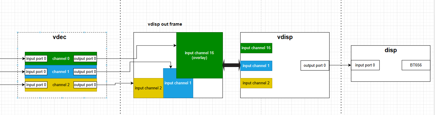
The module MI_VDISP is designed to assemble multiple outputs from front-end module along with user injections as needed to a whole data frame with thumbnail window for each input, and then output it.
A typical scenario of VDISP goes like this:
-
Assuming we have three vdec output channels: green<0>/blue<1>/yellow<2>
-
Binding vdec channel<0> with vdisp input channel< overlay >, vdec channel<1> with vdisp input channel<1>, vdec channel<2> with vdisp input channel<2>. It should be noted that non-overlay channels do not support overlay functionality, while overlay channels can be superimposed onto any other channels, including both normal channels and overlay channels.
-
Binding vdisp output port<0> with disp input port<0>
-
Outputting data frame by BT656
1.2. Base structure
VDISP has two types of channels: non-overlay channels and overlay channels, each with distinct characteristics. The special feature of the non-overlay channel is that the input/output buffer is the same block. This allows previous-stage modules to employ a stride writing method, directly writing data into corresponding positions of the output buffer to achieve the final stitched effect, enabling zero-copy memory operations. The overlay channel, on the other hand, specializes in superposition functionality. It can overlay on top of any other channels, including both non-overlay channels and other overlay channels.
1.3. Function Introduction
-
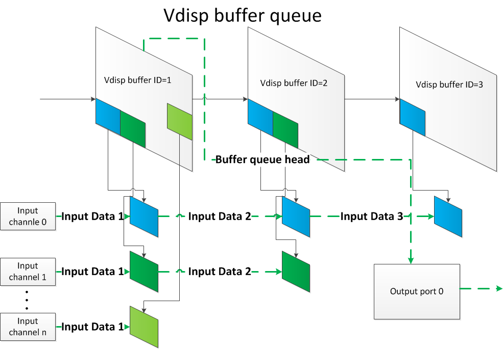
When using Non-overlay input channel, front-end module of VDISP will directly write datas into the output buffer of VIDSP. So, VDISP does not need to copy anything.
-
VDISP supports fixed frame-rate mode and free frame-rate mode. See parameter u32FrmRate of MI_VDISP_OutputPortAttr_t.
-
VDISP supports dynamically modifying properties of input/output port of VDISP.
-
When using overlay input channel, It can be superimpose on other channels, including Non-overlay channel and the other overlay channel.
-
VDISP supports moving the overlay channnel to the top for displaying.
-
Freeze frame will be displayed if the input channel is paused.
-
Currently, VDISP does not support format-conversion/cropping/scaling.
-
Currently, VDISP supports two input data formats:
E_MI_SYS_PIXEL_FRAME_YUV_SEMIPLANAR_420
E_MI_SYS_PIXEL_FRAME_YUV422_YUYV
-
The starting horizontal coordinate of the input channel (u32OutX) has alignment requirements, but the specific alignment value depends on the frontend module connected to VDISP. This is because hardware components usually have address alignment requirements when reading and writing memory; otherwise, it can cause anomalies in the final output, such as borders. If no settings are defined for the current stage, the default alignment will be used, with horizontal stride alignment of 16 and vertical stride alignment of 2. Additionally, the horizontal layer and vertical stride alignment requirements can be modified through modparam, but they must correspond with the alignment of the previous stage.
-
Control of overlay channel layer priority.
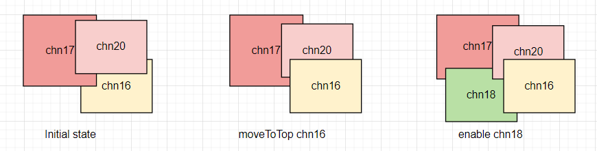
The new enabled channel layer priority is sorted in ascending order based on the size of chnId; the larger the chnId, the higher the layer priority.
Disabling/enabling the channel will not affect the layer priority. After disabling the channel, when re-enabled, it will display according to the layer priority at the time it was disabled.
The channels that have been operated on through the interface MI_VDISP_MoveToTop have a layer priority higher than those that have not undergone this operation, and the channel that last called this interface has the highest layer priority. For example: Currently, there are channels chn16, chn17, and chn20. After performing the MI_VDISP_MoveToTop operation on chn16, the priority order is: chn17, chn20, chn16. If chn18 is enabled at this time, the priority order will be: chn17, chn18, chn20, chn16, with the highest layer priority still being chn16. As shown in the figure below:
-
Please refer to SPECIFICATION for more details.
1.4 Application Scenario
VDISP can be used on pure Linux, pure Rtos and DualOs.
1.5 Chip Difference
There is no difference between the chips, because VDISP is a pure software module.
1.6 Development Process
1.6.1 Compile Setting
-
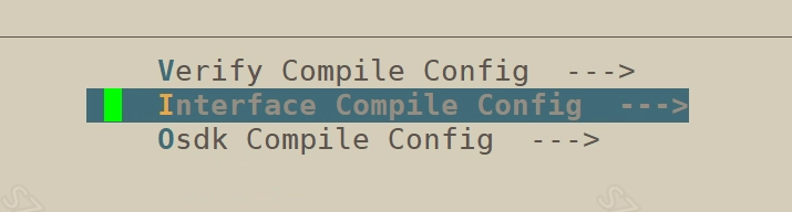
Enter the root directory of alkaid project and perform "make menuconfig"
-
Press Enter to enter "Sdk Config" option

-
Press Enter to enter "Interface Compile Config" option
-
Press Space Key to choose Vdisp and then compile image

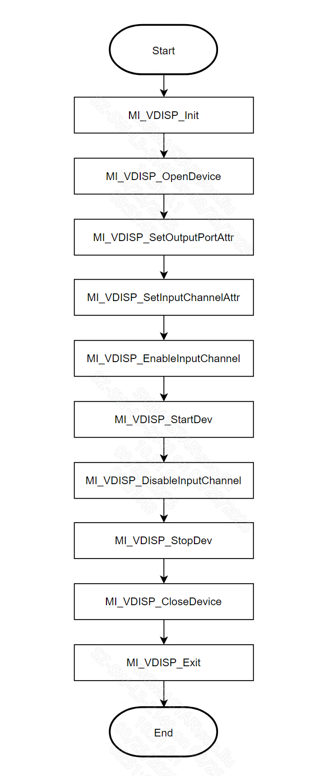
1.6.2 Calling Process
It shows the calling process of VDISP as shown below:
1.7. APPENDIX
This section details an implementation of the scenario described in Summary section.
1.7.1 Flow Chart of Sample
GREEN parts indicate the module vdisp was involved.

1.7.2 Partial Sample Involving vdisp
1.7.2.1. Construct module vdisp
#include <threads.h>
#include <stdio.h>
#include <stdlib.h>
#include <string.h>
#include <unistd.h>
#include <assert.h>
#include <signal.h>

#include <mi_sys_datatype.h>
#include <mi_sys.h>
#include <mi_vdisp_datatype.h>
#include <mi_vdisp.h>

/*
* Initialize module vdisp
*      v
* Open vdisp device
*      v
* Setting parameters of vdisp input channel/output port
*      v
* Activate input channels
*      v
* Start vdisp device
*/
void construct_vdisp_module(void)
{
#define MAKE_YUYV_VALUE(y,u,v)    ((y) << 24) | ((u) << 16) | ((y) << 8) | (v)
#define YUYV_BLACK                MAKE_YUYV_VALUE(0,128,128)
#define ALIGN16_DOWN(x) (x&0xFFF0)

    typedef struct RECT
    {
        /*
        (x,y)_ _ _ _ _
        |             |
        |            (h)
        |_ _ _(w)_ _ _|
        */
        short x;
        short y;
        short w;
        short h;
    } RECT;

    /*
    * Initialize module vdisp
    */
    MI_VDISP_Init();

    MI_VDISP_InputChnAttr_t stInputChnAttr;
    MI_VDISP_OutputPortAttr_t stOutputPortAttr;
    MI_VDISP_DEV DevId = 0;
    RECT rect_0, rect_1, rect_2;
    MI_VDISP_CHN Chn_0_Id = VDISP_OVERLAYINPUTCHNID;
    MI_VDISP_CHN Chn_1_Id = 1;
    MI_VDISP_CHN Chn_2_Id = 2;

    /*
    * open a virtual device of vdisp
    */
    MI_VDISP_OpenDevice(DevId);

    /*
    * align starting horizontal corrdinate by 16
    * setting parameters of input channel
    */
    rect_0.x = ALIGN16_DOWN(960);
    rect_0.y = 0;
    rect_0.w = 960;
    rect_0.h = 960;
    stInputChnAttr.s32IsFreeRun = TRUE;
    stInputChnAttr.u32OutHeight = rect_0.h;
    stInputChnAttr.u32OutWidth = rect_0.w;
    stInputChnAttr.u32OutX = rect_0.x;
    stInputChnAttr.u32OutY = rect_0.y;
    /*
    *setting parameters of input channel<VDISP_OVERLAYINPUTCHNID>
    */
    MI_VDISP_SetInputChannelAttr(DevId, Chn_0_Id, &stInputChnAttr);

    /*
    * align starting horizontal corrdinate by 16
    * setting parameters of input channel
    */
    rect_1.x = ALIGN16_DOWN(0);
    rect_1.y = 1080 - 300;
    rect_1.w = ALIGN16_DOWN(300);
    rect_1.h = 300;
    stInputChnAttr.s32IsFreeRun = TRUE;
    stInputChnAttr.u32OutHeight = rect_1.h;
    stInputChnAttr.u32OutWidth = rect_1.w;
    stInputChnAttr.u32OutX = rect_1.x;
    stInputChnAttr.u32OutY = rect_1.y;
    /*
    *setting parameters of input channel<1>
    */
    MI_VDISP_SetInputChannelAttr(DevId, Chn_1_Id, &stInputChnAttr);

    /*
    * align starting horizontal corrdinate by 16
    * setting parameters of input channel
    */
    rect_2.x = ALIGN16_DOWN(300);
    rect_2.y = 1080 - 700;
    rect_2.w = 700;
    rect_2.h = 700;
    stInputChnAttr.s32IsFreeRun = TRUE;
    stInputChnAttr.u32OutHeight = rect_2.h;
    stInputChnAttr.u32OutWidth = rect_2.w;
    stInputChnAttr.u32OutX = rect_2.x;
    stInputChnAttr.u32OutY = rect_2.y;
    /*
    *setting parameters of input channel<2>
    */
    MI_VDISP_SetInputChannelAttr(DevId, Chn_2_Id, &stInputChnAttr);

    //setting output color format
    stOutputPortAttr.ePixelFormat = E_MI_SYS_PIXEL_FRAME_YUV_SEMIPLANAR_420;
    //setting backgroud color of vdisp's output frame
    stOutputPortAttr.u32BgColor = YUYV_BLACK;
    //setting output framerate
    stOutputPortAttr.u32FrmRate = 30;
    //setting height of output frame
    stOutputPortAttr.u32Height = 1080;
    //setting width of output frame
    stOutputPortAttr.u32Width = 1920;
    //settin initial pts of output frame
    stOutputPortAttr.u64pts = 0;

    /*
    * setting parameters of output port<0>
    */
    MI_VDISP_SetOutputPortAttr(DevId,0,&stOutputPortAttr);

    /*
    * activating input channels <VDISP_OVERLAYINPUTCHNID,1,2>
    */
    MI_VDISP_EnableInputChannel(DevId, Chn_0_Id);
    MI_VDISP_EnableInputChannel(DevId, Chn_1_Id);
    MI_VDISP_EnableInputChannel(DevId, Chn_2_Id);

    /*
    * start vdisp device
    */
    MI_VDISP_StartDev(DevId);
}
1.7.2.2. Binding front/back ends
/*
* binding vdec out0 -> vdisp inOverlay---\
* binding vdec out1 -> vdisp in1 --------\ -> disp in0
* binding vdec out2 -> vdisp in2---------\
*/
void bind_disp_vdisp_vdec(void)
{
    MI_SYS_ChnPort_t stSrcChnPort;
    MI_SYS_ChnPort_t stDstChnPort;

    /*
    * binding vdisp out0-> disp in0
    * <chn,dev,port> : (0,0,0) -> (0,0,0)
    */
    stSrcChnPort.eModId = E_MI_MODULE_ID_VDISP;
    stSrcChnPort.u32ChnId = 0;
    stSrcChnPort.u32DevId = 0;
    stSrcChnPort.u32PortId = 0;

    stDstChnPort.eModId = E_MI_MODULE_ID_DISP;
    stDstChnPort.u32ChnId = 0;
    stDstChnPort.u32DevId = 0;
    stDstChnPort.u32PortId = 0;
    MI_SYS_BindChnPort(&stSrcChnPort, &stDstChnPort, 30, 30);

    /*
    * binding vdec out0-> vdisp inOverlay
    * <chn,dev,port> : (0,0,0) -> (VDISP_OVERLAYINPUTCHNID,0,0)
    */
    stSrcChnPort.eModId = E_MI_MODULE_ID_VDEC;
    stSrcChnPort.u32ChnId = 0;
    stSrcChnPort.u32DevId = 0;
    stSrcChnPort.u32PortId = 0;

    stDstChnPort.eModId = E_MI_MODULE_ID_VDISP;
    stDstChnPort.u32ChnId = VDISP_OVERLAYINPUTCHNID;
    stDstChnPort.u32DevId = 0;
    stDstChnPort.u32PortId = 0;
    MI_SYS_BindChnPort(&stSrcChnPort, &stDstChnPort, 30, 30);

    /*
    * binding vdec out0-> vdisp in1
    * <chn,dev,port> : (1,0,0) -> (1,0,0)
    */
    stSrcChnPort.eModId = E_MI_MODULE_ID_VDEC;
    stSrcChnPort.u32ChnId = 1;
    stSrcChnPort.u32DevId = 0;
    stSrcChnPort.u32PortId = 0;

    stDstChnPort.eModId = E_MI_MODULE_ID_VDISP;
    stDstChnPort.u32ChnId = 1;
    stDstChnPort.u32DevId = 0;
    stDstChnPort.u32PortId = 0;
    MI_SYS_BindChnPort(&stSrcChnPort, &stDstChnPort, 30, 30);

    /*
    * binding vdec out2-> vdisp in2
    * <chn,dev,port> : (2,0,0) -> (2,0,0)
    */
    stSrcChnPort.eModId = E_MI_MODULE_ID_VDEC;
    stSrcChnPort.u32ChnId = 2;
    stSrcChnPort.u32DevId = 0;
    stSrcChnPort.u32PortId = 0;

    stDstChnPort.eModId = E_MI_MODULE_ID_VDISP;
    stDstChnPort.u32ChnId = 2;
    stDstChnPort.u32DevId = 0;
    stDstChnPort.u32PortId = 0;
    MI_SYS_BindChnPort(&stSrcChnPort, &stDstChnPort, 30, 30);

}
1.7.2.3. Unbinding front/back ends
/*
* unbinding vdisp out0 -- disp in0---------\
* unbinding vdec out0 -> vdisp inOverlay---\
* unbinding vdec out1 -> vdisp in1 --------\
* unbinding vdec out2 -> vdisp in2---------\
*/

void unbind_disp_vdisp_vdec(void)
{
    MI_SYS_ChnPort_t stSrcChnPort;
    MI_SYS_ChnPort_t stDstChnPort;

    /*
    * 解绑vdisp out0-> disp in0
    * <chn,dev,port> : (0,0,0) -> (0,0,0)
    */
    stSrcChnPort.eModId = E_MI_MODULE_ID_VDISP;
    stSrcChnPort.u32ChnId = 0;
    stSrcChnPort.u32DevId = 0;
    stSrcChnPort.u32PortId = 0;

    stDstChnPort.eModId = E_MI_MODULE_ID_DISP;
    stDstChnPort.u32ChnId = 0;
    stDstChnPort.u32DevId = 0;
    stDstChnPort.u32PortId = 0;
    MI_SYS_UnBindChnPort(&stSrcChnPort, &stDstChnPort);

    /*
    * 解绑vdec out0-> vdisp inOverlay
    * <chn,dev,port> : (0,0,0) -> (VDISP_OVERLAYINPUTCHNID,0,0)
    */
    stSrcChnPort.eModId = E_MI_MODULE_ID_VDEC;
    stSrcChnPort.u32ChnId = 0;
    stSrcChnPort.u32DevId = 0;
    stSrcChnPort.u32PortId = 0;

    stDstChnPort.eModId = E_MI_MODULE_ID_VDISP;
    stDstChnPort.u32ChnId = VDISP_OVERLAYINPUTCHNID;
    stDstChnPort.u32DevId = 0;
    stDstChnPort.u32PortId = 0;
    MI_SYS_UnBindChnPort(&stSrcChnPort, &stDstChnPort);

    /*
    * 解绑vdec out0-> vdisp in1
    * <chn,dev,port> : (1,0,0) -> (1,0,0)
    */
    stSrcChnPort.eModId = E_MI_MODULE_ID_VDEC;
    stSrcChnPort.u32ChnId = 1;
    stSrcChnPort.u32DevId = 0;
    stSrcChnPort.u32PortId = 0;

    stDstChnPort.eModId = E_MI_MODULE_ID_VDISP;
    stDstChnPort.u32ChnId = 1;
    stDstChnPort.u32DevId = 0;
    stDstChnPort.u32PortId = 0;
    MI_SYS_UnBindChnPort(&stSrcChnPort, &stDstChnPort);

    /*
    * 解绑vdec out2-> vdisp in2
    * <chn,dev,port> : (2,0,0) -> (2,0,0)
    */
    stSrcChnPort.eModId = E_MI_MODULE_ID_VDEC;
    stSrcChnPort.u32ChnId = 2;
    stSrcChnPort.u32DevId = 0;
    stSrcChnPort.u32PortId = 0;

    stDstChnPort.eModId = E_MI_MODULE_ID_VDISP;
    stDstChnPort.u32ChnId = 2;
    stDstChnPort.u32DevId = 0;
    stDstChnPort.u32PortId = 0;
    MI_SYS_UnBindChnPort(&stSrcChnPort, &stDstChnPort);

}
1.7.2.4. Destruct module vdisp
/*
* disable all channels enabled
*      v
* stop vdisp device
*      v
* close vdisp device
*      v
* exit vdisp
*/
void destruct_vdisp_module(void)
{
    MI_VDISP_DEV DevId = 0;
    MI_VDISP_CHN Chn_0_Id = VDISP_OVERLAYINPUTCHNID;
    MI_VDISP_CHN Chn_1_Id = 1;
    MI_VDISP_CHN Chn_2_Id = 2;
/*
    * diable vdisp channels <VDISP_OVERLAYINPUTCHNID,1,2>
    */
    MI_VDISP_DisableInputChannel(DevId, Chn_0_Id);
    MI_VDISP_DisableInputChannel(DevId, Chn_1_Id);
    MI_VDISP_DisableInputChannel(DevId, Chn_2_Id);

/*
    *stop vdisp device
    */
    MI_VDISP_StopDev(DevId);
/*
    *close vdisp device
    */
    MI_VDISP_CloseDevice(DevId);
/*
    *exit vdisp
    */
    MI_VDISP_Exit();
}
2. List of APIs
| Name of API | Function |
|---|---|
| MI_VDISP_Init | Initialize Module |
| MI_VDISP_Exit | De-initialize Module |
| MI_VDISP_OpenDevice | Open a virtual VDISP device |
| MI_VDISP_CloseDevice | Close a virtual VDISP device |
| MI_VDISP_SetOutputPortAttr | Set attributes of output port |
| MI_VDISP_GetOutputPortAttr | Get attributes of output port |
| MI_VDISP_SetInputChannelAttr | Set attributes of input channel |
| MI_VDISP_GetInputChannelAttr | Get attributes of input channel |
| MI_VDISP_EnableInputChannel | Enable an input channel |
| MI_VDISP_DisableInputChannel | Disable an input channel |
| MI_VDISP_StartDev | Start a VDISP device |
| MI_VDISP_StopDev | Stop a VDISP device |
| MI_VDISP_InitDev | Initialize VDISP device |
| MI_VDISP_DeInitDev | De-initialize VDISP device |
| MI_VDISP_PauseInputChannel | Resume output of certain vdisp input channel |
| MI_VDISP_ResumeInputChannel | Freeze output of certain vdisp input channel |
| MI_VDISP_MoveToTop | Put the window of the channel on top |
2.1. MI_VDISP_Init
-
Function
Initialize VDISP module.
-
Syntax
MI_S32 MI_VDISP_ModuleInit(void); -
Return Value
-
Zero: Successful
-
Non-zero: Failed, see error code for details
-
-
Dependency
-
Header: mi_vdisp.h, mi_vdisp_datatype.h
-
Library: libmi_vdisp.a(so)
-
-
Reference
2.2. MI_VDISP_Exit
-
Function
De-initialize VDISP module.
-
Syntax
MI_S32 MI_VDISP_ModuleDeinit(void); -
Return Value
-
Zero: Successful
-
Non-zero: Failed, see error code for details
-
-
Dependency
-
Header: mi_vdisp.h, mi_vdisp_datatype.h
-
Library: libmi_vdisp.a(so)
-
-
Reference
2.3. MI_VDISP_OpenDevice
-
Function
Open a VDISP virtual device.
-
Syntax
MI_S32 MI_VDISP_OpenDevice(MI_VDISP_DEV DevId) -
Parameter
Name Description Input/Output DevId Device ID Input -
Return Value
-
Zero: Successful
-
Non-zero: Failed, see error code for details
-
-
Dependency
-
Header: mi_vdisp.h, mi_vdisp_datatype.h
-
Library: libmi_vdisp.a(so)
-
-
Note
Initialize VDISP before opening a device.
2.4. MI_VDISP_CloseDevice
-
Function
Close a VDISP virtual device.
-
Syntax
MI_S32 MI_VDISP_CloseDevice(MI_VDISP_DEV DevId); -
Parameter
Name Description Input/Output DevId Device ID Input -
Return Value
-
Zero: Successful
-
Non-zero: Failed, see error code for details
-
-
Dependency
-
Header: mi_vdisp.h, mi_vdisp_datatype.h
-
Library: libmi_vdisp.a(so)
-
2.5. MI_VDISP_SetOutputPortAttr
-
Function
Set attributes of output port.
-
Syntax
MI_S32 MI_VDISP_SetOutputPortAttr(MI_VDISP_DEV DevId, MI_VDISP_PORT PortId,MI_VDISP_OutputPortAttr_t *pstOutputPortAttr); -
Parameter
Name Description Input/Output DevId Device ID Input PortId Port ID Input pstOutputPortAttr Pointer to attributes of output port Input -
Return Value
-
Zero: Successful
-
Non-zero: Failed, see error code for details
-
-
Dependency
-
Header: mi_vdisp.h, mi_vdisp_datatype.h
-
Library: libmi_vdisp.a(so)
-
2.6. MI_VDISP_GetOutputPortAttr
-
Function
Get attributes of output port.
-
Syntax
MI_S32 MI_VDISP_GetOutputPortAttr(MI_VDISP_DEV DevId, MI_VDISP_PORT PortId,MI_VDISP_OutputPortAttr_t *pstOutputPortAttr); -
Parameter
Name Description Input/Output DevId Device ID Input PortId Port ID Input pstOutputPortAttr Pointer to attributes of output port Output -
Return Value
-
Zero: Successful
-
Non-zero: Failed, see error code for details
-
-
Dependency
-
Header: mi_vdisp.h, mi_vdisp_datatype.h
-
Library: libmi_vdisp.a(so)
-
2.7. MI_VDISP_SetInputChannelAttr
-
Function
Set attributes of input channel.
-
Syntax
MI_S32 MI_VDISP_SetInputChannelAttr(MI_VDISP_DEV DevId, MI_VDISP_CHN ChnId,MI_VDISP_InputChnAttr_t *pstInputChnAttr); -
Parameter
Name Description Input/Output DevId Device ID Input ChnId Channel Id Input pstInputChntAttr Pointer to attributes of input channel Input -
Return Value
-
Zero: Successful
-
Non-zero: Failed, see error code for details
-
-
Dependency
-
Header: mi_vdisp.h, mi_vdisp_datatype.h
-
Library: libmi_vdisp.a(so)
-
2.8. MI_VDISP_GetInputChannelAttr
-
Function
Get attributes of input channel.
-
Syntax
MI_S32 MI_VDISP_GetInputChannelAttr(MI_VDISP_DEV DevId, MI_VDISP_CHN ChnId,MI_VDISP_InputChnAttr_t *pstInputChnAttr); -
Parameter
Name Description Input/Output DevId Device ID Input ChnId Channel Id Input pstInputChnAttr Pointer to attributes of input channel Output -
Return Value
-
Zero: Successful
-
Non-zero: Failed, see error code for details
-
-
Dependency
-
Header: mi_vdisp.h, mi_vdisp_datatype.h
-
Library: libmi_vdisp.a(so)
-
2.9. MI_VDISP_EnableInputChannel
-
Function
Enable an input channel.
-
Syntax
MI_S32 MI_VDISP_EnableInputChannel(MI_VDISP_DEV DevId, MI_VDISP_CHN ChnId); -
Parameter
Name Description Input/Output DevId Device ID Input ChnId Channel ID Input -
Return Value
-
Zero: Successful
-
Non-zero: Failed, see error code for details
-
-
Dependency
-
Header: mi_vdisp.h, mi_vdisp_datatype.h
-
Library: libmi_vdisp.a(so)
-
2.10. MI_VDISP_DisableInputChannel
-
Function
Disable an input channel.
-
Syntax
MI_S32 MI_VDISP_DisableInputChannel(MI_VDISP_DEV DevId, MI_VDISP_CHN ChnId); -
Parameter
Name Description Input/Output DevId Device ID Input ChnId Channel ID Input -
Return Value
-
Zero: Successful
-
Non-zero: Failed, see error code for details
-
-
Dependency
-
Header: mi_vdisp.h, mi_vdisp_datatype.h
-
Library: libmi_vdisp.a(so)
-
2.11. MI_VDISP_StartDev
-
Function
Start a VDISP device.
-
Syntax
MI_S32 MI_VDISP_StartDev(MI_VDISP_DEV DevId); -
Parameter
Name Description Input/Output DevId Device ID Input -
Return Value
-
Zero: Successful
-
Non-zero: Failed, see error code for details
-
-
Dependency
-
Header: mi_vdisp.h, mi_vdisp_datatype.h
-
Library: libmi_vdisp.a(so)
-
2.12. MI_VDISP_StopDev
-
Function
Stop a VDISP device.
-
Syntax
MI_S32 MI_VDISP_StopDev(MI_VDISP_DEV DevId); -
Parameter
Name Description Input/Output DevId Device ID Input -
Return Value
-
Zero: Successful
-
Non-zero: Failed, see error code for details
-
-
Dependency
-
Header: mi_vdisp.h, mi_vdisp_datatype.h
-
Library: libmi_vdisp.a(so)
-
-
Note
Frame data buffered in VDISP will be cleaned after device is stopped.
2.13. MI_VDISP_InitDev
-
Function
Initialize VDISP device.
-
Syntax
MI_S32 MI_VDISP_InitDev(MI_VDISP_InitParam_t *pstInitParam); -
Parameters
Parameter Name Description Input/Output pstInitParam Initialization Parameter Input -
Return Value
-
Zero: Successful
-
Non-zero: Failed, see error code for details
-
-
Dependency
-
Header: mi_vdisp.h, mi_vdisp_datatype.h
-
Library: libmi_vdisp.a(so)
-
-
Note
-
pstInitParam is unused for now; pass NULL instead.
-
For version 2.07 and above, we recommend using this interface to replace the original MI_VDISP_Init interface.
-
2.14. MI_VDISP_DeInitDev
-
Function
De-initialize VDISP device.
-
Syntax
MI_S32 MI_VDISP_DeInitDev(void); -
Return Value
-
Zero: Successful
-
Non-zero: Failed, see error code for details
-
-
Dependency
-
Header: mi_vdisp.h, mi_vdisp_datatype.h
-
Library: libmi_vdisp.a(so)
-
-
Note
For Version 2.07 and above, we recommend using this interface to replace the original MI_VDISP_Exit interface.
2.15. MI_VDISP_PauseInputChannel
-
Function
Freeze output of certain vdisp input channel.
-
Syntax
MI_S32 MI_VDISP_PauseInputChannel (MI_VDISP_DEV DevId, MI_VDISP_CHN ChnId); -
Parameters
Name Description Input/Output DevId Device ID Input ChnId Channel ID Input -
Return Value
-
Zero: Successful
-
Non-zero: Failed, see error code for details
-
-
Requirement
-
Header: mi_vdisp.h mi_vdisp_datatype.h
-
Library: libmi_vdisp.a(so)
-
-
Note
-
This function call only operates essentially on enabled channels.
-
MI_VDISP_EnableInputChannel can also resume paused channels of vdisp.
-
2.16. MI_VDISP_ResumeInputChannel
-
Function
Resume output of certain vdisp input channel.
-
Syntax
MI_S32 MI_VDISP_ResumeInputChannel (MI_VDISP_DEV DevId, MI_VDISP_CHN ChnId); -
Parameters
Name Description Input/Output DevId Device ID Input ChnId Channel ID Input -
Return Value
-
Zero: Successful
-
Non-zero: Failed, see error code for details
-
-
Requirement
-
Header: mi_vdisp.h mi_vdisp_datatype.h
-
Library: libmi_vdisp.a(so)
-
-
Note
-
This function call only operates essentially on paused channels.
-
MI_VDISP_EnableInputChannel can also resume paused channels of vdisp.
-
2.17. MI_VDISP_MoveToTop
-
Function
Put the window of the channel on top.
-
Syntax
MI_S32 MI_VDISP_MoveToTop(MI_VDISP_DEV DevId, MI_VDISP_CHN ChnId); -
Parameter
Name Description Input/Output DevId The ID of virtual device Input ChnId This parameter specifies the channel id of the window to be topped Input -
Return Value
-
Zero: Successful
-
Non-zero: Failed, see error code for details
-
-
Dependency
-
Header:mi_vdisp.h, mi_vdisp_datatype.h
-
Library:libmi_vdisp.a(so)
-
-
Note
Before calling this function, enable the corresponding input channel using the MI_VDISP_EnableInputChannel.
3. DATA TYPE
Definition of data type in MI VDISP is as listed in the following table:
| Data Type | Description |
|---|---|
| MI_VDISP_DEV | Type of device ID |
| MI_VDISP_PORT | Type of port ID |
| MI_VDISP_CHN | Type of channel ID |
| MI_VDISP_OutputPortAttr_t | Type of output port attributes |
| MI_VDISP_InputChnAttr_t | Type of input channel attributes |
| MI_VDISP_InitParam_t | Type of initialization parameter of VDISP device |
3.1. MI_VDISP_DEV
-
Description
Type of device ID.
-
Definition
typedef MI_S32 MI_VDISP_DEV; -
Note
Valid for natural number.
3.2. MI_VDISP_PORT
-
Description
Type of port ID.
-
Definition
typedef MI_S32 MI_VDISP_PORT; -
Note
Valid for natural number.
3.3. MI_VDISP_CHN
-
Description
Type of channel ID.
-
Definition
typedef MI_S32 MI_VDISP_CHN; -
Note
Valid for natural number.
3.4. MI_VDISP_OutputPortAttr_t
-
Description
Type of output port attributes.
-
Definition
typedef struct MI_VDISP_OutputPortAttr_s { MI_U32 u32BgColor; /* Background color of a output port, in YUV format. [23:16]:v, [15:8]:y, [7:0]:u*/ PIXEL_FORMAT_E ePixelFormat; /* pixel format of a output port */ MI_U64 u64pts; /* current PTS */ MI_U32 u32FrmRate; /* the frame rate of output port */ MI_U32 u32Width; /* the frame width of a output port */ MI_U32 u32Height; /* the frame height of a output port */ } MI_VDISP_OutputPortAttr_t; -
Member
Name Description u32BgColor Background color of output frame, yuv444
[23:16]: v
[15:8]: y
[7:0]: uePixelFormat Pixel format of output frame. u64pts Present PTS of output frame. u32FrmRate Output frame-rate
zero:free frame-rate mode. In this mode, vdisp outputs a frame until front-end module inputs a frame. In other words, the output frame-rate of vdisp is same as the output frame-rate of front-end module
non-zero:fixed frame-rate mode. In this mode, vdisp will output a frame in a fixed time even front-end module does not input a frame.u32Width Width of output frame u32Height Height of output frame
3.5. MI_VDISP_InputChnAttr_t
-
Description
Type of input channel attributes.
-
Definition
typedef struct MI_VDISP_InputPortAttr_s { MI_U32 u32OutX; /* the output frame X position of this input port */ MI_U32 u32OutY; /* the output frame Y position of this input port */ MI_U32 u32OutWidth; /* the output frame width of this input port */ MI_U32 u32OutHeight; /* the output frame height of this input port */ MI_S32 s32IsFreeRun; /* is this port free run */ } MI_VDISP_InputPortAttr_t; -
Member
Name Description u32OutX Coordinate X where thumbnail of input frame will be present in assembled output frame u32OutY Coordinate Y where thumbnail of input frame will be present in assembled output frame u32OutWidth Width for thumbnail of input frame which will be present in the assembled output frame u32OutHeight Height for thumbnail of input frame which will be present in the assembled output frame s32IsFreeRun 0: Input channel’s frame in which PTS smaller than present PTS of output port will be ignored. Other: Input frame will not be checked
3.6. MI_VDISP_InitParam_t
-
Description
VDISP device initialization parameter.
-
Definition
typedef struct MI_VDISP_InitParam_s { MI_U32 u32DevId; MI_U8 *u8Data; } MI_VDISP_InitParam_t; -
Member
Member Description u32DevId Device ID u8Data Data pointer -
Related Data Type and Interface
4. ERROR CODE
The VDISP error codes are as shown in Table 4-1:
| Error Code | Definition | Description |
|---|---|---|
| 0XA00E2000 | MI_SUCCESS | Success |
| 0XA00E2031 | MI_VDISP_ERR_FAIL | Operation failed, please refer to system log |
| 0XA00E2001 | MI_VDISP_ERR_INVALID_DEVID | Illegal device id, please refer to system log |
| 0XA00E2003 | MI_VDISP_ERR_ILLEGAL_PARAM | Illegal parameter, please refer to system log |
| 0XA00E2008 | MI_VDISP_ERR_NOT_SUPPORT | Operation failed, output color format was not supported |
| 0XA00E2022 | MI_VDISP_ERR_MOD_INITED | Operation failed, VDISP module already initialized |
| 0XA00E2021 | MI_VDISP_ERR_MOD_NOT_INIT | Operation failed, VDISP module needs to be initialized |
| 0XA00E2240 | MI_VDISP_ERR_DEV_OPENED | Operation failed, VDISP device already opened |
| 0XA00E2241 | MI_VDISP_ERR_DEV_NOT_OPEN | Operation failed, open VDISP device first |
| 0XA00E2027 | MI_VDISP_ERR_DEV_NOT_STOP | Operation failed, stop VDISP device first |
| 0XA00E2242 | MI_VDISP_ERR_DEV_NOT_CLOSE | Operation failed, close VDISP device first |
| 0XA00E2007 | MI_VDISP_ERR_NOT_CONFIG | Operation failed, configure VDISP output port first |
| 0XA00E2024 | MI_VDISP_ERR_PORT_NOT_DISABLE | Operation failed, disable input channels first |
| 0XA00E2243 | MI_VDISP_ERR_PORT_NOT_UNBIND | Operation failed, unbind input/output first |
| 0XA00E2012 | MI_VDISP_ERR_BUSY | Last change to the vdisp input parameters has not yet taken effect |
5. SPECIFICATION
| Definition | Value | Description |
|---|---|---|
| VDISP_MAX_DEVICE_NUM | 4 | Max virtual device number |
| VDISP_MAX_CHN_NUM_PER_DEV | 16 | Max non-overlay input channel number per device |
| VDISP_MAX_INPUTPORT_NUM | 1 | Max port number of input channel. |
| VDISP_MAX_OVERLAYINPUTCHN_NUM | 48 | Max overlay input channel number per device. Built-in constable value. Rebuilding module is required if more overlay channels are needed. |
| VDISP_OVERLAYINPUTCHNID | VDISP_MAX_CHN_NUM_PER_DEV | Starting ID of overlay input channel |
| VDISP_MAX_OUTPUTPORT_NUM | 1 | Max output port number per device |
6. PROCFS INTRODUCTION
6.1. cat
-
Debug info
-
Debug info analysis
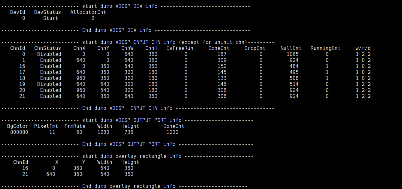
Record VDISP current usage status, device attribute, Input channel attribute, Output port attribute and rectangle attributes after overlay channel cutting, which can be dynamically got to debug and test.
-
Parameter Description
Parameter Description device info DevId Device ID DevStatus Working status of Vdisp: Uninit/ Init/ Start/ Stop AllocatorCnt The number of Allocator created by vdisp input channel info ChnId Channel ID
Value range: [0~63], 0-15 is the normal channel and the others is overlay channel.ChnStatus Port status: Uninit/ Init/ Enabled/ Paused/ Disabled ChnX Input the X starting coordinate address of the inport ChnY Input the Y starting coordinate address of the inport ChnW Input the image width of the inport, which needs to be aligned according to the chip ChnH Input the image height of the inport IsFreeRun Frame rate control or not
0: pts control play
1: free playDoneCnt The number of frame processed successfully by input channel DropCnt The number of frame droped by input channel NullCnt The number of frame not processed by input channel RunningCnt The number of frame runned by input channel w/r/d w/r/d pointer Output port info BgColor Background color, printed here is decimal PixelFmt Color space
Value range: [0~E_MI_SYS_PIXEL_FRAME_FORMAT_MAX-1]
0-YUYV422, 11-YUVSP420FrmRate Output frame rate
zero:free frame-rate mode
non-zero:fixed frame-rate modeWidth Image output width Height Image output height DoneCnt The number of frame processed successfully by vdisp output port Overlay rectangle info ChnId Channel ID
Range of values:[16~63],the further back, the higher the layer priority. As shown in the figure, the priority of chn21 is higher than that of chn16.X The initial X coordinate of overlay rectangle Y The initial Y coordinate of overlay rectangle Width Width of overlay rectangle Height Height of overlay rectangle
6.2. echo
# echo help > /proc/mi_modules/mi_vdisp/mi_vdisp0

Echo help to view available commands.
Table 1-1:
| Function | enable/disable input channel dynamically |
|---|---|
| Command | echo enablechn param1 param2 > /proc/mi_modules/mi_vdisp/mi_vdisp0 |
| Parameter Description | param1: input channel Id param2: [0-1] 0-disable, 1-enable |
| Example | echo enablechn 0 0 > /proc/mi_modules/mi_vdisp/mi_vdisp0 |
Table 1-2:
| Function | start/stop vdisp device dynamically |
|---|---|
| Command | echo startdev param1 > /proc/mi_modules/mi_vdisp/mi_vdisp0 |
| Parameter Description | param1: [0-1] 0-stop, 1-start |
| Example | echo startdev 0 > /proc/mi_modules/mi_vdisp/mi_vdisp0 |
Table 1-3:
| Function | pause/resume input channel dynamically |
|---|---|
| Command | echo pausechn param1 param2 > /proc/mi_modules/mi_vdisp/mi_vdisp0 |
| Parameter Description | param1: input channel Id param2: [0-1] 0-resume, 1-pause |
| Example | echo pausechn 0 1 > /proc/mi_modules/mi_vdisp/mi_vdisp0 |
Table 1-4:
| Function | move overlay channel to the top |
|---|---|
| Command | echo movetotop param1 > /proc/mi_modules/mi_vdisp/mi_vdisp0 |
| Parameter Description | param1: input channel Id, It is noticed that only overlay channel can use this command |
| Example | echo movetotop 16 > /proc/mi_modules/mi_vdisp/mi_vdisp0 |
Table 1-5:
| Function | dump input image |
|---|---|
| Command | echo dumpin param1 param2 param3 param4 > /proc/mi_modules/mi_vdisp/mi_vdisp0 |
| Parameter Description | param1: device Id param2: channel Id param3: path param4: the count of dumped images |
| Example | echo dumpin 0 0 /mnt 10 > /proc/mi_modules/mi_vdisp/mi_vdisp0 |
Table 1-6:
| Function | dump output image |
|---|---|
| Command | echo dumpout param1 param2 param3 > /proc/mi_modules/mi_vdisp/mi_vdisp0 |
| Parameter Description | param1: device Id param2: path param3: the count of dumped images |
| Example | echo dumpout 0 /mnt 10 > /proc/mi_modules/mi_vdisp/mi_vdisp0 |
7. MODPARAM.json Description
7.1. The json file content
"E_MI_MODULE_ID_VDISP" :
{
    "vdisp_bufq_depth": 4,
    "vdisp_outbuf_stride_h": 0,
    "vdisp_outbuf_stride_v": 0
}
The modparam.json is under /config, when sys is initialized, the json file will be loaded.
7.2. VDISP common paramaters and paramater description
| Parameters | Default value | Supported chips | Customer configuration | Function |
|---|---|---|---|---|
| vdisp_bufq_depth | 4 | Maruko, Iford, Ifado, Ifackel | Y | Control the depth of the cached output buffer circular queue. |
| vdisp_outbuf_stride_h | 0 | Maruko, Iford, Ifado, Ifackel | Y | Control the alignment requirements of the output buffer's horizontal stride. |
| vdisp_outbuf_stride_v | 0 | Maruko, Iford, Ifado, Ifackel | Y | Control the alignment requirements of the output buffer's vertical stride. |
7.3. Example of parameter usage
7.3.1. vdisp_bufq_depth
- This parameter controls the depth of the output buffer's circular queue and the maximum number of output tasks it can handle. In application scenarios, when the GetIntoMmaLackCnt parameter value for the front-end output channels corresponding to vdisp normal chn (chn0 - chn15) is relatively large (indicating memory allocation failures due to insufficient memory), increasing this parameter can help resolve memory allocation issues caused by insufficient memory. The larger this parameter, the greater the memory overhead for MMA.
7.3.2. vdisp_outbuf_stride_h
-
This parameter controls the alignment requirements for the horizontal stride of the vdisp output buffer.
-
When set to 0, it will obtain the maximum stride value from the horizontal alignment requirements of the stride corresponding to all normal channels in the previous stage, which will be set as the horizontal stride alignment requirement for the vdisp output buffer. If the alignment requirement values for all the aforementioned channels are 0 (not set in the previous stage), the default value of 16 will be used for alignment.
-
When set to non-zero, this parameter directly sets the alignment requirement for the horizontal stride of the vdisp output buffer.
7.3.3. vdisp_outbuf_stride_v
-
This parameter controls the alignment requirements of the vertical stride of the vdisp output buffer.
-
When set to 0, the maximum stride value will be obtained from the vertical direction stride alignment requirements of all corresponding upstream normal channels, and this will be set as the vertical stride alignment requirement for the vdisp output buffer. If the alignment requirement values of all the aforementioned channels are 0 (not set by the upstream), the default value of 2 will be used for alignment.
-
When set to non-zero, this parameter is directly used to set the vertical stride alignment requirements of the vdisp output buffer.