Alkaid Defconfig
REVISION HISTORY
| Revision No. | Description |
Date |
|---|---|---|
| 1.0 | 02/01/2024 | |
| 1.1 | 05/29/2024 | |
| 1.2 | 06/03/2024 |
1. Overview
1.1. Function Description
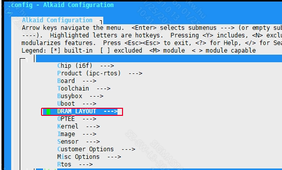
Alkaid defconfig is the top-level configuration file of the entire project compilation environment. The defconfig provides a graphical configuration interface in the form of menuconfig.
In order to display the menuconfig interface, please refer to the environment construction document to set up the toolchain and execute it in the project directory:
sigmastar@ubuntu:~/sourcecode/project/$ make menuconfig

Figure1-1: The Menuconfig Graphical Interface Corresponding to Alkaid Defconfig
The main configuration options of alkaid defconfig are as follows:
1.2. Document Format Constraints
Regular: used for writing the main content of the document, in which code snippets need to be written in a fixed-width font.
Regular + Bold: used for writing important content in the body of the document.
Italic: used for writing the Tips part of the document.
Italic + Bold: used for writing important content in the Tips part of the document.
1.3. Keyword
NVR: Network Video Recorder.
DVR: Digital Video Recorder, or digital hard disk recorder.
XVR: X (representing any one or more functions) Video Recorder. The current SigmaStar implementation is NVR+DVR.
IPC: IP Camera, i.e. network camera.
USBCAM: USB Camera.
CARDV: Car Digital Video.
DISPCAM: Display Camera, i.e. camera screen display.
Android: A free and open source mobile operating system based on the Linux kernel (excluding GNU components).
IPC-RTOS: SigmaStar's self-developed dual system, which can run Linux and RTOS systems at the same time, taking into account the lightweight of RTOS and the powerful scalability of Linux, to realize the characteristics of quick startup.
DualOs: Same as IPC-RTOS.
2. Chip
Chip model series name. Taking the iFord series as an example, this series of chips includes bga1, bga2, qfn128 in combination with different DDRs. This parameter generally does not need to be modified after the bringup stage. To add defconfig, you only need to use the existing model. This parameter affects some resource storage paths in the project directory.
3. Product
Product forms, include IPC, NVR, USBCAM and other different solutions. Different solutions have different default scenarios, so the packaged configuration files and running bins are different. Please use different software solution configurations based on the different product forms used.
4. Board
Development board related software and hardware configuration.
4.1. Development Board Model
The development board model will generally hardly change after it is determined in the bringup stage. It is normal for it to be different from the model named in the defconfig file. This parameter affects some configurations during code compilation. Taking iFord as an example, the ko configuration installed by default at startup exists in:
project/release/chip/${CHIP}/${PRODUCT}/${BOARD}/bootscript/spinand/boot_sequence.mk
If different boards require different configurations, you can refer to the foregoing path to add new configurations.
4.2. Board Name
The full name of the development board model, which generally does not need to be modified. This parameter will affect some configuration scripts used in the image packaging process. Take iFord as an example:
project/board/${CHIP}/${BOARD_NAME}/config/
Some config.json files will be saved in the directory.
If different boards require different configurations, you can refer to the foregoing path to add new configurations.
5. Toolchain
The tool chain configuration is generally determined before bringup and will basically not be modified, unless the chip supports multiple tool chains (when compatibility issues are resolved).
5.1. LinuxArch
The Linux operating architecture is related to the SOC core solution. Currently SigmaStar mainly uses the ARM solution.
5.2. Toolchain
Tool chain solution. SigmaStar currently supports glibc, uclibc, and llvm. Please refer to the environment setup for Toolchain settings. The solution will basically not be modified after being finalized. This parameter affects the release installation path and should be modified with caution. Take iFord as an example:
project/release/chip/${CHIP}/${PRODUCT}/common/${TOOLCHAIN}/${TOOLCHAIN_VERSION}/
This directory will install some pre-compiled libs and products during the compilation process for use in the subsequent image packaging stage.
5.3. Toolchain Version
The software version corresponding to the tool chain solution. Parameter influence is the same as above.
5.4. Toolchain Rel
The tool chain prefix has been determined during bringup and generally does not need to be modified. Take iFord as an example:
CONFIG_TOOLCHAIN_REL="arm-linux-gnueabihf-sigmastar-11.1.0"
This configuration will be used in the makefile to form the full name of gcc for use.
sdk/verify/sample_code/mi_dep.mk
25:TOOLCHAIN_REL := $(CROSS_COMPILE)
26:TOOLCHAIN_VERSION := $(shell $(TOOLCHAIN_REL)gcc -dumpversion)
Since the tool chain path is added to the PATH environment variable during environment setup, we can directly call the corresponding command by name.
$ which  arm-linux-gnueabihf-sigmastar-11.1.0-gcc
/tools/toolchain/gcc-11.1.0-17.1.608-sigmastar-glibc-x86_64_arm-linux-gnueabihf/bin/arm-linux-gnueabihf-sigmastar-11.1.0-gccc
6. Busybox
Busybox uses files that have been compiled and packaged in advance using the toolchain in the environment setup. The storage path of the corresponding file is:
project/image/busybox/busybox-1.17.2.arm-linux-gnueabihf-glibc-sigmastar-11.1.0-dynamic.tar.gz
Users can add and modify busybox according to their own needs. The busybox compressed package will be installed in the corresponding file directory during the Alkaid image packaging process.
7. Uboot
7.1. Uboot Build Config
Uboot configuration file, used to compile the config file of the Uboot. Due to different hardware and software configurations, the development board model needs to be matched. The path corresponding to config is:
boot/configs/
7.2. Uboot Bin Name
uboot bin name, does not need to be modified. This parameter will specify the soft connection of the corresponding img file from the boot directory to the project directory for Alkaid image packaging. When the development board is turned on, IPL will load uboot.bin and decompress it into RAM to run. Therefore, different compression formats of uboot will affect the size of uboot.bin and the decompression speed.
7.3. Uboot Version
The uboot version is determined by the boot directory code version and will not be modified midway. Since different uboot versions use different parameters, some configuration files will use different uboot parameters based on this configuration.
7.4. Uboot DTBO LIST
Android DTBO list. Currently this configuration only supports Opera.
8. OPTEE
OPTEE OS make Option.
OPTEE compilation option for passing make parameters to its makefile.
9. kernel
9.1. Kernel Version
Kernel version, taking Souffle as an example, the kernel version is 5.10. Generally, the kernel version is determined during bringup. If you need to support other versions of the kernel, please submit market requirements.
9.2. Kernel Config
Kernel configuration file, used to compile the config file of the Linux kernel. Due to different hardware and software configurations, the development board model needs to be matched. The path corresponding to config is:
kernel/arch/${ARCH}/configs/
9.3. Kernel Bin Name
kernel bin name, does not need to be modified
10. Image
10.1. Using Customized Image Config
This parameter determines whether to use the customer's own partition configuration. When packaging the image, the customer's own partition configuration file can be found from the following path:
project/image/configs/customize/${IMAGE_CONFIG}
10.2. Image Partition Config
Partition configuration file name. For detailed configuration methods of this file, please refer to System Partition.
The partition configurations will be different depending on different flash types, rootfs types, and whether pm_rtos is used. Please configure the partition configuration file according to your needs.
10.3. IPL File Config
IPL file name, the path of this file is set in the Image Partition Config partition configuration file.
10.4. IPL_CUST File Config
IPL_CUST file name, the path of this file is set in the Image Partition Config partition configuration file.
10.5.IPLX File Config
IPLX file name, which is used only for eMMC flash. The path to this file is set in the Image Partition Config partition configuration file.
10.6. TF-A File Config
TF-A bin file name, the path of this file is set in the Image Partition Config partition configuration file.
10.7. OPTEE File Config
OPTEE bin file name, the path of this file is set in the Image Partition Config partition configuration file. After configuration, optee will be compiled and some dependency files will be packaged into the image during compilation.
10.8. VMM File Config
VMM bin file name, the path of this file is set in the Image Partition Config partition configuration file.
If HYP is selected in LH or HYP of Dualos Type, the correct VMM bin name must be filled in here.
10.9. Flash Size
This configuration will only take effect when the Flash type is NOR. This configuration is currently deprecated.
10.10. EMMC BOOT_PART.bin Backup Support
eMMC boot.bin backup function.
10.11 Support AOV Image
Packing MI modules into dualos as a whole aov image
10.12. pm51 Bin
The name of the pm firmware, currently used only by Opera. This configuration takes effect during the image packaging process, and the file path is configured in the corresponding file of Image Partition Config.
10.13. riscvfw Bin
The name of the riscv firmware, currently used only by Opera. This configuration takes effect during the image packaging process, and the file path is configured in the corresponding file of Image Partition Config.
10.14. USB_UPGRADE_IPL_CONFIG
The name of IPL used to make usb factory upgrade image.
10.15. USB_UPGRADE_UBOOT_CONFIG
The name of uboot used to make usb factory upgrade image.
10.16. dla firmware list
This parameter configures the firmware file list copied to the misc/config partition for use by DLA during the image packaging process.
11. Sensor
11.1. IQ
The IQ bin that needs to be packaged is under the path project/board/${CHIP}/iqfile/. The file will be installed in the misc/iqfile directory.
11.2. Sensor List
List of sensor drivers installed in the image by default. The ko file in the list will be automatically insmodded when booting.
There is no need to configure this parameter when using dualos.
11.3. Sensor0 Opt
Set the insmod parameter for the ko corresponding to Sensor0.
There is no need to configure this parameter when using dualos.
11.4. IQ API Bin List
Pack the iq file from project/board/${CHIP}/iqfile/${IQ_API_LIST} to image.
12. Customer_Options
12.1. Mi Dbg
This parameter determines whether to compile mi debug log by default. It takes effect when mi ko/lib is compiled. Turning it off can reduce the code size, but it would be inconvenient to locate the problem if something goes wrong, so this parameter is turned on by default.
12.2. Yuv420/nv21 data is max align uv height to 16
This parameter forces yuv420/nv21 data to do upward 16-byte alignment. It takes effect when mi ko/lib is compiled.
12.3. MI suspend to RAM and standby
Allows content to be saved in power-free memory in sleep mode, called STR.
12.4. MI runtime pm core functionality
Allows the mi module to automatically enter the low power mode to save power when it is idle, which is called runtime pm.
12.5. Merge all mi modules to a sstar_mi.ko
All mi modules are integrated into one sstar_mi.ko to save memory.
12.6. DEBUG_MODPARAM
This parameter determines whether to use the debug version of modparam.json when packaging images. Default is no.
12.7. PROC DEBUG
The mi layer proc debug function, after being enabled, can catenate some debug information through the node of the corresponding module. When disabled, no information will be catenated.
12.8. OVERDRIVE
Th idac voltage ctrl value, and 0 stands for LD, 1 stands for NOD,2 stands for OD,3 stands for idac off.
13. Misc_Options
Miscellaneous function configuration.
13.1. Fpga Pz1 Bench
Used to mark the internal chip development stage in which deconfig is located.
13.2. TFTP Download Addr
The buffer address of the file when performing TFTP download in uboot. The default value is 0x21000000.
13.3. Kernel Boot Addr
The startup address of the kernel, the default value is 0x23000000. This item works on uboot, so loading kernel/boot kernel directly through IPL is not controlled by this item. In other words, this item is invalid for DualOs.
13.4. Init Ramfs Addr
The starting address of the memory where Ramfs is located. Rootfs will be mounted at this address when the kernel starts. The default value is 0x21800000.
13.5. Split Each File Size
Split into larger partition bins to avoid using too large memory during burning and thus stepping on subsequent memory data. The default value is 0x2000000.
13.6. upgrade_type
The firmware upgrade method affects the automatic burning command when entering uboot.
13.7. which mmc device is the SD upgrade card
MMC device number used for SD upgrade. This configuration only takes effect when upgrade_type is configured as sd.
13.8 kernel module list that only packs into image but not insmod
customized kernel module list that only packs into image but not insmod in demo.sh, so that it can be easy to add ko just for debug.
13.9 customized linux modparam.json files
customized purelinux's modparam.json files,it should be put into board/$(CHIP)/json/$(PRODUCT)/ dir.
13.10 customized dualos or rtos modparam.json files
customized modparam.json files of dualos or rtos,it should be put into board/$(CHIP)/json/$(PRODUCT)/ dir.
13.11 wifi config
The ko driver corresponding to the Wi-Fi used is installed by default. If the product concerned does not require Wi-Fi, you can simply ignore this parameter.
13.12 ADB
Android platform adb debugging tool packaging option. This option takes effect during the image packaging phase. Currently this configuration only supports Opera.
13.13 SSH
SSH tool packaging options. This option takes effect during the image packaging phase. Currently this configuration only supports opera.
13.14. BOOTLOGO
BOOTLOGO enable option. This option is currently used in Opera to configure bootcmd, and the chip after iford is used to package the configuration files and images required for the bootlogo.
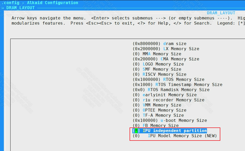
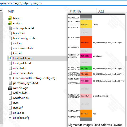
14. DRAM_LAYOUT
14.1. RunTime Moudle Size
alkaid defconfig adjust runtime module's size
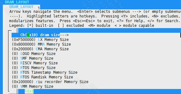
After checking the IPU independent partition, the IPU Model Memory Size can be configured
make defconfig will generate dram_layout.txt in project\configs
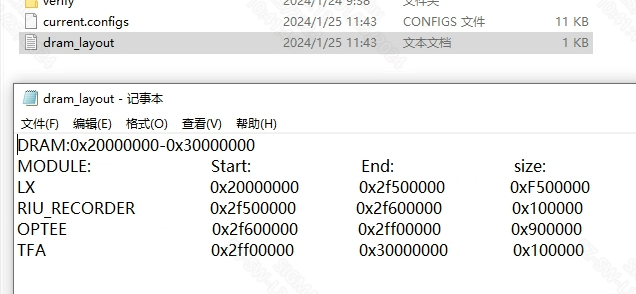
make image will check runtime module's load addr overlap. Then you can get the result of images layout by the load_addr.svg in project\image\output\images
15. RTOS
15.1. Rtos enable
When enabled, RTOS compilation is enabled. This configuration takes effect during compilation and packaging periods.
Pure Linux system does not need to configure this; please make sure that all functions are turned off.
15.1.1. RtosType
When RTOS compilation is turned on, you can select the type of compilation and packaging system. Currently, pure rtos and dualos are supported. This configuration takes effect during compilation and packaging periods.
15.1.2. LH or HYP of Dualos Type
When RtosType is selected as dualos, the Dualos solution needs to be configured. Currently, SigmaStar supports two solutions: light SMPLH (LH) and hypervisor (HYP). This configuration takes effect during compilation and packaging periods.
15.1.3. Rtos build toolchain
The tool chain used to compile Rtos is consistent with the environment construction. This configuration takes effect during compilation and packaging periods.
15.1.4. Rtos build config
The name of the config file used to compile Rtos. This file is located in the rtos directory. This configuration takes effect during compilation and packaging periods.
15.1.5 RTOS Master HW core ID
Specifies which physical core the RTOS runs on.
15.1.6. Fast Demo
This parameter determines whether to package fast demo related files and run them automatically after booting. This parameter takes effect during the image packaging process.
15.1.7. Sensor Type
Sensor model. This parameter will copy the Sensor-related resource files to the partition directory corresponding to the image during the packaging process. For example:
cp -rf $(PROJ_ROOT)/board/$(CHIP)/iqfile/$(SENSOR_TYPE)/$(SENSOR_TYPE)_api.xml $(miscL$(RESOURCE))
15.1.8. RTOS Bin
The name of rtos image, default rtos.sz.
15.1.9 Earlyinit Options
earlyinit options menu.
15.1.9.1 Set Earlyinit Setting Default Json Name
Set the name of the json file to be converted to the header, and it will be selected as default earlyinit setting.
15.1.9.2 Set Earlyinit Setting Built-in Json Name List
Set the json name list that will be converted into header file, separated by spaces.
bootargs_rtos add earlyinit_json=$(your_json_name), where $(your_json_name) is the corresponding json name.
15.1.9.3 Support Dynamically Load Earlyinit Setting From File System
Decide whether to read json from the file system to update earlyinit setting, that means modification of /misc/earlyinit_setting.json will take effect after reboot.
15.2. Rtos use application
The name of the app that runs automatically after Rtos is turned on. This parameter configures the files copied to the misc/miscL partition during the image packaging process.
When both Support IPC application and Support pipeline tree application are selected, you can choose to turn off the Support pipeline tree application to reduce code size.
15.3. Preload Setting file
This parameter configures the configuration files copied to the misc/miscL partition during the image packaging process. It takes effect together with Rtos use application.
if [ "$(CONFIG_RTOS_APPLICATION)" = "rtos_preload" ]; then \
   cp $(PROJ_ROOT)/board/rtos/$(PRELOAD_FILE) $(misc$(RESOURCE))/PreloadSetting.txt ; \
fi;\
if [ "$(CONFIG_RTOS_APPLICATION)" = "pipeline_tree" ]; then \
   cp $(PROJ_ROOT)/../sdk/ptree/preload/resource/$(PRELOAD_FILE) $(misc$(RESOURCE))/ptree.json ; \
fi;\
15.4. ipl earlyinit enable
Enable the earlyinit function of ipl.
16. pm_rtos
pm_rtos is configured for chips with cm4 hardware, which is another set of software and hardware architecture independent of ARM.
16.1. pm_rtos enable
pm_rtos function enable configuration. This configuration takes effect during compilation and packaging periods.
16.2. pm_rtos Bin
The pm_rtos Bin name copied during the image packaging process. This configuration takes effect during the image packaging process, and the file path is configured in the corresponding file of Image Partition Config.
16.3. pm_rtos build toolchain
For the toolchain used to compile pm_rtos, please refer to the environment setup. This configuration takes effect during the compilation period.
16.4. pm_rtos build config
The name of the config file used to compile pm_rtos. This configuration takes effect during the compilation period.
17. Sdk_Config
sdk directory compilation configuration.
17.1. Verify Compile Config
sdk/verify directory compilation configuration.
17.1.1. mi_demo
Whether to compile and package the contents of the mi_demo directory. mi_demo is the application and configuration file related to MI internal module ut testing.
17.1.2. amigos
Whether to compile and package the contents of the amigos directory. amigos is the project directory of the mixer software. Mixer is a set of abstract modular software running and testing frameworks developed by SigmaStar that can dynamically create and modify pipelines.
17.1.3. pipeline_tree
Pipeline Tree (ptree), as the name suggests, is a software framework that abstracts Pipeline into a tree in a data structure. Through the construction and traversal of the tree, the initialization and de-initialization functions of the Pipeline can be realized, thereby achieving the purpose of Pipeline outflow.
17.1.4. sample_code
Whether to compile and package the contents of the sample_code directory. sample_code is a set of open source scenario demonstration projects provided by SigmaStar to customers.
17.1.5. bsp_demo
Whether to compile and package the contents of the bsp_demo directory. bsp_demo is a testing framework within SigmaStar for automated testing of each module of bsp.
17.1.6.cardv_impl
Whether to compile and package the contents of the Cardvimpl directory. Cardvimpl is a cardv backend demo application provided by SigmaStar to customers.
17.1.7. cardv_ui
Whether to compile and package the contents of the CardvUI directory. CardvUI is a cardv ui demo application provided by SigmaStar to customers.
17.2. Interface Compile Config
MI related compilation configuration. It only takes effect when the sdk/interface directory exists. All configurations in this directory take effect during compilation, so the following items are not explained separately.
17.2.1. MI debug level for code size verify config
Some compilation configurations that affect code size.
17.2.1.1. Valid mi log level
Select the log level to be compiled.
17.2.1.2. MI USER LIB OPTIMAZITION
The code optimization level passed to the compiler when user lib is compiled.
17.2.1.3. enable mi kapi for mi interface called from kernel space
Compile the kapi corresponding to the mi user api. These kapi interface functions and parameters are consistent with the user api. However, the kapi is called by the user in kernel mode, so ko will export some more symbols during compilation, which will increase the code szie to a certain extent.
17.2.1.4. enable mi log _FUNCTION_ info
Allow function names to be printed in the log.
17.2.1.5. enable mi log _FILE_ info
Allow the log to print the file where it is located.
17.2.2. aio
Compilation configuration related to audio compilation. If the ai or ao module is enabled, aio will be enabled by default.
17.2.3. vcodec
Codec related compilation configuration. This option is enabled by default when the venc or vdec module is enabled.
17.2.3.1. mhal_vcodec
The core function of the codec driver. If you want to use venc or vdec, this option must be turned on.
17.2.3.2. mhal_neon
MHAL Neon support; chip no longer relies on this option after iFord.
17.2.4. ai
Audio in module compilation switch. The product of the compilation is mi_ai.ko.
17.2.5. ao
Audio out module compilation switch. The product of the compilation is mi_ao.ko.
17.2.6. cipher
Cpher module for encryption and decryption.
17.2.7. common
The mi common module provides some public function support for other mi modules. All mi ko must be installed after this module.
17.2.7.1. mi_common
This module provides an interface for user-level calls. This option is enabled by default after enabling common.
17.2.7.2. mhal_cmdq
The cmdq is SigmaStar's own set of register synchronization services, which provides register settings and synchronization interfaces for all mi modules. If you need to use the mi module, this option must be turned on.
17.2.7.3. cjson write
Support module internal cJSON write, for generating JSON files.
17.2.8. cus3a
The cus3a algorithm module. Users can develop their own AWB/AE/AF algorithm libraries and connect to ISP by registering the AWB/AE/AF Interface. After this module is disabled, the ISP can no longer use the related functions of this module.
17.2.9. debug
The mi_debug.ko compilation switch. For function settings, please refer to: PROC_DEBUG.
17.2.10. disp
DISP is a video display unit whose main function is to perform hardware collage on the image output by the front-end, perform color space conversion on the image after the hardware collage, and finally output it to the monitor or LCD through HDMI/VGA/MIPI/TTL and other interfaces. This module relies on the mhal_disp function, so it will be enabled by force. The disp function provides functional support for internal modules. The mi fb module relies on the disp function, so disp will be force-enabled when mi fb is enabled. The mi disp provides an interface for user-level calls.
17.2.11. divp
DIVP supports preprocessing of an input image, such as cropping, image pixel format conversion, rotation, mirroring, etc., and then scaling each channel separately, and finally outputs images with multiple different resolutions.
iFord does not support this module. Please use the scl module.
17.2.12. gfx
GFX (Graphic Engine) hardware provides fast graphics drawing functions for drawing UI, mainly including rectangular color filling and bitmap moving (supporting scaling, rotation, mirror flipping, format conversion, alpha mixing and overlay, Color Key and other operations). Currently, only Taiyaki, Takoyaki, Tiramisu, Ikayaki, Muffin, and Mochi series chips support GFX. The mi gfx module provides a user interface, and the compiled product is mi_gfx.ko.
17.2.13. hdmi
HDMI (High Definition Multimedia Interface) is a fully digital video and sound transmission interface that can send uncompressed audio and video signals at the same time.
HDMI can be divided into TX end and RX end. TX is the soure device, which is used to transmit data to RX (sink device). This module currently only supports HDMITx based on HDMI ver1.4. The mi hdmi module provides the user layer with the operation interface of the module.
17.2.14. ipu
The MI IPU module accelerates the deduction function of the AI model. It supports the deduction of multiple AI models through channels, the allocation of input/output Tensors within the module, and also the direct use of the previous-level module out buffer as the input Tensor.
17.2.15. iqserver
IQSERVER (Image Quality tuning Server) is used to complete data communication between the tuning tool (IQTool) and the development board, including ISP parameter settings, image acquisition, uploading/downloading related files and other functions.
17.2.16. isp
Image Signal Processing realizes HDR, 3D/2D noise reduction, 3A algorithm, WDR and other related functions. The compilation of this module depends on both vif and sensor modules. ISP sub-options are fully enabled by default..
17.2.17. ispalgo
The isp algorithm module provides an interface for users. This module depends on the isp module.
17.2.18. ive
IVE (Intelligent Video Engine) is a hardware acceleration module in the processing chip intelligent analysis system.
17.2.19. jpd
The JPD decoding module provides functions such as creating decoding channels, controlling decoding, and transmitting code streams. mhal_jpd is enabled by default when jpd is enabled. mi_jpd provides an interface for user-level calls.
17.2.20. ldc
Lens distortion correction module currently supports functions including lens distortion correction, projection transformation mapping function, image splicing, image splicing area fusion, anti-shake function and look-up table function. When ldc is enabled, mhal_ldc is enabled by default. mi_ldc provides an interface for user-level calls.
17.2.20.1. mhal_dis
The dis anti-shake function. This function is not supported under dualos system. Under pure Linux, this function can be turned on and off according to user needs.
17.2.20.1.1. mhal_dis_gme
This is a function based on gme image motion estimation algorithm, which can be turned on as needed.
17.2.20.1.2. mhal_dis_gyro
Dis function based on gyro hardware gyroscope, which can be turned on as needed. To use the dis function, choose at least one of this function and mhal_dis_gme.
17.2.20.2. mhal_multiband
Stitch splicing function is not supported under dualos system. Under pure Linux, this function can be turned on and off according to user needs.
17.2.21. mipitx
Send the Dram data through the MIPI interface protocol. mi_mipitx provides an interface for user-level calls.
17.2.22. rgn
The area management module participates in the internal stream processing of the SCL module. The underlying hardware module supports GOP (Graphic output path). The area management module is a set of software interfaces abstracted using the characteristics of GOP, and uses the principle of time-sharing multiplexing to attach OSD (On-screen display) or Cover to each channel.
The fb functionality depends on this module. mhal_rgn is enabled by default when this module is enabled. mi_rgn provides an interface for user-level calls.
17.2.22.1. sw_osd
When the number of OSDs exceeds the number of gwins, the OSDs that are close together will be automatically grouped together to display more OSDs (128) on the same channel. The OSDs can be closed individually.
17.2.22.2. cover_map
Polygon cover function. It needs to be turned on when using polygon cover on the iFord chip. In other cases, it can be turned off separately.
17.2.23. sed
SED (Smart Encoder) mainly provides functions such as the creation and destruction of intelligent encoding channels, starting and stopping detection of source images, calculating results and associating them to specified encoding channels.
17.2.24. sensor
The SNR (sensor) module implements functions such as obtaining camera interface information, adjusting resolution and frame rate, etc. isp depends on this module. This module is interdependent with vif. mi_sensor provides an interface for user-level calls.
17.2.24.1. mhal_sensorif
The sensor interface function of the mhal layer, the sensor depends on this function. Enabled by default.
17.2.24.2. mhal_csi
This is also the basic function of the sensor and is enabled by default. When enabled, it can support the MIPI sensor streaming function.
17.2.24.3. mhal_lvds
Sensor LVDS interface related functions. If you do not need the LVDS interface, you can turn off this item separately.
17.2.24.4. mhal_earlyinit
The function added for quick startup in dualos scenario is enabled together with mhal_ipl_earlyinit.
17.2.24.5. mhal_ipl_earlyinit
The function added for quick startup in dualos scenario is enabled together with mhal_earlyinit.
17.2.25. shadow
The vdf module relies on this module to complete some kernel mode functions. If the vdf module function is not used, this module can also be turned off.
17.2.26. sys
MI_SYS is the basic module of the entire MI system, which provides a basic environment for the operation of other MI modules.
17.2.27. sys_earlyinit
This module provides environment and functional support in the dualos fast startup scenario. For pure Linux, this option can be turned off.
17.2.28. vdec
vdec is a video decoding module that provides functions such as decoding channel creation, code stream transmission and control, and output image cropping and scaling. This module is required in NVR/XVR scenarios and generally not in IPC scenarios.
17.2.29. vdf
VDF implements functions such as initialization of MD, OD, and VG video channels, channel management, management of video detection results, and channel destruction. This module depends on the shadow module.
17.2.30. vdisp
The VDISP (virtual display) module is designed to combine multiple YUV/RGB color space data into one full-frame output, and designate a thumbnail display window for each data input. Certain thumbnail windows support area overlap.
17.2.31. venc
The video encoder module mainly provides functions such as creating and destroying video encoding channels, starting and stopping receiving images, setting and getting encoding channel attributes, and getting and releasing code streams. This module depends on the vcode module.
17.2.32. vif
Video input (video interface) enables functions such as enabling video input devices, video input channels, and binding video input channels. Both isp and sensor modules depend on this module. The vif sub-options need to be enabled by default.. The mhal_vif log level and mhal_ispscl_log_level can be adjusted according to actual needs.
17.2.33. scl
SCL scales the original picture to the resolution specified by each output port. Each SCL is divided into different Devices according to the type of input data source. Each output port has crop/scaling/mirror/flip/pixel conversion functions. SCL relies on the mhal_vpe function, and mi_scl provides an interface for user-level calls.
17.2.34. wlan
Wireless LAN (WLAN) provides simple scanning of Wi-Fi signals. The connection function provides support for AP and STA modes.
17.2.35. pcie
PCIe (Peripheral component interconnect express) is a universal high-speed serial bus interface standard that is widely used in various fields such as PCs, handheld devices, and industry. MI_PCIE has the characteristics of MI channel (channel) and device (device). By binding other MI modules to the channels of the MI_PCIE module, the data flow inside the MI can be transmitted to other SOCs through PCIe bus communication.
MI_PCIE also provides an interface for the user layer to directly operate the PCIe bus DMA for the transmission of user-defined data types, and provides a set of message synchronization mechanisms based on the PCIe bus, called RPMSG. Message synchronization combined with the PCIe bus DMA allows users to expand the PCIe-based transmission protocol. Currently it is only supported by the Muffin platform.
17.2.36. dsp
Digital signal processing module, currently only supported by the Muffin platform.
17.2.37. dpu
The DPU performs specific algorithm processing on the left and right images input by multiple pairs of cameras, and then outputs depth information corresponding to the input images. Based on the depth information, the distance of the object in the image relative to the camera can be obtained by calculation.
17.2.38. dummy
The dummy module implements a simple workflow of copying inputBuf to outputBuf. The user can inject its outputBuf to the inputPort of the next-level module using the sys interface. Since dummy belongs to the mi module, it also supports mi proc to view debug information, which allows the user to conveniently control buffer and frame rate information. The side effect is that bandwidth consumption will be increased due to the copy operations.
17.2.39. fb
MI_FB is a graphics layer device driver implemented based on Linux Framebuff. It abstracts the display buffer, shields the underlying differences in image hardware, and allows upper-layer applications to directly read and write the display buffer in graphics mode. Users do not need to care about the specific location and storage method of the physical display buffer. These are all handled by MI_FB Module driver. On the basis of providing the basic functions of Linux Framebuff, MI_FB also provides some extended functions, such as inter-layer Alpha, ColorKey, setting display area, etc. MI_FB relies on the mhal_rgn function.
17.2.39.1. disp_path
MI_FB UI supports being directly superimposed on the DISP module. Only chips with GOP hardware in DISP support this path setting. The disp_path depends on the disp module. It can be turned off individually according to user needs to save code size.
17.2.39.2. video_path
MI_FB UI supports overlaying on modules that OSD can attach through the MI_RGN module. The video_path depends on the rgn module. It can be turned off individually according to user needs to save code size.
17.2.40. nir
In a low-light environment, visible light images retain the color information of the image, but have a poor signal-to-noise ratio and serious loss of details; infrared images have a relatively high signal-to-noise ratio and good detail performance, but lose the color information of the image.
The NIR module fuses the above-mentioned visible light images and infrared images to retain color information while improving image details and signal-to-noise ratio, thereby improving image quality in low-light environments.
NIR depends on the mhal_nir function, and mi_nir provides an interface for user-level calls.
17.2.41. hvp
The main purpose of HVP is to access HDMIRX video data. After simple scaling, cropping and frame rate conversion, it is passed backward to DISP or SCL; the frame rate changes by controlling the buffer depth accessed by the internal DMA. The operating modes currently supported include frame mode and realtime mode. In realtime mode, data does not go through internal DMA and frame rate control cannot be performed. HVP depends on the mhal_hvp function, and mi_hvp provides an interface for user-level calls. This function is currently only suppported by Opera.
17.2.42. pspi
This function obtains image data from the sensor through PSPI, or transfers image data to the panel through PSPI. PSPI depends on the mhal_pspi function, and mi_pspi provides an interface for user-level calls.
17.2.43. hdmirx
HDMI is divided into RX end and TX end. The TX end is the source device, which is used to transmit data to RX device (Sink device). The RX end is the receiving end, receiving the HDMI signal sent from the TX end.
17.3. Osdk Compile Config
Open Source SDK compilation options.
17.3.1. drm
The DRM module is a display framework natively supported by Linux. The DRM module replaces the DISP module on Opera. DRM relies on the mahl_rgn and mhal_disp functions. If you need to implement the hdmirx function, you need to turn on the mhal_hdmitx option to enable the function. This function is currently only supported by Opera.
17.3.2. gles_ldc
The LDC distortion correction module implemented based on OpenGLES. This function is currently only suppported by Opera.
18. Android_Ndk
Android compilation environment configuration. Currently this configuration only supports Opera.
18.1. NDK API Version
Android NDK API version.
18.2. NDK Clang Version
The Clang compiler version used by the Android NDK.
18.2.1. NDK Clang Target
Android NDK compilation target platform.
18.2.2. NDK Binutils Prefix
Android NDK compilation tool prefix.
19. SECURE_BOOT
Secure boot related configurations.
19.1. SECURE_BOOT
The specific algorithm chosen for the Secure Boot implementation. This option takes effect when the image is compiled.
19.1.1. IMAGE_AES_DETAILS
Image aes configuration during secure boot. This option only takes effect when aes-related algorithms are selected in SECURE_BOOT. This option takes effect when the image is compiled.
19.1.2. Secureboot_debugmode
Secure boot debug mode. Some information will be added to the printed information. This option takes effect when the image is compiled.
19.2. IPL_With_AES
IPL AES encryption option.
19.2.1. IPL_ENCRYPT
This option determines whether to encrypt IPL or not. This option takes effect when the IPL is compiled.