MI Sensor to SPI Panel Display User Guide
1. Feature Introduction
This demo mainly demonstrates how to display image data collected from the sensor on an SPI screen in real-time after processing through VIF, ISP, and SCL modules.
  +--------+      +--------+      +--------+      +------------+
  |   VIF  | ---> |   ISP  | ---> |   SCL  | ---> | SPI Panel  |
  +--------+      +--------+      +--------+      +------------+
- Implements a complete pipeline from sensor to SPI screen. VIF receives sensor data, ISP performs image processing, SCL performs scaling, and finally displays on SPI screen
- Supports single sensor real-time display scenario. VIF connects to sensor pad0, ISP/SCL uses dev0 chn0
- Binding mode: VIF->ISP->SCL in realtime mode, SCL outputs to SPI panel for display
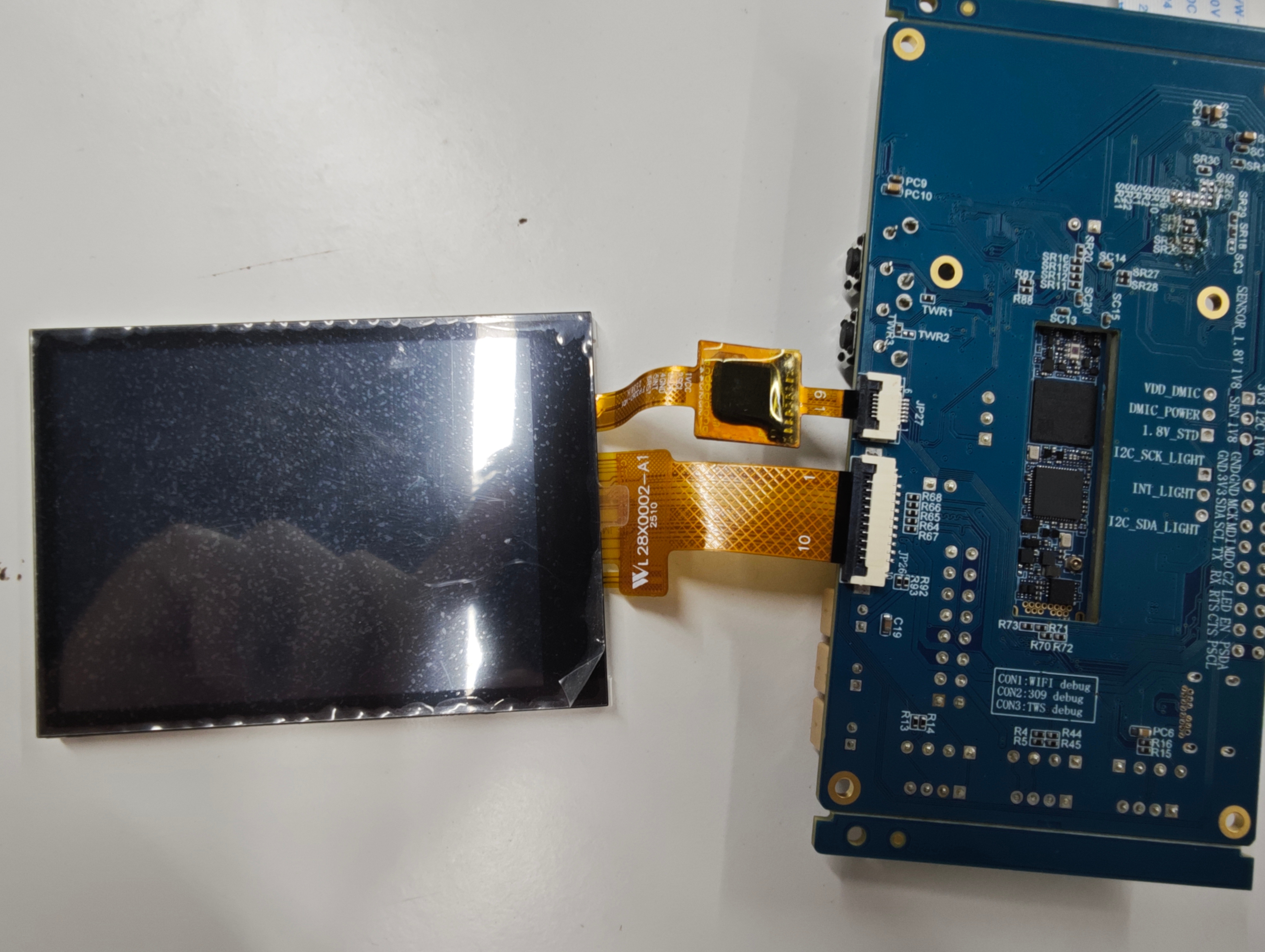
- Display specifications: SPI screen resolution 240x320, frame rate 20fps
- Supports 3DNR function, which can be enabled via parameters
- Supports debug mode, can save raw data files and detailed logs
- When character "q" is entered, the process exits
2. Compilation Environment Instructions
Note
Generally, the corresponding programs are already packaged on the board by default, so compiling sample_code programs is not mandatory. You can directly find prog_sensor2spipanel in the /customer/sample_code/bin folder on the board. If you cannot find the file or have requirements to modify the program, please refer to the following steps.
-
If you cannot find
prog_sensor2spipanel, you can check whetherAPP_REL_PREFIX:= binis included in\sdk\verify\sample_code\source\iford\disp\sensor2spipanel\sensor2spipanel.mk. If not, you can add it to sensor2spipanel.mk, so it will be packaged into the image when compiling the project; -
Select defconfig for full package compilation in the project path according to the board (nand/nor, ddr model, etc.)
For example, for Comake PI D2 model board, using emmc configuration, use the following defconfig. For other board models, please refer to the user manual
ipc_iford.emmc.glibc-11.1.0-ext4fs.ssc029d.256.bga8_lpddr4x_d2_full_defconfigExecute the following commands in the project directory to compile;
export PATH=/tools/toolchain/gcc-sigmastar-9.1.0-2019.11-x86_64_arm-eabi/bin:/tools/toolchain/gcc-11.1.0-20210608-sigmastar-glibc-x86_64_arm-linux-gnueabihf/bin:$PATHexport CROSS_COMPILE=arm-linux-gnueabihf-export ARCH=armmake ipc_iford.emmc.glibc-11.1.0-ext4fs.ssc029d.256.bga8_lpddr4x_d2_full_defconfigmake clean && make image -j8 -
If you need to modify the program, you can cd to the
sdk/verify/sample_codedirectory and executemake clean && make source/iford/disp/sensor2spipanelto compile; -
Get the executable file from
sample_code/out/arm/app/prog_sensor2spipanel; -
Place the executable file
prog_sensor2spipanelon the board at/customer/sample_code/binpath and modify permissions to 777.
3. Runtime Environment Instructions
The runtime environment configuration here is exactly the same as the point sensor program. For details, please refer to Point Sensor Program Instructions 3.1 Single Sensor Runtime Environment Instructions
Hardware Configuration Requirements:
- Used on Comake-D2 model board
- There are two ways to connect single Sensor. One is the default SJ5 IMX681 SENSOR, the other is SJ6 connected to IMX681 SENSOR. Using SJ6/SJ1 requires hardware modification
- At the same time, SPI screen module needs to be connected at JP26
DTS Configuration:
- For Comake-D2 model board, using the defconfig corresponding to scenario 1, the default dts is already configured and does not need to be modified
- SPI screen related dts configuration is already configured by default and does not need to be modified
4. Resource File Instructions
- IQ file location:
/config/iqfile/directory - Default loading: If iqbin parameter is not specified,
/config/iqfile/{sensorname}_api.binfile is loaded by default - Optional files: IQ bin files for some sensors can be obtained from
/project/board/iford/iqfilepath - Calibration data: If 3DNR function needs to be enabled, calibration data path can be specified via calidata parameter
5. Runtime Instructions
cd to the board's /customer/sample_code/bin path and run prog_sensor2spipanel
Parameter explanation:
prog_sensor2spipanel [index] [iqbin] [3dnr] [debug] [calidata]
| Parameter | Function | Description |
|---|---|---|
| index | Select sensor resolution | If this parameter is not entered, the program will automatically output all available resolutions for selection |
| iqbin | Load iqbin path | Optional parameter, defaults to loading /config/iqfile/{sensorname}_api.bin |
| 3dnr | Whether to enable 3dnr | 0: disable (default), 1: enable |
| debug | Whether to enable debug mode | 0: disable (default), 1: enable (save raw data files and detailed logs) |
| calidata | Load calidata path | Required to enable 3dnr function, not loaded by default |
Execution Examples
-
Run single sensor realtime 1080P pipeline + SPI screen display:
./prog_disp_sensor2spipanel index 3 iqbin /config/iqfile/imx681_3m_comake_1201_30fps.binAfter running the demo, if prog_sensor2spipanel is run without the index parameter, it will print the available res for sensor selection. Enter the res (sensor resolution) you want to preview. For example, for imx415 sensor, it will print the following log:
index 0, Crop(0,0,3840,2160), outputsize(3860,2250), maxfps 20, minfps 3, ResDesc 3840x2160@20fps index 1, Crop(0,0,3072,2048), outputsize(3096,2190), maxfps 30, minfps 3, ResDesc 3072x2048@30fps index 2, Crop(0,0,3072,1728), outputsize(3096,1758), maxfps 30, minfps 3, ResDesc 3072x1728@30fps index 3, Crop(0,0,2592,1944), outputsize(2616,1974), maxfps 30, minfps 3, ResDesc 2592x1944@30fps index 4, Crop(0,0,2944,1656), outputsize(2976,1686), maxfps 30, minfps 3, ResDesc 2944x1656@30fps index 5, Crop(0,0,2560,1440), outputsize(2592,1470), maxfps 30, minfps 3, ResDesc 2560x1440@30fps index 6, Crop(0,0,1920,1080), outputsize(1920,1080), maxfps 60, minfps 3, ResDesc 1920x1080@60fps index 7, Crop(12,16,3840,2160), outputsize(3864,2192), maxfps 30, minfps 3, ResDesc 3840x2160@30fps index 8, Crop(12,16,3840,2160), outputsize(3864,2192), maxfps 60, minfps 3, ResDesc 3840x2160@60fps choice which resolution use, cnt 9 0 You select 0 res Res 0 -
Run with debug mode enabled:
./prog_disp_sensor2spipanel index 3 iqbin /config/iqfile/imx681_3m_comake_1201_30fps.bin debug 1After enabling debug mode, the program will: - Print detailed debug logs - Save raw YUV420 data to /customer/sample_code/bin/sensor_scl_output directory - Save converted RGB565 data to /customer/sample_code/bin/sensor_convert_rgb565 directory - Print statistics every 30 frames
6. Runtime Result Instructions
-
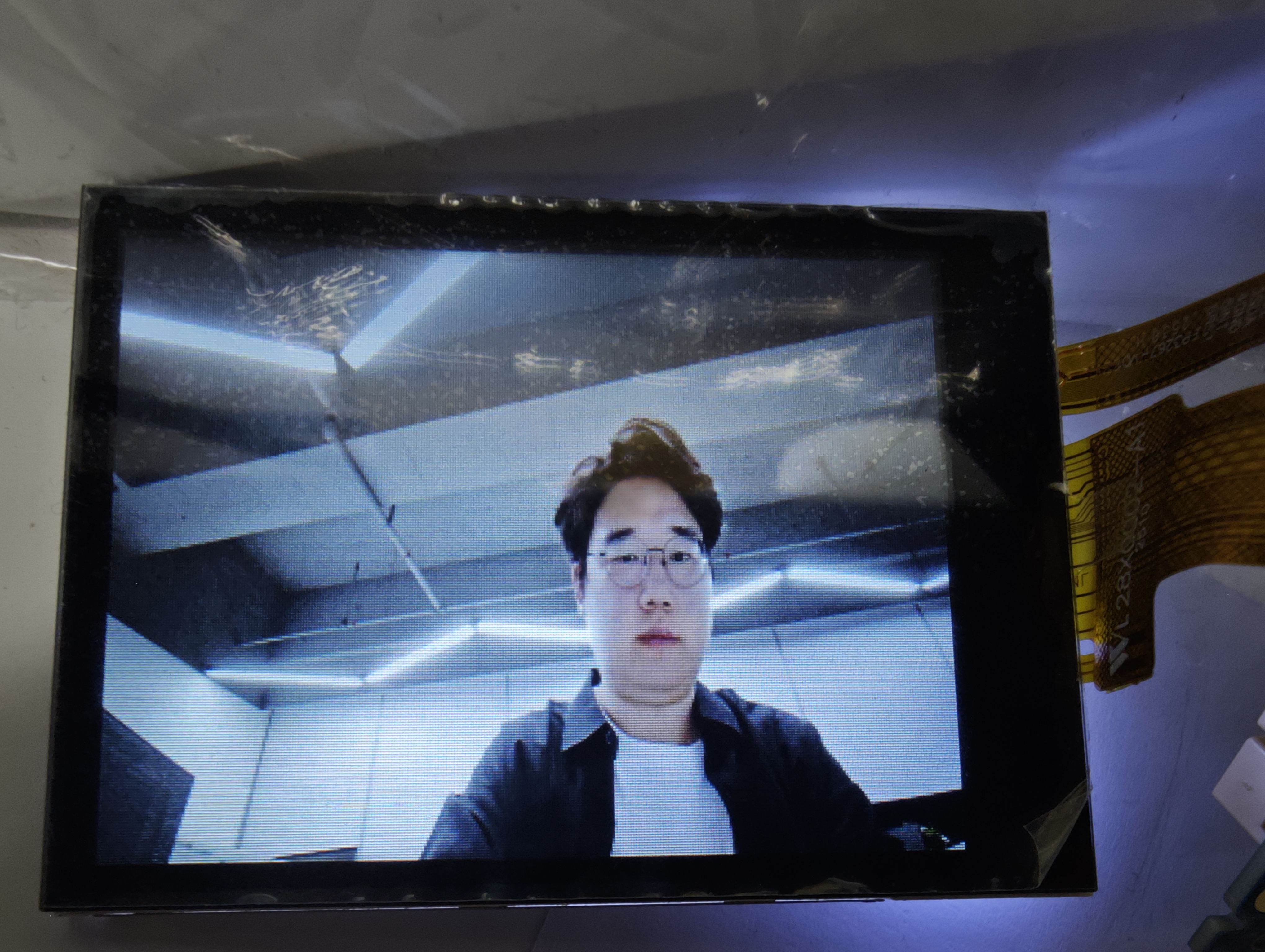
Effect Viewing
After normal streaming, the image collected by the sensor will be displayed on the SPI screen in real-time, with display specifications of 240x320 resolution and 20fps frame rate.
The program will print the following log:
Opening framebuffer device: /dev/fb0 Framebuffer device opened successfully (fd=3) Screen resolution: 240x320, 16 bpp Using double buffer mode: screenSize=153600, smem_len=307200, yres=320, yres_virtual=640 Framebuffer mapped successfully at address 0xXXXXXXXX SPI Panel initialized successfully SPI Panel display thread started, reading from SCL Dev0 Chn0 Port0 SPI Panel display started. Press Ctrl+C to exit... -
Exit Command
Press the
qkey to exit the demo. The program will clear the screen and exit normally
7. Additional Notes
Note that since the selected SPI Panel does not have a TE synchronization signal line, there may be tearing and jagged artifacts in motion scenes. For product deployment, it is recommended to select a screen with TE synchronization signal line.