PSPI Usage Reference
REVISION HISTORY
| Revision No. | Description |
Date |
|---|---|---|
| 1.0 | 04/02/2025 | |
| 1.1 | 11/24/2025 |
1. Overview
Serial Peripheral Interface (SPI) is a high-speed synchronous serial interface technology introduced by Motorola. It is primarily used in devices such as EEPROM, Flash memory, real-time clocks (RTCs), digital-to-analog converters (ADCs), and digital signal processors (DSPs).
This article mainly introduces the use of Sigmaster PSPI.
2. Keyword Description
-
D0: Master output, slave input (data from master)
-
D1: Master input, slave output (data from slave)
-
SCLK / SCK: Serial Clock signal, generated by the master and sent to the slave.
-
CS / SS: Slave Select signal, sent by the master to control which slave to communicate with; usually active low.
-
CPOL / CKP: Clock polarity, indicating the default high/low level of the clock.
-
CPHA / CKE: Clock phase, indicating the specific phase of the clock signal during data acquisition.
-
SPI Mode: Configuring the SPI clock polarity and phase allows for output of four SPI modes.
SPI Mode CPOL CPHA 0 [00] 0 0 1 [01] 0 1 2 [10] 1 0 3 [11] 1 1
3. Functional Description
-
PSPI (Programmable SPI) supports both master and slave modes.
-
PSPI does not support full-duplex, only half-duplex, and supports DMA mode. FIFO mode is only supported when using the master mode.
-
Both master and slave support 4-wire communication (MISO + MOSI + D0 + D1), 3-wire master communication (MOSI + SCLK + D0), and 3-wire slave communication (MOSI + SCLK + D1).
-
16-byte read/write buffer (FIFO mode), word transfer configurable bit width from 3 bits to 32 bits; DMA word width 8 bits.
-
Hardware preset chip select settings; PSPI supports two hardware chip selects.
-
Source Clock: 12MHz, 24MHz, pll_source/2MHz, pll_source/4MHz (pll_source defaults to 200MHz, adjustable to 192MHz). The Slave communication frequency is ¼ of the Source Clock. The selectable PSPI Master communication frequency is a division of each Source Clock, with a division factor of 1~255. Formula: speed = src_clk/(2*div + 2). The PSPI Slave's actual communication frequency will be selected at a level not less than the target frequency; the PSPI Master's actual communication frequency will be selected at a level closest to but less than the target frequency. Taking a Source Clock of 12MHz as an example, some divisions are shown in the table below. If the target frequency is 800000Hz, then the actual communication frequency is 750000Hz.
div SPI Clock Rate formula 1 3000000 Source Clock / 4 2 2000000 Source Clock / 6 3 1500000 Source Clock / 8 4 1200000 Source Clock / 10 5 1000000 Source Clock / 12 6 857142 Source Clock / 14 7 750000 Source Clock / 16 8 666666 Source Clock / 16 -
Number of PSPIs supported:
chipname bank pspi number iford 0x19 1
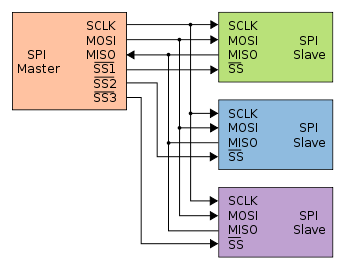
4. Hardware Connection
5. Kernel Usage Introduction
5.1. Kernel Config Configuration
The kernel uses PSPI, requiring the following configurations:
CONFIG_SPI=y //SPI core, required
CONFIG_SSTAR_PSPI=y //PSPI controller driver, required
CONFIG_SPI_SPIDEV=y //spidev device driver, optional
CONFIG_SPI_SLAVE=y //Enable slave mode
The menuconfig selections are as follows:
Device drivers->
    [*] SPI support->
        <*>   User mode SPI device driver support
        [*]   SPI slave protocol handlers

Device drivers->
    [*] SStar SoC platform drivers->
       <*> SStar PSPI driver
5.2. DTS Configuration
pspi: spi@1F003200 {
    compatible = "sstar,pspi";
    reg = <0x1F003200 0x200>;
    #address-cells = <1>;
    #size-cells = <0>;
    interrupts = <GIC_SPI INT_IRQ_PSPI02HOST IRQ_TYPE_LEVEL_HIGH>;
    clocks = <&CLK_pm_pspi0>;
#ifdef CONFIG_SPI_SLAVE
    pspi-slave;
#endif
    dma-enable;
    group = <1>;
    cs-num = <1>;
    status = "okay";
#ifdef CONFIG_SPI_SLAVE
    slave@0 {
        compatible = "ge,achc";
        reg = <0>;
    };
#else
    spidev1@0 {
        compatible = "ge,achc";
        reg = <0>;
    };
#endif
};
The following attributes can be configured in the PSPI driver:
| Attribute | Description | Remarks |
|---|---|---|
| compatible | Used for driver registration matching; must match the code | Modification prohibited |
| reg | Used to specify the address of the SPI register bank | Modification prohibited |
| interrupts | Used to specify the hardware interrupt number and attributes used | Modification prohibited |
| clocks | Used to specify the clock source used | Modification prohibited |
| pspi-slave | Used to specify whether to use slave mode | Can be modified as needed |
| group | Used to specify the SPI peripheral serial number | No modification required |
| dma-enable | Used to specify whether to enable DMA mode | Can be modified as needed |
| cs-num | Used to specify the number of CS pads included with the Engine | Can be modified as needed |
| status | Used to select whether to enable the SPI master driver | Can be modified as needed |
| slave@0 | Used to register SPI devices, exposing the node /dev/spidev*.* in user space. reg indicates which slice selector to choose. |
Only one slice selector can be selected. |
| spidev1@0 | Used to register SPI devices, exposing the node /dev/spidev*.* in user space. reg indicates which slice selector to choose. |
Can be added or removed as needed. |
5.2.1. pspi-slave
PSPI supports Master and Slave modes. To use it as a Slave, you need to configure the kernel as Slave and also configure the DTS as pspi-slave.
5.2.2. dma mode
The PSPI Master supports two basic communication modes: buffer mode and DMA mode. When the SPI Master is in buffer mode, software intervention is required for sending and receiving buffers, so the waveform is affected by software scheduling, resulting in intervals between each transmission.
When both the PSPI Master and Slave are in DMA mode, the driver only needs to set the addresses of the data to be sent and the addresses where the received data will be stored in the SPI Master's DMA-related registers. The SPI Master will then automatically and continuously send and receive data without software intervention. Therefore, when PSPI operates in DMA mode, the waveform continuity is better.
5.2.3. cs-num
The maximum value is the number of CS preset by the hardware. For example, if CS-num = 1, only one hardware CS will be used.
5.2.4. slave
In PSPI Slave mode, the macro CONFIG_SPI_SPIDEV must be configured when using the driver in drivers/spi/spidev.c to complete the registration of the spidev device. After registration, the /dev/spidev*.* character device will appear in user space. Only one device can be configured.
5.2.5. spidev
In PSPI Master mode, the macro CONFIG_SPI_SPIDEV must be configured when using the driver drivers/spi/spidev.c to complete the registration of the spidev device. After registration, the /dev/spidev*.* character device will appear in user space. The number of nodes can be added or removed based on the number of CS nodes.
5.3. PADMUX Configuration
Configuring PSPI in a Linux environment using padmux only requires adding the corresponding padmux.dtsi line according to the selected pin. For example, the PSPI0 mode1 pin is configured as follows:
<PAD_PM_PSPI0_DI       PINMUX_FOR_PM_PSPI0_MODE_1      MDRV_PUSE_PSPI0_MISO0>,
<PAD_PM_PSPI0_DO       PINMUX_FOR_PM_PSPI0_MODE_1      MDRV_PUSE_PSPI0_MOSI0>,
<PAD_PM_PSPI0_CK       PINMUX_FOR_PM_PSPI0_MODE_1      MDRV_PUSE_PSPI0_CLK>,
<PAD_PM_PSPI0_CZ       PINMUX_FOR_PM_PSPI0_MODE_1      MDRV_PUSE_PSPI0_CS>,
The first column is the pin index number, which can be found in drivers/sstar/include/{chipname}/gpio.h;
The second column is the mode definition, located in the m_hal_gpio_st_padmux_entry array in drivers/sstar/gpio/{chipname}/hal_pinmux.c. This array lists the multiplexing relationships of all pins; you can query this array to see which multiplexing functions a pin supports;
The third column is the pin and its pairing mode index name, which can be found in drivers/sstar/include/drv_puse.h. Please configure it to the PSPI-related puse.
6. Test Case Description
6.1 Linux Reference Use Cases
-
drivers/sstar/pspi/ut/pspi_ut.c
Example: As the master, test the read/write of the external NAND flash memory.
./pspi_ut -D /dev/spidev1.0 -s 6000000
7. PSPI Limitations
- When reading more than 512 bytes of data from an external source in PSPI DMA mode, the maximum operating frequency of PSPI must be less than or equal to ½ PM IMI (DMA buffer at PM IMI).
8. FAQ
-
A PSPI slave can only connect to an SPI master.
-
The voltage of the four pins of the slave and master must be the same, such as 1V8, and they must share a common ground.
-
If the captured data is somewhat abnormal, increase the pin drive capability.
-
The data size transmitted and received by the master and slave must be the same. Otherwise, the slave driver may get stuck.
-
Note that the slave's clock speed should not be greater than the master's clock speed.
-
The PSPI DMA mode buffer driver is configured to 4KB. If you need to increase/decrease it, modify the value of
PSPI_DMA_ALLOC_SIZEin kernel/driver/sstar/pspi/drv_pspi.c.If using spidev.c, you also need to modify the value ofbufsizin/kenrel/drivers/spi/spidev.c. In spidev.c, the default value ofbufsizis 4096, which is 4kB. -
Since the SPI communication clock is generated by the Master, you should wait for the Slave to be ready before executing the Master's Clock output operation.
-
Verify the pin connections and padmux configuration are correct. Pay attention to the PUSE configuration of the Clock pin. If PUSE is configured incorrectly, it may cause abnormal waveforms when CPOL=1, resulting in communication failure.