AiGlasses Function Introduction
1. Overview
This document is a supplement to the AI Glasses Program Description, providing a more detailed introduction to AI Glasses functions.
1.1 Specifications
- Sensor: IMX681
- ISP: multichannel, HDR off
- LDC: distortion correction, EIS
- SCL: image scaling
- VENC:
- Photography: 12M(4032x3024) 1fps, requires jpg encoding
- Video recording: 3M(2016x1512) 30fps H265
2. Scenario Introduction
The following diagram shows the complete structure of this demo, where white parts indicate unimplemented features.

2.1 System Component Introduction
2.1.1 Core Hardware Components
- ISP Main Controller: Main chip SSC309QL, running the main control program, responsible for core functions such as image processing, photography, and video recording
- TWS: High-specification Bluetooth audio chip WQ7036AX, supports audio processing and voice wake-up, interacts with the main chip and Wi-Fi
- Wi-Fi Module: Responsible for wireless transmission of photo and video files
- CMOS Sensor and Inertial Sensor Combination:
- CMOS Sensor: Image acquisition
- G Sensor: Inertial sensor ICM42607, supports gravity sensing and motion detection
- ALS (Ambient Light Sensor): Ambient light detection
2.1.2 Interactive Peripherals
- Photo/Video Recording Button:
- Short press (<500ms): Triggers photo function
- Long press (500ms-2s): Triggers video recording function
- Open/Close Detection: Glasses open/close status detection function (not implemented in this demo)
- Touch Strip: Touch interaction area (not implemented in this demo)
- Status Indicator: Shows different colored indicator lights according to different functional scenarios, providing status feedback (not implemented in this demo)
2.1.3 Audio System
- Digital Microphone (DMIC): Supports 2 Channel 2 DMIC configuration, providing high-quality audio acquisition
- Speaker System:
- Default uses single-stage op-amp IC
- TWS transmits audio data to the speaker through IIS interface for playback
2.1.4 Environmental Perception
- Photosensitive Sensor: Real-time detection of ambient light changes, converts optical signals to electrical signals, supports the image sensor to automatically adjust parameters according to lighting conditions
The SOC end connects to Wi-Fi module, eMMC, sensor and gyroscope, TWS connects to charging IC, digital photosensitive, audio peripherals and related user interaction peripherals. SOC sends command requests to TWS through Uart and receives control instructions from TWS, receives audio data from TWS through I2S interface, and sends thumbnails to TWS through PSPI. SOC transmits image data to the mobile phone end through Wi-Fi.
2.2 Module Power Status in Various Scenarios
In the scenario diagram, gray parts indicate modules in power-off state.
-
Idle State

-
Photo/Video Recording

-
Wi-Fi Transfer Photos/Video Files

-
Standby
SOC enters STR mode, DDR remains powered.

3. Function Introduction
3.1 Photography

-
In photography scenario, sensor uses 4032x3024 resolution, frame rate is 15fps. 3DNR is performed when passing through ISP. Because the maximum size of ISP single frame processing is 3840x3840, multichn settings need to be enabled, dividing an image into two parts for separate processing in two channels, and then spliced into one.
-
AESTABLE module gets buffer from ISP module and checks AE status. When judging AE as stable state, it passes the stable buffer to LDC. Because photography only processes one buffer, based on power consumption considerations, VIF and ISP modules are unbound in advance, VIF/ISP output ports are disabled, and then sensor is stopped.
-
LDC module performs distortion correction on input images, outputs one photography image and one 720p thumbnail, needs to access SCL module for scaling down.
-
SCL's input port has width limitation for NV12 format images, maximum cannot exceed 3840, but has no limitation for YUYV format, so LDC inputs YUYV format data. SCL internally performs image format conversion to output NV12 data. SCL outputs images to VENC for encoding.
-
Two VENC encodings save jpeg files for photography and thumbnails respectively. After file saving is completed, VENC, SCL, LDC output ports will be disabled sequentially from back to front.
3.2 Video Recording

-
In video recording scenario, sensor uses 2016x1512 resolution, frame rate is 30fps. 3DNR is performed when passing through ISP.
-
AESTABLE module gets buffer from ISP module and checks AE status. When judging AE as stable state, it passes the stable buffer to LDC. Video recording continuously processes data until receiving stop recording instruction.
-
LDC module performs distortion correction and anti-shake on input images, outputs one H265 stream and one 720p thumbnail.
-
Two VENC encodings save all image data as H265 video file and take first frame image data to save jpeg file respectively. When receiving stop recording instruction, file saving is completed, VENC, LDC will be disabled sequentially from back to front, then VIF and ISP modules are unbound, and ISP, VIF output ports are disabled, finally sensor is stopped.
3.3 File Transfer

-
PSPI Transfer Thumbnails (not implemented in this demo)
Thumbnails generated from photography and video recording will be transmitted to TWS through PSPI protocol. TWS end Bluetooth is always on. When the host computer browses, thumbnails will be transmitted from TWS to the host computer through Bluetooth protocol.
-
Wi-Fi Module Control
The Wi-Fi module connects to the SoC end through SDIO interface, and its power pin is controlled by TWS for power on/off.
-
Host Computer Bluetooth Commands (not implemented in this demo)
The host computer sends instructions to download photo/video files to TWS through Bluetooth (demo board simulates Bluetooth instructions with button trigger method). After TWS end receives instructions from the host computer, it will add file download tasks to the task pending list, and power on Wi-Fi. Wi-Fi defaults to AP mode after power on.
-
Host Computer Connection Detection
The Wi-Fi module has another pin connected to TWS for detecting host computer connection. This pin is pulled high by default. When Wi-Fi detects that the host computer connects to the hotspot, it will pull this pin low to notify TWS.
-
FTP Server Startup
After receiving the connection event, TWS will check the SoC status and automatically power on the SoC, then send
E_AIGLASSES_DATA_TYPE_TASK_TRANSevent to the SoC. Upon receiving the event, the SoC will load the Wi-Fi driver, obtain IP, and create an FTP server. After that, the host computer can access the FTP server to read image/video files from the SoC. -
Transfer End
When TWS end receives the end file download instruction sent by the host computer, TWS will actively send a message to end file download to SoC end. After receiving it, SoC will first close ftp server, then reply
E_AIGLASSES_DATA_TYPE_TASK_DONEto TWS. After TWS end receives it, it will control Wi-Fi power off, and if the task list is empty, it will also power off the SoC.
Note
The demo does not implement thumbnail transmission to TWS through PSPI protocol or host computer sending transfer instructions to TWS via Bluetooth. You need to refer to the above process to implement it yourself.
3.4 AESTABLE Module Introduction
3.4.1 Module Processing Flow
AESTABLE module is a user layer module, connected to the backend of ISP module. It controls whether image data is directly transmitted to the next level module or waits until image effect is stable before starting transmission to the next level module by checking whether the image effect processed by ISP module reaches stable state, and controls the number of transmitted image data.
AESTABLE processing flow is as follows:

APP receives digital photosensitive lux value, queries shutter and gain values according to ae table, then sets them to ISP to achieve acceleration convergence effect. After APP sets shutter and gain values, it will query ISP's AE status. If AE reaches stable state, AESTABLE module gets buffer from ISP's output port and injects it into the next level's input port.
3.4.2 Module Attribute Description
-
SGS_GLASSES_AESTABLE_ControlTypeE_t
- E_SGS_GLASSES_AESTABLE_CONTROL_AUTO: Automatic mode, ISP judges whether the received image's AE reaches stable state, unstable image frames are all discarded.
- E_SGS_GLASSES_AESTABLE_CONTROL_FORCE: Force mode, does not judge AE's stable state, discards specified number of image frames, takes the received image after that.
3.5 Image Stabilization Function
The camera on smart glasses typically shakes with the wearer's head movements. This physical motion-induced shake degrades video visual quality and may affect subsequent image recognition or feature extraction tasks. Enhancing image stability through stabilization technology is a fundamental requirement for ensuring user experience of wearable imaging devices.
3.5.1 Common Stabilization Technology Classification
In the field of imaging processing, common stabilization solutions are mainly divided into the following categories:
-
Digital Image Stabilization (DIS): A software algorithm-based stabilization technology, whose core typically adopts Global Motion Estimation (GME). This technology analyzes pixel offsets between adjacent frames to extract motion vectors.
- Advantages: No additional hardware sensors required.
- Limitations: Difficult to distinguish between camera motion and autonomous motion of objects in the scene (prone to "background dragging" phenomenon); stabilization performance degrades in low light or when scene features are blurry.
-
Electronic Image Stabilization (EIS): A technology combining hardware sensing with software algorithms. It uses the Inertial Measurement Unit (IMU) (containing gyroscope and accelerometer) to obtain the device's physical orientation, and accordingly crops and reconstructs image frames.
- Advantages: Compensation calculation does not depend on image content, maintaining good stability in complex environments or large-amplitude motions.
-
Optical Image Stabilization (OIS): Uses physical displacement of the lens module or sensor component to offset mechanical shaking.
- Advantages: Direct compensation at the imaging stage, no pixel-level cropping involved, minimal image quality loss.
- Limitations: Hardware module is larger in size and higher in cost.
This program adopts EIS by default, utilizing the built-in six-axis gyroscope ICM42607 to obtain real-time orientation data, and collaborating with the SoC's internal Lens Distortion Correction (LDC) hardware unit to perform image transformation. Through the collaboration of hardware accelerators, the system can achieve real-time stable processing of high-frame-rate video while maintaining low CPU load.
3.5.2 Electronic Stabilization Function Configuration
The core of Electronic Image Stabilization (EIS) lies in converting the sensor's physical motion into reverse compensation on the image plane. The specific process is as follows:
3.5.2.1 Create LDC Channel
MI_LDC_WORKMODE_DIS_LDC represents DIS mode superimposed with LDC mode, performing distortion correction on the image first, then performing stabilization processing.
MI_LDC_ChnAttr_t stLdcChnAttr = {0};
stLdcChnAttr.eInputBindType = E_MI_SYS_BIND_TYPE_FRAME_BASE;
stLdcChnAttr.eWorkMode = MI_LDC_WORKMODE_DIS_LDC;
MI_LDC_CreateChannel(u32DevId, u32ChnId, &stLdcChnAttr);
3.5.2.2 Configure LDC Region Mode and Distortion Correction File
MI_LDC_REGION_NORMAL: Normal correction modeCalibPoly_new_bin_memAddress: Memory address of distortion correction bin fileMI_LDC_ChnLDCAttr_t stLdcModeChnAttr = {0}; stLdcModeChnAttr.stRegionAttr[0].eRegionMode = MI_LDC_REGION_NORMAL; stLdcModeChnAttr.stCalibInfo.pCalibPolyBinAddr = CalibPoly_new_bin_memAddress; MI_LDC_SetChnLDCAttr(u32DevId, u32ChnId, &stLdcModeChnAttr);
3.5.2.3 IMU and Sensor Rotation Matrix
The as32RotationMatrix matrix parameters need to be configured according to the spatial relative position of the gyroscope and sensor. Please refer to IS User Manual.
MI_LDC_ChnDISAttr_t stEisModeChnAttr = {0};
int value[9] = {1, 0, 0, 0, 1, 0, 0, 0, 1};
memcpy(&stEisModeChnAttr.as32RotationMatrix, &value, sizeof(value));
MI_LDC_SetChnDISAttr(pstSrcChnPort->u32DevId, pstSrcChnPort->u32ChnId, &stEisModeChnAttr);
Taking Comake PI D2 platform as an example, the gyroscope and sensor coordinate systems are as follows:
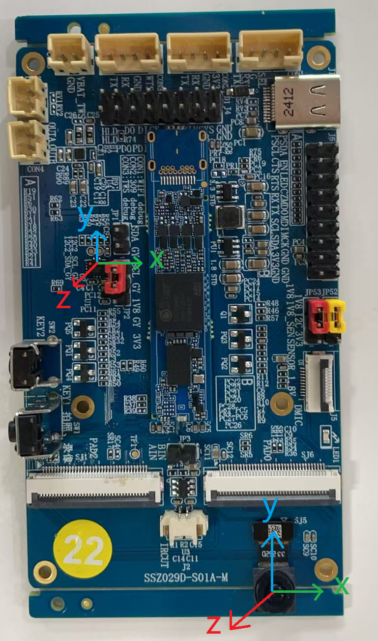
This corresponds to the scenario in the following figure of the IS User Manual, therefore the corresponding rotation matrix is {1, 0, 0, 0, 1, 0, 0, 0, 1}.

3.5.2.4 Zero Drift Calibration
MI_LDC_CalibIMUBaseDrift provides zero drift calibration functionality. After enabling the algorithm zero drift correction function, no manual intervention is required during the entire process, and correction data can be obtained after correction is completed. The correction data can be saved for subsequent use when starting the EIS function.
3.5.2.5 Input and Output Parameters
The width and height information of the input image directly inherits the output image information of the previous module. The output image parameters after enabling the EIS function will be different from the input parameters because electronic stabilization will crop the image to ensure the stability of the central image. Note that the width and height of the output image must be 32-byte aligned.
MI_LDC_SetOutputPortAttr(u32DevId, u32ChnId, &stOutputPortAttr);
3.5.2.6 EIS Function Start and End
Since the EIS function depends on the spatial axis data information of the external gyroscope, when EIS is enabled, it is necessary to ensure that the external gyroscope has been powered on until the EIS function is disabled. This demo only powers the gyroscope when starting the recording task, so MI_LDC_StartChannel will not be called during pipeline initialization. Only the corresponding start and end interfaces are called before and after recording, and after calling MI_LDC_StopChannel, the external gyroscope will be powered off to ensure low power consumption during standby.
4. Environment Configuration and Running
4.1 Dependent Resource Files
-
demo bin file
-
prog_ai_glasses_sample
Demo executable file, by default packaged to board /customer/sample_code/bin directory. If manually compiling demo, please copy generated prog_ai_glasses_sample to board /customer/sample_code/bin directory.
-
IQ bin
After compiling and flashing with the defconfig given above, IQ bin will be packaged to the board by default.
-
imx681_12m_comake_1201.bin
Photography scenario sensor api bin, located in board /config/iqfile directory.
-
imx681_3m_comake_1201.bin
Video recording scenario sensor api bin, located in board /config/iqfile directory.
-
12m_alsc_cali.data
Photography scenario lens compensation correction, located in board /config/iqfile directory.
-
12m_ne_cali.data
Photography scenario 3DNR Noise type analysis correction, located in board /config/iqfile directory.
-
3m_ne_cali.data
Video recording scenario 3DNR Noise type analysis correction, located in board /config/iqfile directory.
-
CalibPoly_new.bin
LDC distortion correction, located in board /customer/sample_code/bin/resource directory.
-
setup_rndis.sh
Virtual network card configuration script, requires PC to install USB RNDIS driver first, for debugging use. Located in board /customer/sample_code/bin/resource directory.
4.2 Running Demo
# If you modified the path of prog_ai_glasses_sample, ensure that the resource directory and prog_ai_glasses_sample are in the same directory.
cd /customer/sample_code/bin
./prog_ai_glasses_sample
4.2.1 Running Parameter List
prog_ai_glasses_sample keeps running after default startup until receiving SIGINT or SIGTERM signals to exit.
-
nostr: When task queue is empty, do not enter suspend, instead sleep 10s. By default, when task queue is empty, enter suspend.
-
nosig: Do not capture SIGINT, SIGKILL, SIGTERM signals. By default, captures the above signals.
-
nopipe: Do not initialize pipeline, only debug other functions except photography and video recording.
4.2.2 Application Processing Flow
Note
The development board defaults to long-powered idle mode when booting. Need to run prog_ai_glasses_sample from command line, notify TWS to enter AI glass mode, then can enter the following process.
TWS end triggers events through buttons, adds corresponding tasks to TWS end task list. If SOC is in power-off state, it will power on SOC. After device power on, it automatically runs prog_ai_glasses_sample, initializes pipeline, after initialization is completed, SOC enters suspend. When events trigger wake-up, demo will request to process TWS end's tasks, and process according to task types. After task processing is completed, demo will continue to request new tasks. If no tasks are requested, SOC will enter suspend state (power off).

4.2.2.1 Photography Processing Flow
When photography event is triggered, enter photography processing flow. App will pass photosensitive lux value and photo count parameters, query corresponding shutter/gain values according to lux to set sensor ae parameters, then start sensor to start photography. In continuous photography scenario, only need to set ae parameters and start sensor before the first frame. When photography task is completed, sensor will be stopped.

4.2.2.2 Video Recording Processing Flow
When start video recording event is triggered, enter video recording processing flow. App will pass photosensitive lux value, query corresponding shutter/gain values according to lux to set sensor ae parameters, then start sensor to start video recording. When end video recording event is triggered, will exit video recording processing flow, end video recording then stop sensor.

4.2.2.3 Wi-Fi Transfer Processing Flow
When start Wi-Fi transfer event is triggered, enter file transfer processing flow. Wi-Fi powers on and initializes to AP mode. When Wi-Fi receives host computer's connection request, SOC powers on, then SOC end loads Wi-Fi driver, gets IP and establishes ftp server, starts receiving file transfer requests. When end Wi-Fi transfer event is triggered, will exit file transfer processing flow, close ftp server then send file transfer task completed message to TWS end. TWS receives message then powers off Wi-Fi.

5. Development Guide
5.1 Interactive Protocol
5.1.1 UART Protocol
5.1.1.1 Message Structure
    +-----------------------------+
    |            Header           |     Message header, 4 bytes, fixed 0x5A5A5A5A
    +-----------------------------+
    |            CmdType          |     Message processing type, 1 byte, 0: REQ; 1: ACK
    +-----------------------------+
    |            CmdId            |     Message ID, 1 byte, detailed description in section 5.1.1.2
    +-----------------------------+
    |        Accept in ACK        |     ACK processing status, 1 byte, 0: accept request; 1: reject request. All handled as 0, no business need to reject requests currently.
    +-----------------------------+
    |           SOC state         |     SOC state, 1 byte, detailed description in section 5.1.1.3
    +-----------------------------+
    |          user define        |     User defined, 2 bytes, bit[0~7]: task sequence number; bit[8~15]: task parameters
    +-----------------------------+
    |             Tail            |     Message tail, 4 bytes, fixed 0xA5A5A5A5
    +-----------------------------+
5.1.1.2 Message Types
| Message ID | Description | Usage Scenario |
|---|---|---|
| E_AIGLASSES_DATA_TYPE_TASK_NONE | Task queue is empty | MCU to SOC |
| E_AIGLASSES_DATA_TYPE_TASK_PHOTO | Photography | MCU to SOC |
| E_AIGLASSES_DATA_TYPE_TASK_START_REC | Start video recording | MCU to SOC |
| E_AIGLASSES_DATA_TYPE_TASK_STOP_REC | Stop video recording | MCU to SOC |
| E_AIGLASSES_DATA_TYPE_TASK_TRANS | Start downloading files from ftp server through Wi-Fi | MCU to SOC |
| E_AIGLASSES_DATA_TYPE_TASK_STOP_TRANS | Stop downloading files from ftp server | MCU to SOC |
| E_AIGLASSES_DATA_TYPE_TASK_POWEROFF_WIFI | Turn off Wi-Fi after transfer ends | MCU to SOC |
| E_AIGLASSES_DATA_TYPE_TASK_POWEROFF_OK | SOC responds to power-off request | SOC to MCU |
| E_AIGLASSES_DATA_TYPE_TASK_REQUEST | SOC requests to process the first task in MCU's task queue | SOC to MCU |
| E_AIGLASSES_DATA_TYPE_TASK_DONE | SOC notifies MCU that the current requested task has been completed | SOC to MCU |
| E_AIGLASSES_DATA_TYPE_TASK_HEARTBEAT | SOC sends heartbeat packet to MCU | SOC to MCU |
| E_AIGLASSES_DATA_TYPE_TASK_INDEF_LEN_MSG | User-defined variable-length message | SOC to MCU & MCU to SOC |
5.1.1.3 SOC States
| SOC State | Description |
|---|---|
| E_AIGLASSES_DATA_TYPE_STATE_RESUMING | SOC is in wake-up process. Not used currently |
| E_AIGLASSES_DATA_TYPE_STATE_IDEL | SOC is in idle state |
| E_AIGLASSES_DATA_TYPE_STATE_CAP_PIC | SOC is taking photos |
| E_AIGLASSES_DATA_TYPE_STATE_REC | SOC is recording video |
| E_AIGLASSES_DATA_TYPE_STATE_TRANS | SOC is uploading files |
| E_AIGLASSES_DATA_TYPE_STATE_SUSPENDING | SOC starts entering suspend state |
| E_AIGLASSES_DATA_TYPE_STATE_SUSPENDED | SOC's suspend process is completed, ready to power off |
5.1.1.4 Serial Communication Description
-
MCU and SOC both have their own work queues, which store pending tasks. Task types are consistent with message IDs.
-
During MCU and SOC operation, SOC will periodically send heartbeat packets to MCU. When SOC sends messages to MCU, it carries SOC status information.
-
On MCU end, when photography, video recording, file transfer events are triggered, corresponding tasks will be added to MCU's work queue. If SOC is not powered on, triggering these events will power on SOC.
-
On SOC end, after running demo on startup or when device wakes up from standby after running demo, or when SOC completes the previous task, SOC will check whether its work queue is empty.
-
If empty, SOC state is set to E_AIGLASSES_DATA_TYPE_STATE_IDEL, and sends E_AIGLASSES_DATA_TYPE_TASK_REQUEST command to MCU. After MCU receives E_AIGLASSES_DATA_TYPE_TASK_REQUEST, it will check its work queue. If work queue is not empty, return the first task in the queue to SOC for processing; if work queue is empty, return E_AIGLASSES_DATA_TYPE_TASK_NONE message to SOC. After SOC receives E_AIGLASSES_DATA_TYPE_TASK_NONE message, it will send an E_AIGLASSES_DATA_TYPE_TASK_HEARTBEAT message with E_AIGLASSES_DATA_TYPE_STATE_SUSPENDING status information to MCU, then SOC starts executing suspend operation.
-
If not empty, SOC takes task from work queue for processing. According to different task types, SOC's behaviors are as follows:
-
If task type is E_AIGLASSES_DATA_TYPE_TASK_PHOTO, E_AIGLASSES_DATA_TYPE_TASK_START_REC or E_AIGLASSES_DATA_TYPE_TASK_TRANS, SOC's state changes to E_AIGLASSES_DATA_TYPE_STATE_CAP_PIC, E_AIGLASSES_DATA_TYPE_STATE_REC or E_AIGLASSES_DATA_TYPE_STATE_TRANS respectively. At this time, if heartbeat packet is sent, the SOC status carried by heartbeat packet is the changed state. When task processing is completed, SOC state changes to E_AIGLASSES_DATA_TYPE_STATE_IDEL, and returns E_AIGLASSES_DATA_TYPE_TASK_DONE message to MCU.
-
If task type is E_AIGLASSES_DATA_TYPE_TASK_STOP_REC or E_AIGLASSES_DATA_TYPE_TASK_STOP_TRANS, SOC ends the currently processing video recording task or file transfer task, then SOC's state changes to E_AIGLASSES_DATA_TYPE_STATE_IDEL, and returns E_AIGLASSES_DATA_TYPE_TASK_DONE message to MCU.
-
-
After SOC executes suspend operation, in the kernel suspend end phase, it will write serial port register to send E_AIGLASSES_DATA_TYPE_TASK_POWEROFF_OK message to MCU. The message carries SOC status as E_AIGLASSES_DATA_TYPE_STATE_SUSPENDED. After MCU receives it, it will execute power-off operation on SOC.
5.1.1.5 Photography Video Recording Serial Interaction Flow Example

5.1.2 PSPI Protocol
PSPI protocol is mainly used for transmitting thumbnail data. This demo program has not implemented this function yet. For understanding SPI usage methods, please refer to independent demo code sdk/verify/sample_code/source/iford/spi/Readme.md. For detailed description of SPI protocol, please refer to SPI Usage Reference.
5.1.3 IIS Protocol
IIS protocol is used for transmitting audio data between SOC and TWS.
5.1.3.1 Data Flow
Audio data is transmitted between SOC and TWS through IIS interface, where SOC acts as IIS RX, TWS acts as IIS TX. Overall data flow is as follows:

TWS needs to get dmic audio data through PDM interface, then send it to SOC through IIS TX. Currently TWS has a dmic recording demo, which can continuously record and send out through IIS after flashing and powering on.
SOC needs to receive TWS's data through IIS RX. Currently there is a demo on SOC end sdk/verify/sample_code/source/iford/audio/ai_demo for dumping audio data from TWS into WAV files. This demo depends on Sigmastar's MI audio module.
5.1.3.2 IIS Configuration
For SOC and TWS to use IIS to transmit audio data, some key IIS configurations need to be consistent between both parties.
5.1.3.2.1 Specify Getting Audio Data from IIS RX
For MI audio in module, there can be multiple data input interfaces, such as AMIC, DMIC, IIS RX, etc.
MI_AI_If_e           enAiIIS    = E_MI_AI_IF_I2S_A_01;
ST_Common_AiAttachIf(stAiDevId, stChnGrpId, &enAiIIS, 1);
5.1.3.2.2 IIS Quantization Bits
Represents transmitted audio data
Note: SOC's IIS RX can only use 16-bits, so TWS end also can only use 16-bits
MI_AUDIO_I2sConfig_t stI2SConfig;
stI2SConfig.enBitWidth   = E_MI_AUDIO_BIT_WIDTH_16;
MI_AI_SetI2SConfig(E_MI_AI_IF_I2S_A_01, &stI2SConfig);
5.1.3.2.3 IIS Data Format
IIS has three data formats: standard IIS mode (Philips standard), left justified mode, right justified mode.
MI_AUDIO_I2sConfig_t stI2SConfig;
stI2SConfig.enFormat     = E_MI_AUDIO_I2S_FMT_LEFT_JUSTIFY_MSB;
MI_AI_SetI2SConfig(E_MI_AI_IF_I2S_A_01, &stI2SConfig);
5.1.3.2.4 IIS Slave Mode Specification
SOC acts as IIS RX, so needs to be set to IIS slave mode, specified by E_MI_AUDIO_I2S_MODE_I2S_SLAVE.
MI_AUDIO_I2sConfig_t stI2SConfig;
stI2SConfig.enMode       = E_MI_AUDIO_I2S_MODE_I2S_SLAVE;
MI_AI_SetI2SConfig(E_MI_AI_IF_I2S_A_01, &stI2SConfig);
5.1.3.2.5 IIS Sample Rate
IIS sample rate also needs to be consistent with peer TWS
MI_AUDIO_I2sConfig_t stI2SConfig;
stI2SConfig.enSampleRate = E_MI_AUDIO_SAMPLE_RATE_8000;
MI_AI_SetI2SConfig(E_MI_AI_IF_I2S_A_01, &stI2SConfig);
5.1.3.3 IIS Recording Demo Running
SOC end implements recording demo through IIS rx can refer to: sdk/verify/sample_code/source/iford/audio/ai_demo, corresponding usage documentation is in same directory Readme.md.
-
Flash TWS firmware and start TWS, firmware will continuously record from DMIC and send to SOC end through IIS TX.
-
Compile SOC end demo
cd sdk/verify/sample_code/
make source/iford/audio/ai_demo
After compilation, prog_audio_ai_demo will be generated in sample_code/out/arm/app directory.
-
Execute SOC end demo, and speak to DMIC
./prog_audio_ai_demo iis -
Execution result
Will record 10s from IIS RX to get audio data, and dump to WAV file.
5.2 API Description
| API Name | Function |
|---|---|
| SGS_GLASSES_PIPE_MediaInit | Initialize pipeline |
| SGS_GLASSES_PIPE_MediaCapture | Photography command |
| SGS_GLASSES_PIPE_MediaStartRecord | Start video recording |
| SGS_GLASSES_PIPE_MediaStopRecord | End video recording |
| SGS_GLASSES_MESSENGER_Init | Serial port initialization, create data receiving thread |
| SGS_GLASSES_MESSENGER_DeInit | Wait for data receiving thread to end, close serial port |
| SGS_GLASSES_MAIN_SignalThreadCanExit | End data receiving thread |
| SGS_GLASSES_MESSENGER_RegisterNotifyReceiver | Parse serial port received data |
| SGS_GLASSES_MESSENGER_Send | Build serial port sending data |
| SGS_GLASSES_EIS_ImuCalib | Gyroscope zero drift calibration |
5.2.1 SGS_GLASSES_PIPE_MediaInit
-
Function
Initialize pipeline
-
Syntax
MI_S32 SGS_GLASSES_PIPE_MediaInit(); -
Parameters
None
-
Return Value
MI_SUCCESS: Success
Non MI_SUCCESS: Failure
5.2.2 SGS_GLASSES_PIPE_MediaCapture
-
Function
Photography command
-
Syntax
MI_S32 SGS_GLASSES_PIPE_MediaCapture(const char *pSaveFileName, const char *pSaveThumbnail, MI_U32 currIdx, MI_U32 totalNum, MI_S32 externLux, SGS_GLASSES_PIPE_MediaType_t mediaType); -
Parameters
Parameter Name Description Input/Output pSaveFileName Path to save photography image Input pSaveThumbnail Path to save photography thumbnail Input currIdx Not used Input totalNum Expected number of photos Input externLux TWS end photosensitive lux value Input mediaType Media type Input -
Return Value
MI_SUCCESS: Success
Non MI_SUCCESS: Failure
5.2.3 SGS_GLASSES_PIPE_MediaStartRecord
-
Function
Start video recording
-
Syntax
int SGS_GLASSES_PIPE_MediaStartRecord(const char *pSaveFileName, const char *pSaveThumbnail, MI_S32 externLux); -
Parameters
Parameter Name Description Input/Output pSaveFileName Path to save video recording file Input pSaveThumbnail Path to save video recording thumbnail Input externLux TWS end photosensitive lux value Input -
Return Value
MI_SUCCESS: Success
Non MI_SUCCESS: Failure
5.2.4 SGS_GLASSES_PIPE_MediaStopRecord
-
Function
End video recording
-
Syntax
MI_S32 SGS_GLASSES_PIPE_MediaStopRecord(); -
Parameters
None
-
Return Value
MI_SUCCESS: Success
Non MI_SUCCESS: Failure
5.2.5 SGS_GLASSES_MESSENGER_Init
-
Function
Serial port initialization, create data receiving thread
-
Syntax
MI_S32 SGS_GLASSES_MESSENGER_Init(void* protcolTaskHandler, MI_BOOL bEnableDma); -
Parameters
Parameter Name Description Input/Output protcolTaskHandler Command parsing factory function pointer Input bEnableDma Whether to enable DMA Input -
Return Value
0: Success
Non 0: Failure
5.2.6 SGS_GLASSES_MESSENGER_DeInit
-
Function
Wait for data receiving thread to end, close serial port
-
Syntax
MI_S32 SGS_GLASSES_MESSENGER_DeInit(void); -
Parameters
None
-
Return Value
0: Success
Non 0: Failure
5.2.7 SGS_GLASSES_MAIN_SignalThreadCanExit
-
Function
End data receiving thread
-
Syntax
MI_BOOL SGS_GLASSES_MAIN_SignalThreadCanExit(void); -
Parameters
None
-
Return Value
TRUE: Success
FALSE: Failure
5.2.8 SGS_GLASSES_MESSENGER_RegisterNotifyReceiver
-
Function
Parse received data
-
Syntax
MI_S32 SGS_GLASSES_MESSENGER_RegisterNotifyReceiver(MI_S32 (*pstNotifyFun)(AIGLASSES_DATA_TYPE_ProtrcolTask_t* taskInfo)); -
Parameters
Parameter Name Description Input/Output pstNotifyFun Task receiving function pointer Input -
Return Value
0: Success
Non 0: Failure
5.2.9 SGS_GLASSES_MESSENGER_Send
-
Function
Send data
-
Syntax
MI_S32 SGS_GLASSES_MESSENGER_Send(AIGLASSES_DATA_TYPE_ProtrcolTask_t* sendInfo, unsigned char needCheck); -
Parameters
Parameter Name Description Input/Output sendInfo Send data Input needCheck Whether data verification is needed Input -
Return Value
MI_SUCCESS: Success
Non MI_SUCCESS: Failure
5.2.10 SGS_GLASSES_EIS_ImuCalib
-
Function
Gyroscope zero drift calibration
-
Syntax
MI_S32 SGS_GLASSES_EIS_ImuCalib(MI_S32 ldcdevId, MI_S32 ldcChnId); -
Parameters
Parameter Name Description Input/Output ldcdevId LDC device number Input ldcChnId LDC channel number Input -
Return Value
MI_SUCCESS: Success
Non MI_SUCCESS: Failure