SigmaStar eMMC User Guide
REVISION HISTORY
| Revision No. | Description |
Date |
|---|---|---|
| 1.0 | 06/27/2023 | |
| 2.0 | 12/13/2023 |
1. INTRODUCTION
The MMC under Kernel adopts the standard Linux framework, which allows it to use the standard interface to drive various MMC Devices (such as eMMC card, SD card, or SDIO device).
The MMC subsystem consists of card layer, core layer, and host layer. The Card layer registers the entire MMC Device as an MMC Block Device, which can support the data request of the upper layer; the Core layer implements the initialization process, as well as reading and writing, according to the MMC/SD/SDIO protocol. The host layer mobilizes the hardware and communicates the cmd or data request from the core layer with eMMC/SD/SDIO card through FCIE/SDIO Engine.
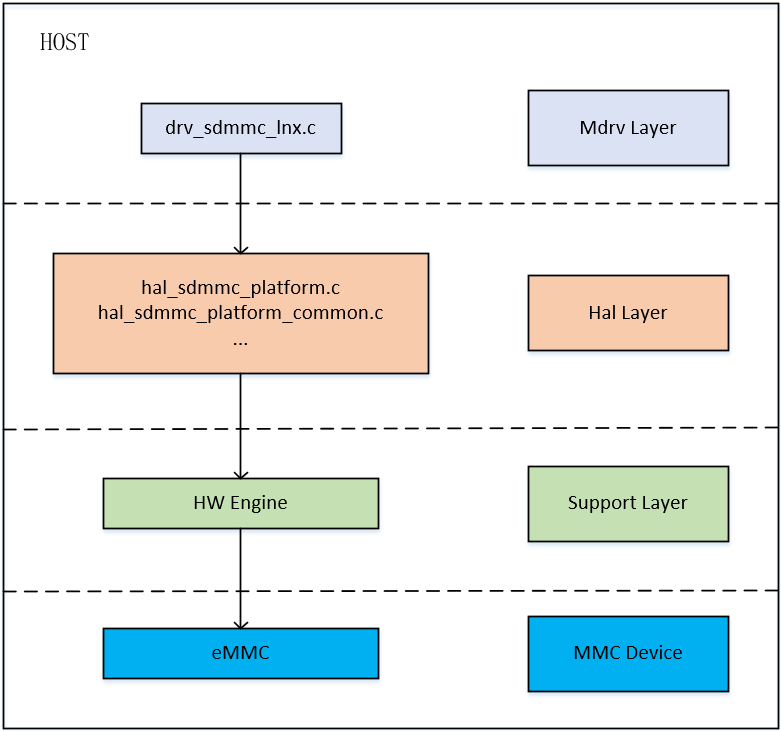
The overall framework of the eMMC host layer features three layers, namely the MDrv layer, the Hal layer, the Support layer, and the MMC device connected to the Support layer. The functions of each layer are as follows:
Mdrv Layer:
The Mdrv layer of eMMC mainly completes the operation of registering the Host with the core layer. It also provides some additional encapsulation interfaces, such as eMMC_bootbus and set_sdmmc_driving_control, for the user layer to set or obtain the status of the Engine and the card. It completes the MIE interrupt registration to ensure the normal reception and transmission of subsequent signals.
Hal Layer:
In the Hal layer of eMMC, hal_sdmmc_v5.c realizes signal transmission by reading and writing registers, while hal_sdmmc_platform_common.c determines which set of pad pins the Host Engine is connected to, and performs pull-up and pull-down operations. Finally, hal_sdmmc_intr.c file is the interface related to interrupt and time processing.
Support Layer:
This layer belongs to the layer of hardware support. The final implementation related to the driver requires hardware support.
MMC device:
MMC devices, such as eMMC cards, are directly connected to the hardware support of the driver and are the final operation object of the driver.
2. KEYWORD
IP: The Host Engine which eMMC devices are connecting to.
IP bank: The register address of Host Engine that drives eMMC devices.
HS: High-speed Interface Timing Mode as fast as 25MB/S, 50MHz Single Data Rate Bus, 3.3V is required.
HS200: High-speed Interface Timing Mode as fast as 200MB/S, 200MHz Single Data Rate Bus, 1.8V is required.
HS400: High-speed DDR Interface Timing Mode as fast as 400MB/S, 200MHz Double Data Rate Bus, 1.8V is required.
3. FUNCTION DESCRIPTION
| Package | eMMC Number | Bus Bandwidth | Clock Range | uboot Data Transmission Mode | Kernel Data Transmission Mode | IP Bank | Product |
|---|---|---|---|---|---|---|---|
| BGA | 1 | 1, 4, 8 | 300k ~ 200M | DMA | ADMA | 0x1410 | souffle |
| BGA | 2 (ext.) | 1, 4 | 300k ~ 48M | DMA | ADMA | 0x1413 (non-pm) / 0x42 (pm) | iford |
Set Bus Bandwidth:
eMMC supports three bus bandwidth configurations: 1 — 1-bit mode, 4 — 4-bit mode, and 8 — 8-bit mode. You may set the configuration by modifying the bus-width parameter in the device tree.
Set Clock:
eMMC driver supports the configuration of clock range between 300KHz to 200MHz. You may set the largest clock range by modifying the max-frequency parameter in the device tree. The final clock frequency will be the largest frequency supported by the current bus speed.
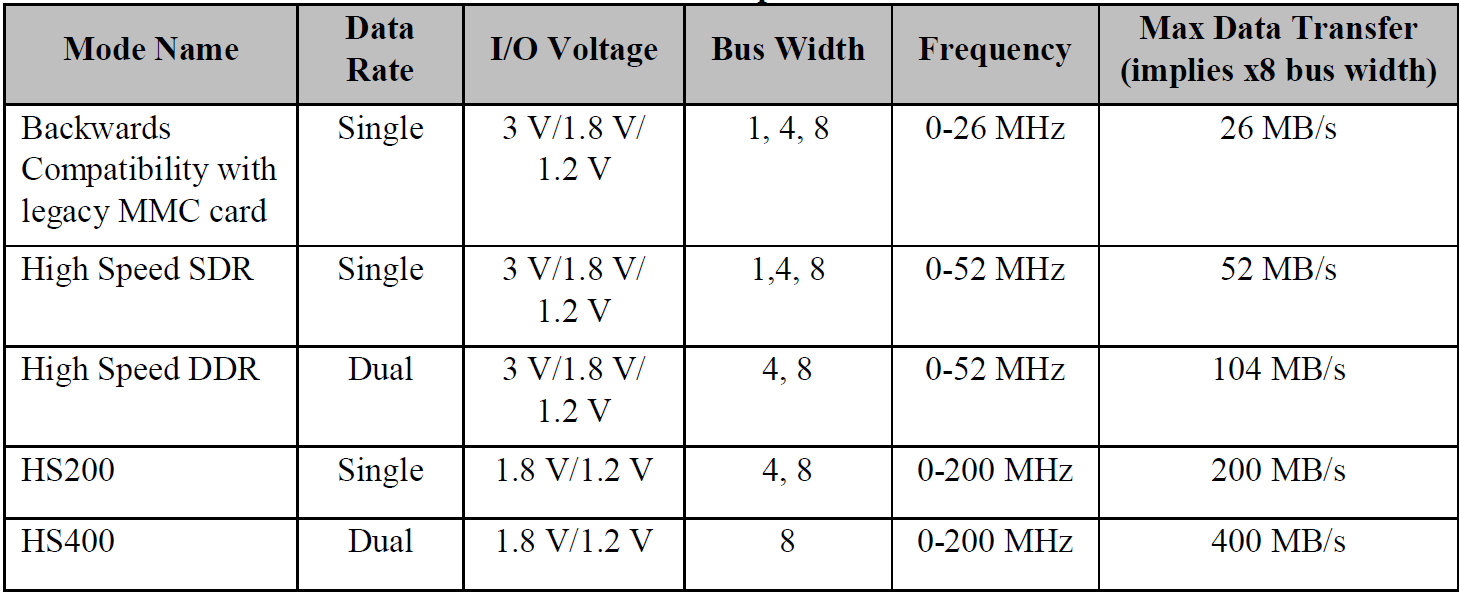
The configuration of different bus bandwidths and clock frequencies will affect the speed of data transmission. eMMC 5.0 supports HS200 and HS400 speed mode. To use it, you can enable mmc-hs200-1_8v/mmc-hs400-1_8v in the corresponding slot in the device tree.
Set Data Transmission Mode:
eMMC supports the configuration of two data transmission modes — DMA and ADMA — under kernel. ADMA mode is used by default.
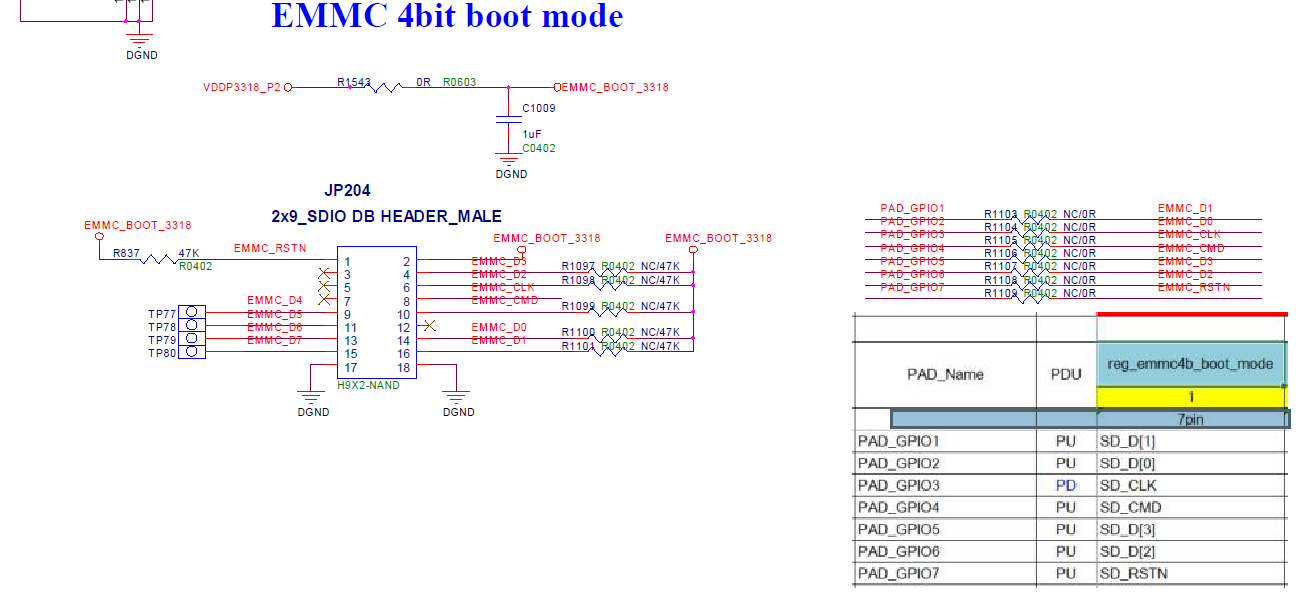
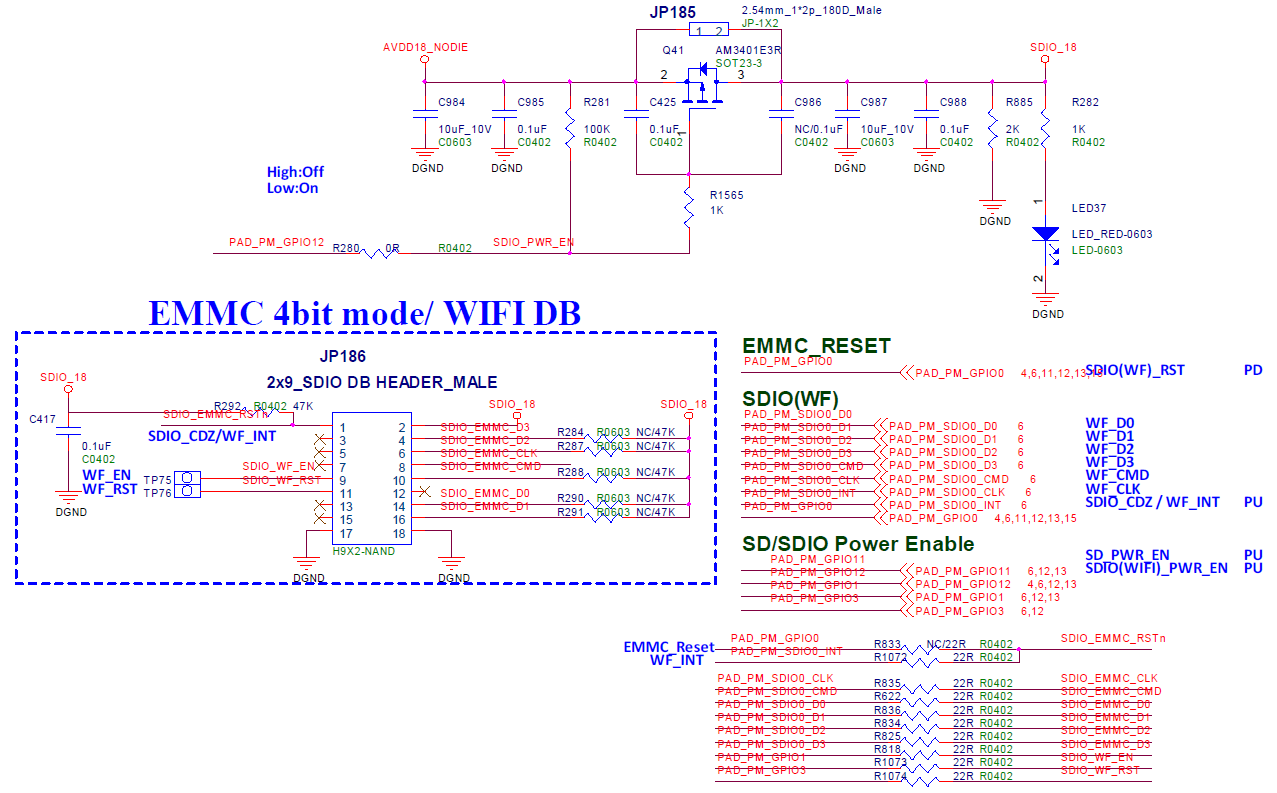
4. HARDWARE CONNECTION
5. Uboot USER GUIDE
5.1. uboot config Setting
1. make menuconfig
2. # SigmaStar drivers -->
3. #    <*> SigmaStar mmc host
Under uboot, eMMC driver is located in drivers/sstar/mmc_host/ directory. To compile the file, you will need to enable SSTAR_MMC_HOST compile function by entering the command above.
5.2. Dts Parameter Configuration
You may set the basic parameters of driver in the Host layer by configuring sstar_mmc1 in dtsi. The parameters in dtsi are set out below:
sstar_mmc1: sstar_mmc1 {
            compatible = "sstar-mmc";

            bus-width = <4>;
            max-frequency = <48000000>;
            cap-mmc-highspeed = <1>;
            ip-order = <0>;
            pad-orders = <3>;
            pwr-on-delay = <10>;
            pwr-off-delay = <50>;
            fack-cdz = <0>;
            rev-cdz = <0>;
            clk-driving  = <1>; //0~7
            cmd-driving  = <1>; //0~7
            data-driving = <1>; //0~7
            en-clk-phase = <0>; //0/1
            rx-clk-phase = <0>; //0-3
            tx-clk-phase = <0>; //0-3
            non-removable = <1>;
            status = "okay";
        };
The description of parameters are set out below:
| Parameter | Description | Note |
|---|---|---|
| bus-width | Configure the bus width of card slot. | 4 – 4bit mode |
| max-frequency | Configure the maximum clock frequency supported by the corresponding card slot. | The maximum clock frequency supported by iford is 48MHz |
| ip-order | Configure the IP number of the corresponding card slot. | |
| pad-order | Designate the pad to be connected to the card. | Value range: (0,1,2), iford eMMC mode value range: (3,4,5) |
| pwr-on-delay | Configure the power-on delay time of each card slot in the unit of ms. | SDIO device normally needs to have delay time configured so as to facilitate SDIO device loading firmware and reaching ready status. Please follow the suggestion of SDIO device manufacturers for the exact delay time needed. |
| pwr-off-delay | Configure the power-off delay time of each card slot in the unit of ms. | |
| fake-cdz | Configure whether card detection should be ignored. Setting this parameter to 1 indicates that card insertion is recognized by default. | Card detection is suggested to be configured to 1 for certain SDIO devices that are fixed to the board. |
| rev-cdz | This parameter can be configured to reverse the card detection condition for the current board. | |
| clk-driving | Configure the driving capacity of clock pad pin for the corresponding card slot. | Value range: 0 ~ 7 (iford: 0 ~ 3) |
| cmd-driving | Configure the driving capacity of command pad pin for the corresponding card slot. | Value range: 0 ~ 7 (iford: 0 ~ 3) |
| data-driving | Configure the driving capacity of data[3:0] pad pin for the corresponding card slot. | Value range: 0 ~ 7 (iford: 0 ~ 3) |
| en-clk_phase | Configure whether clock phase tuning should be enabled for the corresponding card slot. | |
| rx-clk_phase | Configure the phase of clock tx for the corresponding card slot. | Value range: 0-3, this parameter takes effect when en-clk_phase is set to 1. |
| tx-clk_phase | Configure the phase of clock rx for the corresponding card slot. | Value range: 0-3, this parameter takes effect when en-clk_phase is set to 1. |
| non-removable | Configure whether the device cannot be removed. | Set to 1 to indicate that the device is non-removable. |
5.3. Uboot cmd Parameter Description
(1) emmc create
Format:
emmc create [name] [size]
Description: Create partition. "name" represents the name of partition, while size indicates its size (Bytes).
Example: To create a partition named p1 in the size of 10M —
emmc create p1 0xA00000
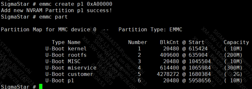
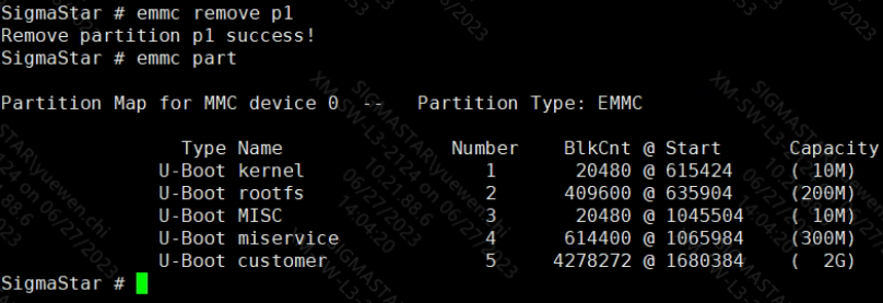
(2) emmc part
Description: Show partition in the following format: #Partition Name# #Partition Number# #Size@Offset (the occupied space) (The unit of size and offset is block)# #The occupied space in the unit of MBytes#
Example:
SigmaStar # emmc part
              U-Boot kernela               1       20480 @ 615200     ( 10M)
              U-Boot rootfsa               2      409600 @ 635680     (200M)
              U-Boot usera                 3      614400 @ 1045280    (300M)
              U-Boot data                  4     4298752 @ 1659680    (  2G)
(3) emmc remove
Format:
emmc remove [name]
Description: Delete the partition by its name
Example: Delete p1 partition —
emmc remove p1
(4) emmc rmgpt
Format:
emmc rmgpt
Description: Delete all partitions of UDA. The partition data will be removed by partition table, but the UDA partition will not be erased.
(5) emmc read.p
Format:
emmc read.p [addr][partition_name][size]
Description: Read the partition data into the memory. Addr refers to the memory address, partition_nam refers to the partition name, and size refers to the copied data size (Bytes).
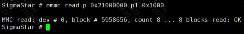
Example: Copy 0x1000Bytes data at the beginning of p1 to memory 0x21000000 —
emmc read.p 0x21000000 p1 0x1000
(6) emmc write.p
Format:
emmc write.p [addr][partition_name][size]
Description: Write memory data into the eMMC partition. Addr refers to the memory address, partition_nam refers to the partition name, and size refers to the copied data size (Bytes)
Example: Copy 0x1000Bytes data at the beginning of memory 0x21000000 to eMMC p1 partition —
emmc write.p 0x21000000 p1 0x1000
(7) emmc write.p.continue
Format:
emmc write.p.continue [addr] [partition_name] [offset] [size]
Description: Write memory data to the offset address of the partition. "[offset]" refers to the offset address of the partition (block unit), and the size refers to the size of the copied data (Bytes).
Example: Consecutively copy three divided files (in the size of 10M, 20M, and 10M, respectively) to partition p1
emmc write.p.continue 0x21000000 p1 0x0 0xA00000 //Copy 0xA00000 Bytes data to the initial address of p1
emmc write.p.continue 0x21000000 p1 0x5000 0x1400000 //0x5000=0xA00000/512
emmc write.p.continue 0x21000000 p1 0xF000 0xA00000 //0xF000=0x5000+0x1400000/512
(8) emmc read.p.continue
Format:
emmc read.p.continue [addr] [partition_name] [offset] [size]
Description: Copy the data from the partition offset to memory.
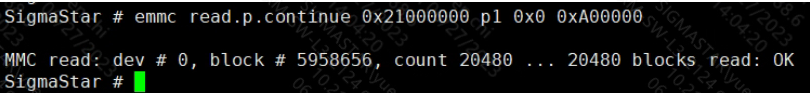
emmc read.p.continue 0x21000000 p1 0x0 0xA00000
(9) emmc erase.p
Format:
emmc erase.p [name]
Description: Format designated partition.
Example: Format the data of p1 partition. After formatting is completed, partition data will be 0.
emmc erase.p p1
(10) emmc erase
Format:
emmc erase
Description: Erase the entire current partition. If, for instance, you are currently dealing with UDA partition, this function will erase the entire UDA partion. BE VERY CAREFUL.
5.4. Uboot cmd Usage
(1) Create a new partition named p1 in the size of 10M
(2) Copy 0x1000Bytes data at the beginning of p1 to memory 0x21000000
(3) Copy 0xA00000 from 0x0 of partition p1 to memory 0x21000000
(4) Erase data in p1 partition
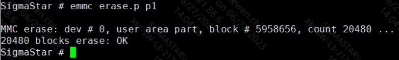
(5) Erase partition p1
6. Kernel USER GUIDE
6.1. Kernel Config Configuration
1. Related Driver Module
The Card layer (mmc_block.ko) and the Core layer (mmc_host.ko) use standard linux code. The Host layer (kdrv_sdmmc.ko) is maintained by SigmaStar. You can choose to compile them into the kernel or compile them as ko files in menuconfig.
2. Driver Modules Corresponding to enable
1. make menuconfig
2. # Device Drivers -->
3. #    <*> MMC/SD/SDIO card support -->                   (mmc_core.ko)
4. #        <*> MMC block device driver                    (mmc_block.ko)
5. #    [*] SStar SoC platform drivers -->
6. #        <*> SStar SD/MMC Card Interface Support        (kdrv_sdmmc.ko)
7. #        [ ]     Support SD30
8. #        [ ]     Support EMMC50
9. #        [*]     Support SDMMC Command
10.#        [*]       Support SDMMC UT verify
6.2. Dts Parameter Configuration
You may set the basic parameters of driver in the Host layer by configuring sstar_sdmmc0 in dtsi. The parameters in dtsi are set out below:
sstar_sdmmc0: sstar_sdmmc0 {
            compatible = "sstar,sdmmc";

            bus-width = <4>;
            max-frequency = <48000000>;
            non-removable;
            broken-cd;
            cap-mmc-highspeed;
            mmc-hs200-1_8v;
            mmc-hs400-1_8v;
            no-sdio;
            no-sd;
            //no-mmc;
            reg = <0x1F008400 0x200>;
            pll-reg = <0x1F283200 0x200>;
            cifd-reg = <0x1F008600 0x200>;
            pwr-save-reg = <0x1F008800 0x200>;
            ip-order = /bits/ 8 <1>;
            pad-order = /bits/ 8 <0>;
            trans-mode = /bits/ 8 <1>;
            fake-cdz = /bits/ 8 <0>;
            rev-cdz = /bits/ 8 <0>;
            pwr-on-delay = <1>;
            pwr-off-delay = <30>;
            support-cmd23 = /bits/ 8 <1>;
            clk-driving = <2>;
            cmd-driving = <2>;
            data-driving = <2>;
            en-clk-phase = /bits/ 8 <0>; //0/1
            rx-clk-phase = <0>; //0-3
            tx-clk-phase = <0>; //0-3
            en-eight-phase = /bits/ 8 <0>; //0/1
            rx-eight-phase = /bits/ 8 <0>; //0/1
            tx-eight-phase = /bits/ 8 <0>; //0/1
            interrupts = <GIC_SPI INT_IRQ_SD IRQ_TYPE_LEVEL_HIGH>,
                        <GIC_SPI INT_IRQ_SDIO IRQ_TYPE_LEVEL_HIGH>;
            interrupt-names = "mie0_irq", "mie1_irq";
            clocks = <&CLK_sd>;
            clock-names = "clk_sdmmc1";
            status = "ok";
    };
As shown by the figure above, the explanation of eMMC device tree configuration nodes is set out below:
| Parameter | Description | Note |
|---|---|---|
| bus-width | Configure the buswidth of the corresponding card slot | 4 - 4bit mode |
| max-frequency | Configure the maximum clock frequency supported by the corresponding card slot | The maximum clock frequency supported by iford is 48MHz |
| non-removable | Configure whether the device cannot be removed. Set to 1 to indicate that the device is non-removable by default. | eMMC/SDIO devices are generally set as non-removable |
| broken-cd | Configure whether to use cdz interrupt | Not used in eMMC device |
| cap-mmc-highspeed | Configure whether the device supports highspeed bus speed mode | Highspeed mode support is enabled by default |
| mmc-hs200-1_8v | Configure whether to enable hs200 bus speed mode | Not used in iford |
| mmc-hs400-1_8v | Configure whether or enable hs400 bus speed mode | Not used in iford |
| no-sdio | Configure whether the device supports SDIO protocol or not | eMMC device does not support SDIO protocol |
| no-sd | Configure whether the device supports SD protocol or not | eMMC device does not support SD protocol |
| reg | Configure eMMC Host Engine Bank address | Use according to the 'Function Description' |
| pll-reg | Configure eMMC Host Engine PLL Bank address | Not used in iford, just keep the default value |
| cifd-reg | Configure eMMC Host Engine CIFD Bank address | eMMC Host supports adma/dma/cifd data transmission mode. Among them, adma is recommended. |
| pwr-save-reg | Configure eMMC Host Engine PSM Bank address | eMMC Host supports IP-level power failure protection function |
| ip-order | Configure the IP number of the corresponding card slot | Currently iford supports 0, 1 |
| pad-order | Configure the padmux mode number of the corresponding card slot | Configure padmux mode according to actual hardware |
| trans-mode | Configure the data transmission mode of the corresponding card slot | Not used in iford; adma is used by default |
| fake-cdz | Configure whether the corresponding card slot should ignore Card Detection | Not used in eMMC, just keep the default value |
| rev-cdz | Configure CDZ detection direction | Not used in eMMC, just keep the default value |
| pwr-on-delay | Configure the power-on delay time of the corresponding card slot | Not used in eMMC, just keep the default value |
| pwr-off-delay | Configure the power-off delay time of the corresponding card slot | Not used in eMMC, just keep the default value |
| support-cmd23 | Configure whether to support the preset transmission block number function | cmd23 support is enabled by default |
| clk-driving | Configure the driving of the clock line corresponding to the card slot | Value range: 0 ~ 7 (iford: 0 ~ 3) |
| cmd-driving | Configure the driving of the cmd line corresponding to the card slot | Value range: 0 ~ 7 (iford: 0 ~ 3) |
| data-driving | Configure the driving of the data line corresponding to the card slot | Value range: 0 ~ 7 (iford: 0 ~ 3) |
| en-clk-phase | Configure whether to enable clock phase tuning for the corresponding card slot | 0 - Disabled / 1 - Enabled |
| rx-clk-phase | Configure the clock rx phase of the corresponding card slot | Value range: 0-3, this parameter takes effect when en-clk-phase is set to 1. |
| tx-clk-phase | Configure the clock tx phase of the corresponding card slot | Value range: 0-3, this parameter takes effect when en-clk-phase is set to 1. |
| en-eight-phase | Configure whether to enable clock 8 phase tuning for the corresponding card slot | 0 - Disabled / 1 - Enabled; not used in iford |
| rx-eight-phase | Configure the clock rx phase of the corresponding card slot | Value range: 0-5, this parameter takes effect whenen-eight-phase is set to 1. |
| tx-eight-phase | Configure the clock tx phase of the corresponding card slot | Value range: 0-5, this parameter takes effect whenen-eight-phase is set to 1. |
| interrupts | Configure the interrupt information | Just keep the default value |
| interrupt-names | Configure the interrupt names | Used in combination with interrupts |
| clocks | Configure the clock source of eMMC Host Engine | Just keep the default value |
| clock-names | Configure the name of the clock source | Used in combination with clocks |
In order to facilitate the unified management of padmux, eMMC driver also supports using padmux.dtsi to configure the pad group to be used. When padmux.dtsi has PUSE about eMMC or SDMMC, the driver will use this method to configure padmux first. This method can intuitively find out whether there is a pad conflict with other modules. Examples are as follows:
1.    padmux {
2.        compatible = "sstar-padmux";
3.        schematic =
4.            //EMMC0
5.            <PAD_GPIO1             PINMUX_FOR_EMMC4B_MODE_1        MDRV_PUSE_SDIO0_D1>,
6.            <PAD_GPIO2             PINMUX_FOR_EMMC4B_MODE_1        MDRV_PUSE_SDIO0_D0>,
7.            <PAD_GPIO3             PINMUX_FOR_EMMC4B_MODE_1        MDRV_PUSE_SDIO0_CLK>,
8.            <PAD_GPIO4             PINMUX_FOR_EMMC4B_MODE_1        MDRV_PUSE_SDIO0_CMD>,
9.            <PAD_GPIO5             PINMUX_FOR_EMMC4B_MODE_1        MDRV_PUSE_SDIO0_D3>,
10.           <PAD_GPIO6             PINMUX_FOR_EMMC4B_MODE_1        MDRV_PUSE_SDIO0_D2>,
11.           <PAD_PM_GPIO11         PINMUX_FOR_GPIO_MODE            MDRV_PUSE_SDIO0_PWR>,
12.           <PAD_GPIO7             PINMUX_FOR_EMMC_RST_MODE_1      MDRV_PUSE_SDIO0_CDZ>,
13.    };
Depending on the actual use case, you may replace the PAD name in the first column and the second group of pad modes corresponding to the pad.
6.3. Sample code
N/A.
6.4. Module User Guide
After the Linux system starts, the eMMC driver is loaded normally and the eMMC Card is recognized, the corresponding block device node /dev/mmcblk* will be created. Use fdisk, mkfs, mount and dd tools to apply for partitions on MMC devices, format partitions, mount partitions, and read and write the mounted partitions.
In addition, the driver also provides sysfs for debugging. After entering the /sys/devices/soc0/soc/{reg}.sstar_sdmmc0 directory, you can perform the operation intended.
1.  cd /sys/devices/soc0/soc/{reg}.sstar_sdmmc0
2.
3.  # View the eMMC Host clock frequency
4.  cat debug_get_sdmmc_clock
5.
6.  # Check the last communication status between eMMC Host and Device
7.  cat debug_get_sdmmc_status
8.
9.  # Set the [slotNo] emmc bootbus value
10. echo [slotNo] [bootbus] > eMMC_bootbus
11. # Check the emmc bootbus value of all slots
12. cat eMMC_bootbus
13.
14. # Specify the starting position and Block count to erase the eMMC Device
15. echo [startblkAddr] [blkcnt] > eMMC_erase
16.
17. # Set the [slotNo] eMMC Device to support HW reset
18. echo [slotNo] > eMMC_hwreset
19. # Check if eMMC Device enables HW reset support
20. cat eMMC_hwreset
21.
22. # Set the eMMC Device boot partition
23. echo [partconf] > eMMC_partconf
24. #[partconf] -0: don't support boot
25. #           -1: boot0 partition
26. #           -2: boot1 partition
27. #           -7: UDA
28. # Check the eMMC Device boot partition
29. cat eMMC_partconf
30.
31. # Set the eMMC write protect range (by group setting)
32. echo [otption] [address] <size> > eMMC_write_protect
33. #[option] -0: Set the eMMC address of the group to be 'write protect'
34. #         -1: Clear the eMMC address of the group remove 'write protect'
35. #         -2: Ask the eMMC address of the group whether it's in 'write protect'?
36. #         -3: ASK the eMMC address of the group about the 'write protect' type
37. #[address]  Unit: block
38. #[size]     Unit: block
39.
40. # Set the eMMC bus width
41. echo [buswidth] > sdmmc_bus_width_set
42. #[buswidth] -2: 4bit buswidth
43. #           -3: 8bit buswidth(iford not support)
44. #           -others: invalid
45.
46. # Set the eMMC clock and Timing mode
47. echo [clk_freq] > sdmmc_clk_timing_set
48. #[clk_freq] Unit: Hz
49. # -[0,12MHz): set clock only
50. # -[12MHz, 26MHz]: set timing to MMC_TIMING_LEGACY and set clock
51. # -(26MHz, 50MHz): set timing to MMC_TIMING_MMC_HS and set clock
52.
53. # Set the eMMC Host to use interrupt or polling mode
54. echo [intr_en] > sdmmc_inter_polling_set
55. #[intr_en] -0: polling mode
56. #          -1: interrupt mode
57. # Tips: If the eMMC Host is already working in polling mode, you cannot switch to interrupt mode.
58.
59. # Perform HW reset on [slotNo] eMMC Device
60. echo [slotNo] > sdmmc_reset
61. # iford not support
62.
63. # Set the eMMC pin driving strength
64. echo [slotIndex] [signalLine] [drvLevel] > set_sdmmc_driving_control
65. echo [slotIndex]  [drvLevel] > set_sdmmc_driving_control
66. echo [signalLine] [drvLevel] > set_sdmmc_driving_control
67. echo [drvLevel] > set_sdmmc_driving_control
68. #[slotIndex]: 0-1
69. #[signalLine]: "clk"/"cmd"/"data"/"all"
70. #[drvLevel]: 0-7 (iford support 0-3)
6.5 eMMC Driving Capability Configuration
6.5.1 Driving Capability Configured by sysfs
eMMC driver provides sysfs control pin driving capability, please refer to the following instruction:
1. cd /sys/devices/soc0/soc/<reg>:sstar_sdmmc[i]
2. # <reg> - Generate Reg value based on the actual configuration information of DTSI
3. # [i]   - Generate index value based on the actual configuration information of DTSI
4. echo [slotNo] <signal> [level] > set_sdmmc_driving_control
5. # Set driving capability as [level] for the signal line <signal> of [slotNo].
6. # [slotNo] - Select the slot to be operated.
7. # <signal> - You may choose to set clk, cmd, data, all, or null (equal to all).
8. # [level]  - driving capability level. Value range: 0 ~ 4.
Set the driving capability of the four data pins of emmc to 1:
1. cd / sys/devices/soc0/soc/1f008400.sstar_sdmmc0
2. echo 1 data 1 > set_sdmmc_driving_control
6.5.2 Driving Capability Configured by dts
eMMC driver supports configuring the driving capabilities of clk, cmd and data signal lines from dts. The configuration is as follows:
1. sstar_sdmmc0: sstar_sdmmc0 {
2.     compatible = "sstar,sdmmc";
3.     bus-width = <4>;
4.     no-sdio;
5.     no-sd;
6.     …
7.     clk-driving = <2>;
8.     cmd-driving = <2>;
9.     data-driving = <2>;
10.    …
11. }

1. sstar_sdmmc1: sstar_sdmmc1 {
2.     compatible = "sstar,sdmmc";
3.     bus-width = <4>;
4.     no-mmc;
5.     …
6.     clk-driving = <1>;
7.     cmd-driving = <1>;
8.     data-driving = <1>;
9.    …
10. }
As shown above, these three attribute parameters configure the driving capabilities of the clk line, cmd line and four data lines, respectively.
7. API Reference
To use the following interfaces provided by this function module, the configuration option CONFIG_SUPPORT_SDMMC_COMMAND should be enabled:
| API Name | Function |
|---|---|
| SDMMC_Init | Initialize eMMC driver and recognize device. |
| SDMMC_WriteData | Write data to eMMC device. |
| SDMMC_ReadData | Read data from eMMC device. |
| eMMC_EraseBlock | Erase the designated data in eMMC device. |
| eMMC_GetExtCSD | Get the content of ExtCSD register in eMMC device. |
7.1. SDMMC_Init
-
Purpose
Initialize eMMC driver and recognize device.
-
Syntax
U16_T SDMMC_Init(struct sstar_sdmmc_slot *p_sdmmc_slot)
-
Parameter
Parameter Name Description p_sdmmc_slot The control block corresponding to eMMC, which is generated during driver registration and added to the mmc_host private variable. -
Return Value
Return Value Description 0 Successful. other Failed.
7.2. SDMMC_WriteData
-
Purpose
Write data to eMMC device.
-
Syntax
U16_T SDMMC_WriteData(struct sstar_sdmmc_slot *p_sdmmc_slot, U32_T u32CardBlkAddr, U16_T u16BlkCnt, U8_T *pu8DataBuf)
-
Parameter
Parameter Name Description p_sdmmc_slot The control block corresponding to eMMC, which is generated during driver registration and added to the mmc_host private variable. u32CardBlkAddr The Block address written to eMMC u16BlkCnt The Block count written pu8DataBuf The data buffer address to be written -
Return Value
Return Value Description 0 Successful. other Failed.
7.3. SDMMC_ReadData
-
Purpose
Read data from eMMC device.
-
Syntax
U16_T SDMMC_ReadData(struct sstar_sdmmc_slot *p_sdmmc_slot, U32_T u32CardBlkAddr, U16_T u16BlkCnt, U8_T *pu8DataBuf)
-
Parameter
Parameter Name Description p_sdmmc_slot The control block corresponding to eMMC, which is generated during driver registration and added to the mmc_host private variable. u32CardBlkAddr The Block address read from eMMC u16BlkCnt The Block count read pu8DataBuf The data buffer address for storing data -
Return Value
Return Value Description 0 Successful. other Failed.
7.4. eMMC_EraseBlock
-
Purpose
Erase the data at a designated address in eMMC.
-
Syntax
U16_T eMMC_EraseBlock(struct sstar_sdmmc_slot *p_sdmmc_slot, U32_T u32BlkAddrStart, U32_T u32BlkAddrEnd)
-
Parameter
Parameter Name Description p_sdmmc_slot The control block corresponding to eMMC, which is generated during driver registration and added to the mmc_host private variable. u32BlkAddrStar The starting address for erasing. u32BlkAddrEnd The ending address for erasing. -
Return Value
Return Value Description 0 Successful. other Failed.
7.5. eMMC_GetExtCSD
-
Purpose
Get the content of ExtCSD register in eMMC device.
-
Syntax
U16_T eMMC_GetExtCSD(struct sstar_sdmmc_slot *p_sdmmc_slot, U8_T *pu8DataBuf)
-
Parameter
Parameter Name Description p_sdmmc_slot The control block corresponding to eMMC, which is generated during driver registration and added to the mmc_host private variable. pu8DataBuf The buffer address where ExtCSD is kept. -
Return Value
Return Value Description 0 Successful. other Failed.
8. Debug & FAQ
The actual problems related to eMMC card usage can be divided into the following types:
1. Identification card failed.
If card identification failed, you need to determine whether the problem is response failed to be obtained or the transmission signal is bad, which indicates a CRC problem. The problem can be identified by capturing the waveform. The specific difference and the debugging method are as follows:
-
Response failed to be obtained.
Phenomenon: There are only commands sent by the host on the waveform, but no response returned by the device.
Debug method: First, check voltage and clock, and then check whether a command is sent out on the waveform. If there is no problem with the first two, then check whether the card answers the response. If there is no response, check the device status.
-
The signal is bad and there is a CRC problem
Phenomenon: If the waveform shows the command and response to be normal, you may need to consider that there is a CRC problem.
Debug method: If there is a CRC problem, you need to first rule out hardware problems, such as: whether the device is properly connected, whether external interference exists, etc. After that, try to change the driving level in dts, if there are still problems, you need to consider adjusting the clock phase.
2. Reading and writing failed.
If you encounter problems during normal reading and writing process, you need to determine whether it is a reading and writing timeout problem, or the problem is with CRC due to bad signals. The problem can be identified by looking up the log. The timeout problem will show timeout. The debugging method is as follows:
-
Reading and writing timeout
Phenomenon: The word timeout shows up in the error log.
Debug method: First, you need to determine whether the current clock frequency and bus width are the expected configuration values. Second, you can try to increase the timeout time in the driver. If there is still a timeout problem, you need to capture the waveform for further analysis.
-
The signal is bad and there is a CRC problem
Phenomenon: If the above problems can be excluded, the problem may be with CRC.
Debug method: Please refer to the previous section for the debug method. In addition, if speed is not of primary concern, you may consider lowering the frequency or reducing the bus width.