IS(Image Stabilization) DEBUG SOP
REVISION HISTORY
| Revision No. | Description |
Date |
|---|---|---|
| 1.00 | 12/13/2023 | |
| 08/11/2025 |
1. Introduction
This document primarily records troubleshooting or investigation methods for common issues encountered when using image stabilization functions.
- Note:
- The image stabilization function is located in the MI_LDC module, which is divided into two main categories: DIS-GME (DIS, Digital Image Stabilization) and DIS-GYRO (EIS, Electronic Image Stabilization).
2. Problem Quick Index List
3. Common Issues in DIS-GME Mode
3.1 DIS Processing Flow Stuck
In the software processing flow, the main logic responsible for image stabilization processing is located in the DIS PASS (i.e., pass0 in the MI_LDC module).
3.1.1 Phenomenon
When this situation occurs, it is generally accompanied by frame drops, no stream, and the following logs:
# Case 1: output task stuck
[MI WRN] _MI_SYS_Pass_TryDequeueOutputTaskNoLock[6154]:  [thread:ldc0_P0_MAIN] mod[23] dev[0] pass[0] chn[0] output not finished more than 5000ms;
[MI WRN] _MI_SYS_Pass_DebugDumpOutputTaskFence[371]: [0:c71dbe00 0000000d] fence39
# Case 2: input task stuck
[MI WRN] _MI_SYS_Pass_TryDequeueInputTaskNoLock[3325]:  [thread:ldc0_P0_MAIN] mod[23] dev[0] pass[0] chn[0] inputtask's fence not finished more than 5000ms;
[MI WRN] _MI_SYS_Pass_TryDequeueInputTaskNoLock[3391]:  [thread:ldc0_P0_MAIN] mod[23] dev[0] pass[0] chn[0] inputtask CheckInputTaskStatus failed more than 5000ms,total pending task32;
3.1.2 Troubleshooting Direction
STEP1: Investigate deadlock possibility
- Execute
echo show_threads > /proc/mi_modules/mi_ldc/mi_ldc0; - Check if there are LDC/DIS APIs constantly waiting for locks or semaphores in the log;
STEP2: Investigate hardware hang possibility
- Execute
/customer/riux32_r 0x1b24; - Check if the value at offset 0x11 is too large. If there is a value in the tens of millions, it is likely a hardware hang;
STEP3: Investigate software hang possibility
- Execute
echo 7 > /proc/mi_modules/mi_ldc/debug_level; - Check if there are abnormalities in the ldc log, such as repeatedly printing the same sentence or the same type of log (indicating being in a loop);
STEP4: If the above steps cannot resolve the issue
- Collect the execution logs of the above steps and provide them to the module owner;
- Execute
cat /proc/mi_modules/mi_ldc/mi_ldc0, save the log and provide it to the module owner; - Describe the customer scenario, such as frame rate, resolution, module channel usage;
3.2 CMDQ Timeout
When encountering this problem, as it may be related to hardware or issued commands, please ask FAE colleagues to capture logs for the module owner to analyze. Specific steps are as follows.
3.2.1 Phenomenon
When this problem is triggered, first confirm whether DIS scenario is being used, and second whether the CMDQ ID is CVS_TRIG. The phenomenon is as follows:
<3>[CMDQ]cmdq(4)[35m ERR: WAIT_TRIG_TIMEOUT [m(0x00000400)
<3>[CMDQ][35mCmd data = 0x2000 : 0x0000 : 0x0000 : 0xFFFE
<3>[CMDQ][35mCmd:WAIT, dbg:0, adr:000000, dat:0000, mask:fffe
<3>[CMDQ][35mWait command timeout. Trigger_Bus Bit [0] Event [CVS_TRIG]
3.2.2 Log Capture Steps
STEP1: disable cmdq reset option
Execute the following commands. If already disabled, proceed directly to STEP3 when the problem is triggered:
vi /config/modparam.json; # Add "bEnableCmdqReset":0 content to sys node
sync;
reboot; # Or execute echo /config/modparam.json > /proc/mi_modules/mi_common/modparam
STEP2: Re-run app, wait for problem to reproduce, preserve the scene
STEP3: Execute the following commands to capture logs for module owner
#!/bin/bash
for((i=0;i<5;i+=1));
do
    /customer/riux32_r 0x1038;
    /customer/riux32_r 0x1b24;
    cat /proc/mi_modules/mi_ldc/mi_ldc0;
done
3.3 CVS_R / CVS_W MIU HitAddress or MMU Callback
When encountering this problem, as it may be related to actual timing, please ask FAE colleagues to capture logs according to the following steps for the module owner to analyze.
3.3.1 Phenomenon
When this problem is triggered, first confirm whether DIS scenario is being used, and second whether the access ID is CVS_R/W. The phenomenon is as follows:
# Case 1: MMU Callback
[MI WRN] MI_SYS_Mma_MmuCallback[357]: [MI_SYS_Mma_MmuCallback] Status=0x4, PhyAddr=0x402c20000, ClientId=0x4c,Name=CVS_W      IsWrite=1
[MI WRN] MI_SYS_Mma_MmuCallback[357]: [MI_SYS_Mma_MmuCallback] Status=0x4, PhyAddr=0x402c20000, ClientId=0x4c,Name=CVS_R      IsWrite=1
# Case 2: MIU HitAddress
MIU0 Block:1 WR Client:CVS_W      ID:4-12 Hitted_Address(MIU):0x3ffe0000<->0x3ffe000f
MIU0 Block:1 WR Client:CVS_R      ID:4-12 Hitted_Address(MIU):0x3ffe0000<->0x3ffe000f
3.3.2 Log Capture Steps
STEP1: Modify modparam.json, enable debug MMU and disable miuprotect
vi /config/modparam.json; # Add "debugMmu":1,"g_bEnableMiuProtect":0 content to sys node
sync;
reboot; # Or execute echo /config/modparam.json > /proc/mi_modules/mi_common/modparam
STEP2: Execute the following commands to capture information for module owner
echo debug_mmu debug_log 1 23 > /proc/mi_modules/mi_sys/mi_sys0;
echo 7 > /proc/mi_modules/mi_ldc/debug_level;
3.4 Pixelation
When this problem is triggered, it is necessary to determine which level of module is responsible. If MI_LDC(DIS) is suspected, execute the following steps:
3.4.1 Phenomenon
When this problem occurs, black borders, green bars, etc. can generally be seen in the RTSP stream.
3.4.2 Troubleshooting Direction
STEP1: Dump MI_LDC input and output to confirm if there are issues
# Dump input task, dis passid=0, chnid needs to be confirmed with customer's actual scenario
# echo dumpinputtask [chnid, passid, cnt, path] > /proc/mi_modules/mi_ldc/mi_ldc0
echo dumpinputtask 0, 0, 2, /mnt > /proc/mi_modules/mi_ldc/mi_ldc0
# Dump output task, dis passid=0, chnid needs to be confirmed with customer's actual scenario
# echo dumpoutputtask [chnid, passid, cnt, path] > /proc/mi_modules/mi_ldc/mi_ldc0
echo dumpoutputtask 0, 0, 2, /mnt > /proc/mi_modules/mi_ldc/mi_ldc0
STEP2: If dumped input is already pixelated
MI_LDC problem can be ruled out. Use previous-level dump commands to locate the specific module;
STEP3: If dumped input is not pixelated but output is pixelated
It can be confirmed that it is an MI_LDC problem. Provide the dumped input and output with scenario to the module owner for analysis;
STEP4: If dumped input and output are not pixelated
MI_LDC problem can be ruled out. Use next-level dump commands to locate the specific module;
3.5 Ineffective Stabilization or Poor Stabilization Effect
This problem can first be analyzed and confirmed through the following directions. If still ineffective or there is no troubleshooting direction, provide the following complete information to the module owner for analysis:
-
Record the final effect video;
-
Record the complete logs during runtime, including serial port and telnet terminals;
-
Scenario description (e.g., pipeline, DIS-GME mode parameters set via MI_LDC interface, which can be obtained by executing
cat /proc/mi_module/mi_ldc/mi_ldc0at runtime).
3.5.1 Troubleshooting Direction
STEP1: Check input video quality and scenario
| Phenomenon | Possible Causes and Solutions |
|---|---|
| Output video has trailing and flickering | Check input video frame by frame for motion blur. If motion blur exists, adjust IQ to eliminate motion blur |
| Output video has no stabilization or distortion | 1. Check if the scene in input video lacks features (very low light, large object occlusion, etc. may cause lack of features) 2. Check if foreground and background in input video have obvious depth difference (large parallax) 3. Check if there is large moving foreground in the jittery input video 4. Check if input video has obvious rolling shutter |
STEP2: Check if the lens has obvious distortion
Video distortion also affects DIS effect. It is recommended to use a lens with minimal distortion, or perform distortion correction to eliminate the impact of video distortion on DIS effect. The following shows before and after distortion correction:
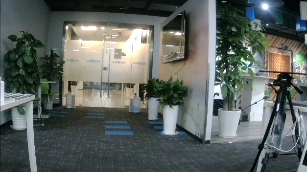
Distorted video frame |
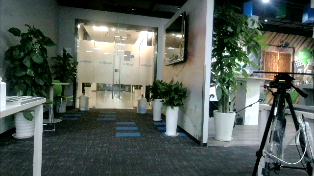
Video frame after distortion correction |
STEP3: Check if the lens has large parallax
Scenes with large parallax (i.e., foreground and background have obvious depth difference) may cause DIS output video distortion. Therefore, DIS is not recommended for scenes with large parallax.
Video frame with large parallax |
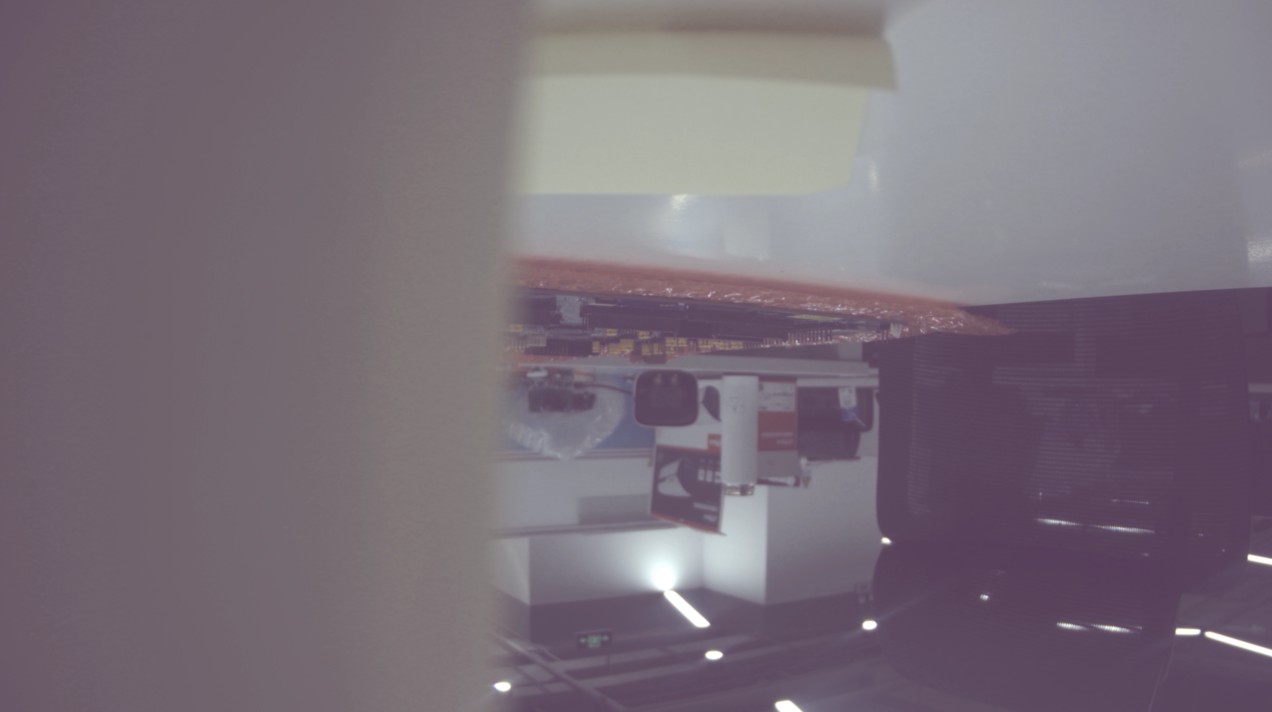
STEP4: Check if the scene is low-light
Within a certain low-light range, DIS can still work normally. However, in extremely low-light environments, DIS cannot detect feature points, resulting in poor effect. Therefore, DIS is not recommended for extremely low-light environments, as shown below:

Video frame in extremely low light |
-
Note:
At the start of streaming, the ISP module converges and by default drops 10 images. This process is from dark to bright. If convergence is insufficient, the brightness information of images sent to the DIS module may change (possibly still very dark), as shown below:
Video frame in extremely low light during ISP convergence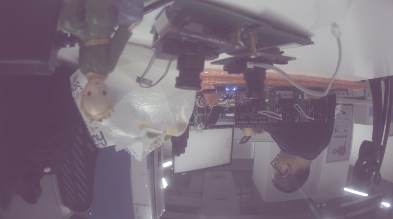
Video frame in low light during ISP convergence
4. Common Issues in DIS-GYRO Mode
4.1 DIS Processing Flow Stuck
In the software processing flow, the main logic responsible for image stabilization processing is located in the DIS PASS (i.e., pass0 in the MI_LDC module).
4.1.1 Phenomenon
When this situation occurs, it is generally accompanied by frame drops, no stream, and the following logs:
# Case 1: output task stuck
[MI WRN] _MI_SYS_Pass_TryDequeueOutputTaskNoLock[6154]:  [thread:ldc0_P0_MAIN] mod[23] dev[0] pass[0] chn[0] output not finished more than 5000ms;
[MI WRN] _MI_SYS_Pass_DebugDumpOutputTaskFence[371]: [0:c71dbe00 0000000d] fence39
# Case 2: input task stuck
[MI WRN] _MI_SYS_Pass_TryDequeueInputTaskNoLock[3325]:  [thread:ldc0_P0_MAIN] mod[23] dev[0] pass[0] chn[0] inputtask's fence not finished more than 5000ms;
[MI WRN] _MI_SYS_Pass_TryDequeueInputTaskNoLock[3391]:  [thread:ldc0_P0_MAIN] mod[23] dev[0] pass[0] chn[0] inputtask CheckInputTaskStatus failed more than 5000ms,total pending task32;
4.1.2 Troubleshooting Direction
STEP1: Investigate deadlock possibility
- Execute
echo show_threads > /proc/mi_modules/mi_ldc/mi_ldc0; - Check if there are LDC/DIS APIs constantly waiting for locks or semaphores in the log;
STEP2: Investigate software hang possibility
- Execute
echo 7 > /proc/mi_modules/mi_ldc/debug_level; - Check if there are abnormalities in the ldc log, such as repeatedly printing the same sentence or the same type of log (indicating being in a loop);
STEP3: If the above steps cannot resolve the issue
- Collect the execution logs of the above steps and provide them to the module owner;
- Execute
cat /proc/mi_modules/mi_ldc/mi_ldc0, save the log and provide it to the module owner; - Describe the customer scenario, such as frame rate, resolution, module channel usage;
4.2 "Gyro IS NOT Ready" Print Appears
4.2.1 Phenomenon
When this phenomenon occurs, it indicates that the FIFO DATA obtained from the GYRO peripheral (GYRO writes fixed data to the FIFO BUFFER at fixed time intervals according to the sampling rate setting) is already full:
[Warn]:Gyro not ready!!!!
- Note:
- When the APP first starts, about 6 lines of this log will be printed. This phenomenon is normal and the following steps do not need to be taken to troubleshoot the problem;
- If the log is printed continuously or intermittently, troubleshooting is required.
4.2.2 Troubleshooting Direction
STEP1: Investigate if there are frame drops or frame rate is too low
Since GYRO writes fixed data to the GYRO FIFO BUFFER at fixed time intervals according to the sampling rate setting, if the frame rate drops too much and data cannot be retrieved from the GYRO FIFO BUFFER in time, data will accumulate.
Execute cat /proc/mi_modules/mi_ldc/mi_ldc0 to check the overall frame rate of MI_LDC at this time, as shown below:

|
STEP2: Investigate if loose DuPont cable connection causes the transmitted data to be default maximum value
Re-plug the DuPont cable and try running the APP again;
STEP3: If the above steps cannot resolve the issue
- Collect the execution logs of the above steps and provide them to the module owner;
- Execute
cat /proc/mi_modules/mi_ldc/mi_ldc0, save the log and provide it to the module owner; - Describe the customer scenario, such as frame rate, resolution, module channel usage;
4.3 "GYRO_IOC_CMD_xxxxxxx fail" Print Appears
4.3.1 Phenomenon
When this situation occurs, it is generally accompanied by no stream and the following logs:
# Case 1: Getting accelerometer information failed
[MI ERR ]: _LDC_DISALGO_GYRO_Register[102]: {GYRO_IOC_CMD_GET_ACCEL_SENSITIVIVT} fail, ret:-1
[MI ERR ]: _LDC_DISALGO_GYRO_Register[102]: Gyro Get Sensitivity Fail
4.3.2 Troubleshooting Direction
STEP1: Investigate if incorrect DuPont cable connection is the cause
Check the GYRO DuPont cable connection. Since the GYRO Sensor board and Chip Board used by the customer may differ from the reference design, confirmation with the customer is required. It is best to obtain the GYRO Sensor schematic and actual board wiring diagram for confirmation.
STEP2: Investigate if the DuPont cable itself has open circuit or desoldering
- Try replacing the DuPont cable and running again, or use a multimeter to test the continuity of the DuPont cable;
- Try re-soldering and running again;
- Connect LA (logic analyzer) to view the waveform.
STEP3: If the above steps cannot resolve the issue
-
Collect the execution logs of the above steps and provide them to the module owner;
-
Provide the customer's dts configuration, gyro model, and gyro porting code to the module owner;
-
If possible, send the entire device to the module owner for analysis;
4.4 Pixelation
4.4.1 Phenomenon
When this problem occurs, black borders, green bars, etc. can generally be seen in the RTSP stream.
4.4.2 Troubleshooting Direction
STEP1: Dump MI_LDC input and output to confirm if there are issues
# Dump input task,dis passid=0
# echo dumpinputtask [chnid, passid, cnt, path] > /proc/mi_modules/mi_ldc/mi_ldc0
echo dumpinputtask 0, 0, 2, /mnt > /proc/mi_modules/mi_ldc/mi_ldc0
# Dump output task
# echo dumpoutputtask [chnid, passid, cnt, path] > /proc/mi_modules/mi_ldc/mi_ldc0
echo dumpoutputtask 0, 0, 2, /mnt > /proc/mi_modules/mi_ldc/mi_ldc0
STEP2: If dumped input is already pixelated
MI_LDC problem can be ruled out. Use previous-level dump commands to locate the specific module;
STEP3: If dumped input is not pixelated but output is pixelated
It can be confirmed that it is an MI_LDC problem. Provide the dumped input and output with scenario to the module owner for analysis;
STEP4: If dumped input and output are not pixelated
MI_LDC problem can be ruled out. Use next-level dump commands to locate the specific module;
4.5 Ineffective Stabilization or Poor Stabilization Effect
4.5.1 Troubleshooting Direction
This problem can first be analyzed and confirmed through the following directions. If still ineffective or there is no troubleshooting direction, provide the following complete information to the module owner for analysis:
-
Record the final effect video;
-
Record the complete logs during runtime, including serial port and telnet terminals;
-
Scenario description (e.g., pipeline, DIS-GYRO mode parameters set via MI_LDC interface, which can be obtained by executing
cat /proc/mi_module/mi_ldc/mi_ldc0at runtime).
STEP1: Check if GYRO peripheral is functioning normally
Check if the following problem prints appear in the serial port/telnet:
STEP2: Check if DISAttr parameter settings meet requirements
Refer to [IS User Guide] to check if as32RotationMatrix, u32FocalLengthX, and u32FocalLengthY parameter settings follow the rules.
4.6 Algorithm Error Log Troubleshooting
When algorithm error logs appear, prioritize troubleshooting according to the corresponding log chapter. If analysis based on the corresponding chapter content is ineffective, analyze according to the following standardized steps:
STEP1: Investigate possibility that lens and Image Sensor do not match actual configuration
- Refer to [IS User Guide] to check if u32FocalLengthX and u32FocalLengthY parameter settings follow the rules;
- Check if s32FisheyeRadius parameter meets this calculation rule (wide-angle lens): s32FisheyeRadius = (sqrt(active_full_size_width^2 + active_full_size_height^2))/2;
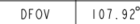
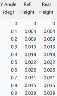
- Check if the parameters of the calibration file Lenspec.dat match the actual lens used. Verification method:

|
| ||||||||||||||||||
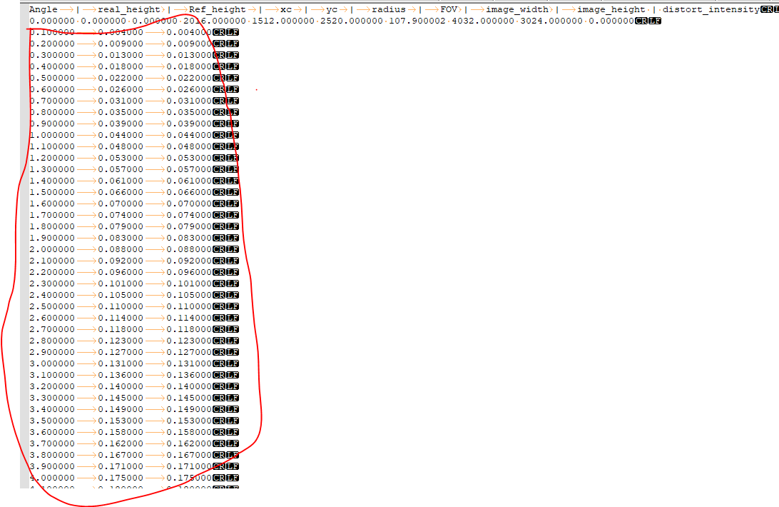
|
|

STEP2: If the above steps cannot resolve the issue
Provide the following information to the owner for analysis.
- Official manuals: Lens Spec file and Image Sensor Datasheet;
- Calibration related files: Lenspec.dat and CalibPoly_new.bin;
- Parameter values configured when problem occurs: MI_LDC_ChnDISAttr_t and MI_LDC_ChnLDCAttr_t;
- Logs when problem occurs: If problem appears before calling MI_LDC_StartChannel, then item b below is not needed
a. proc information: Execute
cat /proc/mi_modules/mi_ldc/mi_ldcXat runtime, X is devid; b. Algorithm log: After calling MI_LDC_StartChannel, executeecho calib_loglv chn_id 18 > /proc/mi_modules/mi_ldc/mi_ldcX, chn_id and X configured according to actual scenario; c. APP runtime log: Executeecho 7 > /proc/mi_modules/mi_ldc/debug_levelto capture.
4.6.1 "distor_intensity is too strong" Algorithm Log Appears
4.6.1.1 Phenomenon
When this situation occurs, it is generally accompanied by initial parameter configuration failure resulting in no stream, or dynamic parameter adjustment failure. Complete error log is as follows:
distor_intensity is too strong and cannot be suppored, please reduce !!!
ERR func: xxxxxx
4.6.1.2 Troubleshooting Direction
STEP1: Investigate possibility of excessive distortion correction intensity
The above log indicates that during distortion correction, the algorithm comprehensively judged multiple parameters and found that the current correction intensity is too strong to support. Therefore, prioritize reducing the s32DistortionRatio parameter value.
- Confirm if the s32DistortionRatio parameter is zero at this time. If zero, no need to proceed to step 2 for adjustment, proceed directly to STEP2;
- Gradually reduce the s32DistortionRatio parameter by step value 1 or 2 for configuration;
STEP2: Other troubleshooting methods
Follow Standardized Steps for troubleshooting.
4.6.2 "Undistortion ratio error" Algorithm Log Appears
4.6.2.1 Phenomenon
When this situation occurs, it is generally accompanied by initial parameter configuration failure resulting in no stream, or dynamic parameter adjustment failure. Complete error log is as follows:
Undistortion ratio error, please check binning ratio
[MI ERR]: xxxx
4.6.2.2 Troubleshooting Direction
STEP1: Investigate possibility of SensorDriver binning_mode parameter configuration error
The above log indicates that distortion ratio does not match actual sensor, need to check binning parameter configuration.
- Check if the binning_mode of the corresponding resolution in SensorDriver matches the datasheet. For example, if using 2x2 binning mode, the corresponding resolution's binning_mode should be configured as CUS_SEN_BINNING_2x2.
STEP2: Other troubleshooting methods
If the above STEP confirmation still has issues, follow Standardized Steps for troubleshooting.
4.6.3 "init flow error" Algorithm Log Appears
4.6.3.1 Phenomenon
When this situation occurs, it is generally accompanied by initial parameter configuration failure resulting in no stream, or dynamic parameter adjustment failure. Complete error log is as follows:
ERROR: init flow error, please call the get_boundary_function first !!!
[MI ERR]: xxxx
4.6.3.2 Troubleshooting Direction
STEP1: Follow unified method directly for troubleshooting
Follow Standardized Steps for troubleshooting.
4.6.4 "Crop initialization not centered per spec" Algorithm Log Appears
4.6.4.1 Phenomenon
When this situation occurs, it is generally accompanied by initial parameter configuration failure resulting in no stream. Complete error log is as follows:
[eis_algo_crop_size_check] Crop initialization not centered per spec. sensor height: x
[MI ERR]: xxxx
4.6.4.2 Troubleshooting Direction
STEP1: Investigate if SensorDriver corresponding resolution is centered crop
The above log indicates that based on SensorDriver parameters, the current image is not centered cropped during sensor crop. Need to check corresponding configuration.
- Check if the corresponding resolution is correctly centered cropped. If not, work with the manufacturer to adjust SensorDriver driver for centered cropping. If yes, proceed to next step;
- After confirming Sensor Crop is centered, check if the corresponding SensorDriver's w_x, h_y, ori_w, and ori_h are configured according to [IS User Guide] requirements.
STEP2: Other troubleshooting methods
If the above STEP confirmation still has issues, follow Standardized Steps STEP2 for troubleshooting.