SigmaStar SDMMC User Guide
REVISION HISTORY
| Revision No. | Description |
Date |
|---|---|---|
| 1.0 | 06/27/2023 | |
| 2.0 | 12/13/2023 |
1. INTRODUCTION
The MMC under Kernel adopts standard Linux framework, which allows it to use standard interface to drive various MMC devices (such as eMMC card, SD card, or SDIO device).
The MMC subsystem consists of card layer, core layer, and host layer. The Card layer registers the entire MMC Device as an MMC Block Device, which can support the data request of the upper layer; the Core layer implements the initialization process, as well as reading and writing, according to the MMC/SD/SDIO protocol. The host layer mobilizes the hardware and communicates the cmd or data request from the core layer with eMMC/SD/SDIO card through FCIE/SDIO Engine.
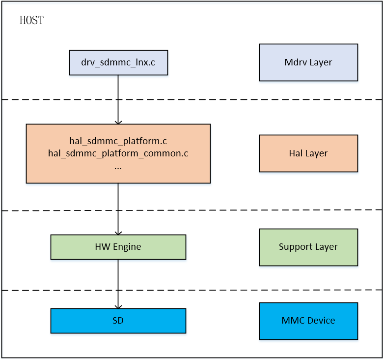
The overall framework of the SD host layer features three layers, namely the MDrv layer, the Hal layer, the Support layer, and the MMC device connected to the Support layer. The functions of each layer are as follows:
Mdrv Layer:
The Mdrv layer mainly completes the registration of the host, optimizes the description of mmc_host and mmc_host_ops structures, and adds information of the Host to the core layer. Encapsulation interfaces, such as debug_get_sdmmc_clock and set_sdmmc_driving_control, are also provided for the user layer to set or obtain the status of the Engine and SD card. In addition, the Mdrv layer also completes the MIE and hot swapping interrupt registration to ensure the normal reception and transmission of subsequent signals, as well as the detection of card insertion.
Hal Layer:
Registers are directly set in the Hal layer, which is closely related to the HW Engine. The Hal layer is mainly responsible for operating hal_sdmmc_v5.c file for the Host Engine. The sending and receiving of commands and data is implemented in this file. The hal_sdmmc_platform_common.c file determines which set of pad pins the Host Engine is connected to, and operates on them for pulling up and down. The hal_sdmmc_intr.c file is responsible for processing interrupt, while the hal_sdmmc_timer.c file is responsible for processing data related to time.
Support Layer:
This layer belongs to the layer of hardware support. The final implementation related to the driver requires hardware support.
MMC device:
MMC devices, such as SD/SDIO cards, are directly connected to the hardware support of the driver and are the final operation object of the driver.
2. KEYWORD
IP: The Host Engine which SD/SDIO cards are connecting to.
IP bank: The register address of Host Engine that drives SD/SDIO cards in access.
SDSC: SD card in the format of Secure Digital Standard Capacity, with a capacity of up to 2 GB.
SDHC: SD card in the format of Secure Digital High Capacity, with capacities from 2 GB up to 32 GB.
SDXC: SD card in the format of Secure Digital eXtended Capacity, with capacities larger than 32 GB.
3. FUNCTION DESCRIPTION
| Package | SD Card | Bus Bandwidth | Clock Range | Speed Supported by SD3.0 | Speed Supported by SD2.0 | IP bank | Product |
|---|---|---|---|---|---|---|---|
| BGA | SD0 Card | 1, 4 | 300k ~ 200M | SDR50, SDR104, DDR50 | Default Speed, High Speed | 0x1413 | souffle |
| BGA | SD1 Card | 1, 4 | 300k ~ 100M | SDR50 | Default Speed, High Speed | 0x1416 | souffle |
| QFN | SD0 Card | 1, 4 | 300k ~ 200M | SDR50, SDR104, DDR50 | Default Speed, High Speed | 0x1413 | souffle |
| BGA | SD0 Card | 1, 4 | 300k ~ 48M | - | Default Speed, High Speed | 0x1413 (non-pm) | iford |
| BGA | WIFI Card | 1, 4 | 300k ~ 48M | - | Default Speed, High Speed | 0x42 (pm) | iford |
Note: The Souffle BGA-package board has 2 SD card slots, among which SD0 supports a maximum rate of 200M and SD1 only supports a maximum rate of 100M. The QFN-package board has only one SD card slot, which supports a maximum rate of 200M.
Set Bus Bandwidth:
SD supports two bus bandwidth configurations: 1 (1-bit mode) and 4 (4-bit mode). To set the bus bandwidth to 1-bit mode for SDIO card, you may adjust the sdio-use-1bit parameter in the device tree.
Set Clock Frequency:
Souffle: SD0 Card supports clock frequency configuration ranging from 300KHz to 200MHz, while SD1 Card supports clock frequency configuration ranging from 300KHz to 100MHz. You may configure the largest clock frequency by modifying the max-frequency parameter in the device tree. The final clock frequency will be the largest frequency supported by the current bus speed.
iFord: SD0 Card/WIFI Card supports clock frequency configuration ranging from 300KHz to 48MHz. You may configure the largest clock frequency by modifying the max-frequency parameter in the device tree. The final clock frequency will be the largest frequency supported by the current bus speed.
The currently supported gears are listed below:
| iford clock gears | non-pm | pm |
|---|---|---|
| 0 | 48000000 | 50000000 |
| 1 | 43200000 | 33400000 |
| 2 | 40000000 | 12000000 |
| 3 | 36000000 | 3000000 |
| 4 | 32000000 | - |
| 5 | 20000000 | - |
| 6 | 12000000 | - |
| 7 | 3000000 | - |
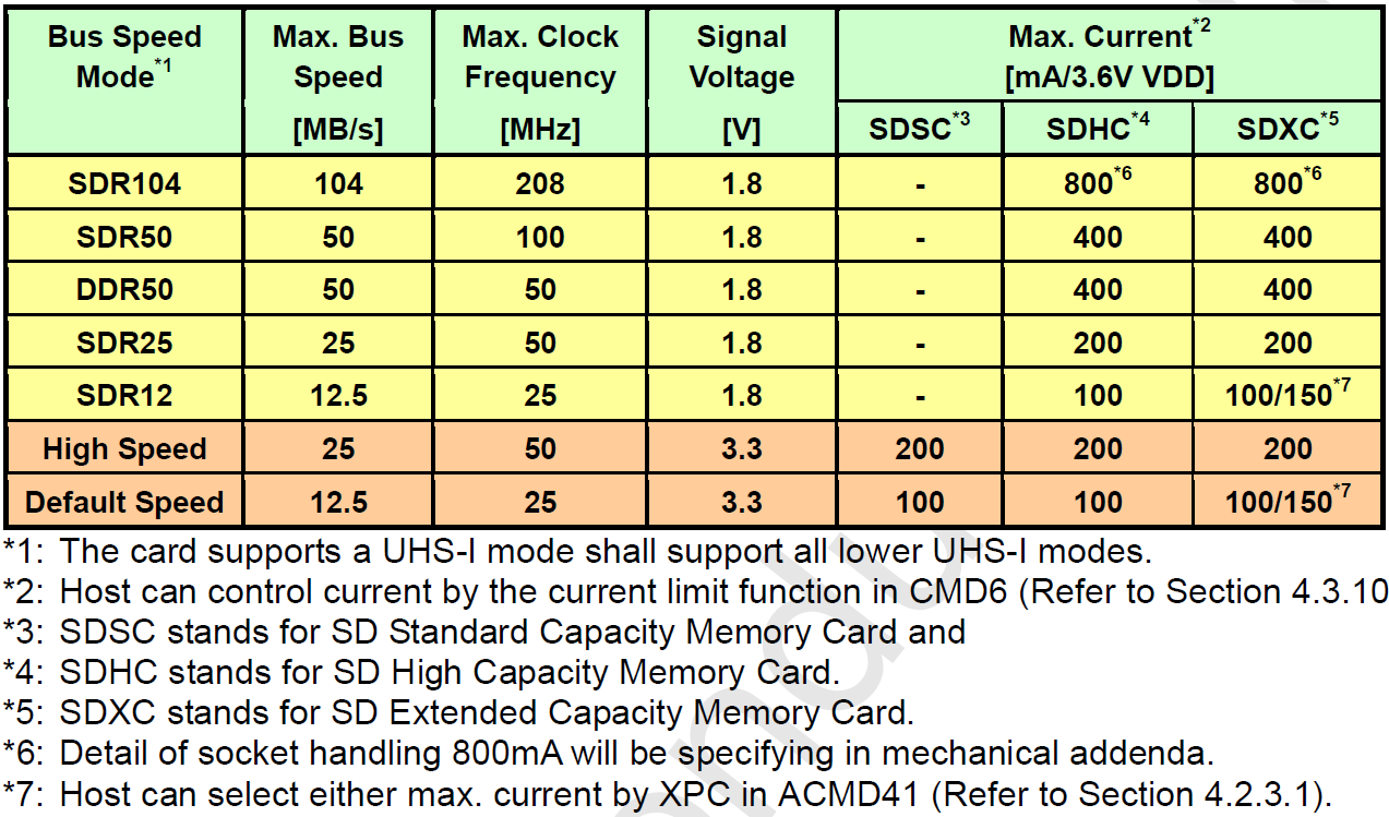
The configuration of different bus bandwidths and clock frequencies will affect the speed of data transmission. SD3.0 supports SDR50, SDR104, and DDR50 speed. To use it, you can configure sd-uhs-sdr50/sd-uhs-sdr104/sd-uhs-ddr50 in the corresponding slot in the device tree.
Speed Mode:
-
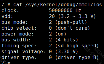
Check the SD card speed mode:
cat /sys/kernel/debug/mmc1/ios
-
Set the SD card speed mode:
The SD card speed mode can be configured directly in the dtsi file for Souffle and later products.
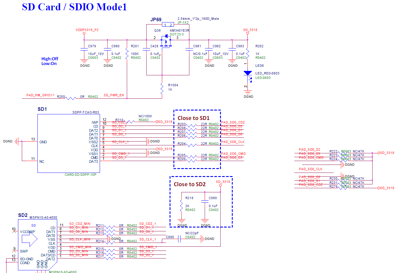
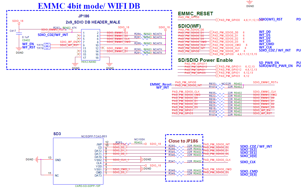
4. HARDWARE CONNECTION
5. Uboot USER GUIDE
5.1. uboot config Setting
1. make menuconfig
2. # SigmaStar drivers -->
3. #    <*> SigmaStar mmc host
Under boot, SDMMC driver is located in drivers/sstar/mmc_host/ directory. To compile the file, you will need to enable SSTAR_MMC_HOST compile function by entering the command above.
5.2. Dts Parameter Configuration
You may set the basic parameters of driver in the host layer by configuring sstar_mmc0 in dtsi. The parameters in dtsi are set out below:
sstar_mmc0: sstar_mmc0 {
            compatible = "sstar-mmc";

            bus-width = <4>;
            max-frequency = <48000000>;
            cap-mmc-highspeed = <1>;
            ip-order = <0>;
            pad-orders = <0>;
            pwr-on-delay = <10>;
            pwr-off-delay = <50>;
            fack-cdz = <0>;
            rev-cdz = <0>;
            pwr-pad = <PAD_SD0_GPIO0>;
            cdz-pad = <PAD_SD0_CDZ>;
            clk-driving  = <1>; //0~7
            cmd-driving  = <1>; //0~7
            data-driving = <1>; //0~7
            en-clk-phase = <0>; //0/1
            rx-clk-phase = <0>; //0-3
            tx-clk-phase = <0>; //0-3
            status = "okay";
        };
The description of parameters are set out below:
| Parameter | Description | Note |
|---|---|---|
| bus-width | Configure the bus width of card slot. | 4 – 4bit mode |
| max-frequency | Configure the maximum clock frequency supported by the corresponding card slot. | |
| ip-order | Configure the IP number of the corresponding card slot. | |
| pad-order | Designate the pad to be connected to the card. | |
| pwr-on-delay | Configure the power-on delay time of each card slot in the unit of ms. | SDIO device normally needs to have its delay time configured so as to facilitate SDIO device loading firmware and reaching ready status. Please follow the suggestion of SDIO device manufacturers for the exact delay time needed. |
| pwr-off-delay | Configure the power-off delay time of each card slot in the unit of ms. | |
| fake-cdz | Configure whether card detection should be ignored. Setting this parameter to 1 indicates that card insertion is recognized by default. | We suggest that you configure the card detection to 1 for certain SDIO devices that are fixed to the board. |
| rev-cdz | This parameter can be configured to reverse the card detection condition for the current board. | |
| pwr-pad | Configure the power pin for the corresponding card slot. | |
| cdz-pad | Configure the CDZ pin for the corresponding card slot. | |
| clk-driving | Configure the driving capacity of clock pad pin for the corresponding card slot. | Value range: 0 ~ 7 (iford: 0 ~ 3). |
| cmd-driving | Configure the driving capacity of command pad pin for the corresponding card slot. | Value range: 0 ~ 7 (iford: 0 ~ 3). |
| data-driving | Configure the driving capacity of data[3:0] pad pin for the corresponding card slot. | value range: 0 ~ 7 (iford: 0 ~ 3). |
| en-clk_phase | Configure whether clock phase tuning should be enabled for the corresponding card slot. | |
| rx-clk_phase | Configure the phase of clock tx for the corresponding card slot. This parameter is effective only when en-clk_phase is set to 1. | Value range: 0 ~ 3. |
| tx-clk_phase | Configure the phase of clock rx for the corresponding card slot. This parameter is effective only when en-clk_phase is set to 1. | Value range: 0 ~ 3. |
5.3. Uboot cmd Parameter Description
(1) fatls
Format:
fatls <interface> [<dev[:part]>] [directory]
Description: Read the content of all files under a certain directory of the n~th partition of the n~th device.
interface: SD card and eMMC card both belong to MMC device.
dev: Device number according to IP numbering. Default is 0.
part: Corresponds to the partition number under mmc part command.
directory: Directory. Absolute path should be used.
Example: Print out the content of the root directory of the first partition of SD.
fatls mmc 0:1 /
(2) fatload
Format:
fatload <interface> <dev<:part>> <addr> <filename> <bytes <pos>>
Description: Load a specific size of data from a certain file from the n~th partition of the n~th device of a certain interface to the DDR of a specified address.
addr: Target memory address, DDR address, real physical address should be used.
filename: The name of the file to be loaded. Absolute path and filename should be used.
bytes: The size of data to be loaded in the unit of byte and hexadecimal numbering. 0 indicates the entire file.
pos: The offset amount of target file. If, for example, the target file data reads "123456" and pos is set to 1, the data will be loaded starting from the position of 1.
Example: Load 512 bytes from the file demo.sh under the root directory of the first partition of the SD card to 0x21000000 of DDR.
fatload mmc 0:1 0x21000000 /demo.sh 0x200
(3) fatwrite
Format:
fatwrite <interface> <dev<:part>> <addr> <filename> <bytes>
Description: Load a specific size <bytes> of data from the DDR of a designated address to a certain file in the n~th partition of the n~th device of a certain interface.
addr: Source memory address, DDR address. Real physical address should be used.
filename: The filename to be written. Absolute path and filename should be used.
bytes: The size of data to be written in the unit of byte and hexadecimal numbering.
Example: Read 512 bytes from 0x21000000 of DDR to the file demo.sh under the root directory of the first partition of the SD card.
fatwrite mmc 0:1 0x21000000 /demo.sh 0x200
(4) fatinfo
Format:
fatinfo <interface> <dev<:part>>
Description: Show data of the n~th partition of the n~th device under a certain interface.
(5) fatsize
Format:
fatsize <interface> <dev<:part>> <filename>
Description: Find a certain file in the n~th partition of the n~th device under a certain interface and then calculate its size.
5.4. Uboot cmd User Guide
(1) fdisk
Fdisk is used to manage linux disk, such as creating partitions and formatting.
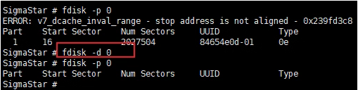
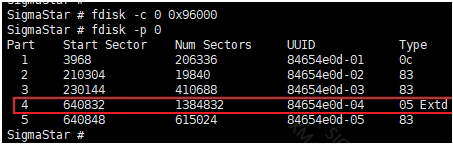
fdisk -p to show partition information

(2) fdisk -d 0: Delete all partitions of device 0.
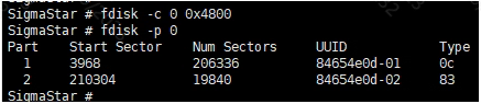
(3) fdisk -c 0 0x32000: Create partition 1 and designate its size as 0x32000 blocks.

(4) fdisk -c 0 0x4800: Create partition 2 and designate its size as 0x4800 block.
(5) fdisk -c 0 0x64000: Create partition 3 and designate its size as 0x64000 blocks.

(6) fdisk -c 0 0x96000: Create partition 5 and designate its size as 0x96000 blocks. Here, partition 4 is the extended partition mbr, so we need to skip it.
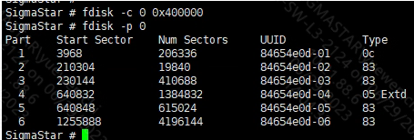
(7) fdisk -c 0 0x400000: Create partition 6 and designate its size as 0x400000 blocks.
6. Kernel User Guide
6.1. Kernel Config Configuration
1. Related Driver Module
The Card layer (mmc_block.ko) and the Core layer (mmc_host.ko) use standard linux code. The Host layer (kdrv_emmc.ko) is maintained by SigmaStar. You can choose to compile them into the kernel or compile them as ko files in menuconfig.
2. Driver Modules Corresponding to enable
1. make menuconfig
2. # Device Drivers -->
3. #    <*> MMC/SD/SDIO card support -->                   (mmc_core.ko)
4. #        <*> MMC block device driver                    (mmc_block.ko)
5. #    [*] SStar SoC platform drivers -->
6. #        <*> SStar SD/MMC Card Interface Support        (kdrv_sdmmc.ko)
7. #        [ ]     Support SD30
8. #        [ ]     Support EMMC50
9. #        [*]     Support SDMMC Command
10.#        [*]       Support SDMMC UT verify
6.2. Dts Parameter Configuration
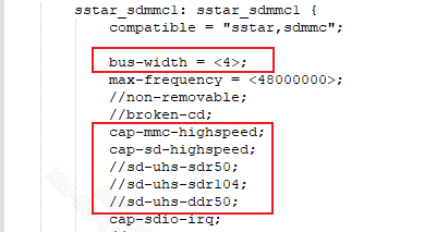
You may set the basic parameters of driver in the Host layer by configuring sstar_sdmmc1 in dtsi. The parameters in dtsi are set out below:
sstar_sdmmc1: sstar_sdmmc1 {
            compatible = "sstar,sdmmc";

            bus-width = <4>;
            max-frequency = <48000000>;
            //non-removable;
            //broken-cd;
            cap-mmc-highspeed;
            cap-sd-highspeed;
            //sd-uhs-sdr50;
            //sd-uhs-sdr104;
            //sd-uhs-ddr50;
            cap-sdio-irq;
            //no-sdio;
            //no-sd;
            no-mmc;
            reg = <0x1F282600 0x200>;
            pll-reg = <0x1F283400 0x200>;
            cifd-reg = <0x1F282800 0x200>;
            pwr-save-reg = <0x1F282A00 0x200>;
            ip-order = /bits/ 8 <0>;
            pad-order = /bits/ 8 <0>;
            trans-mode = /bits/ 8 <1>;
            support-cmd23 = /bits/ 8 <1>;
            fake-cdz = <0>;
            rev-cdz = /bits/ 8 <0>;
            cdz-pad = <PAD_SD0_CDZ>;
            pwr-pad = <PAD_PM_GPIO11>;
            pwr-on-delay = <1>;
            pwr-off-delay = <30>;
            sdio-use-1bit = /bits/ 8 <0>;
            clk-driving = <2>;
            cmd-driving = <2>;
            data-driving = <2>;
            en-clk-phase = /bits/ 8 <0>; //0/1
            rx-clk-phase = <0>; //0-3
            tx-clk-phase = <0>; //0-3
            en-eight-phase = /bits/ 8 <0>; //0/1
            rx-eight-phase = /bits/ 8 <0>; //0/1
            tx-eight-phase = /bits/ 8 <0>; //0/1
            interrupts = <GIC_SPI INT_IRQ_SD IRQ_TYPE_LEVEL_HIGH>,
                         <GIC_SPI INT_FIQ_SD_CDZ_0 IRQ_TYPE_LEVEL_HIGH>;
            interrupt-names = "mie0_irq", "cdz_slot0_irq";
            clocks = <&CLK_sd>;
            clock-names = "clk_sdmmc0";
            status = "ok";
    };
As shown by the figure above, the explanation of SD/SDIO device tree configuration nodes is set out below:
| Parameter | Description | Note |
|---|---|---|
| bus-width | Configure the buswidth of the corresponding card slot | 4 - 4bit mode |
| max-frequency | Configure the maximum clock frequency supported by the corresponding card slot | The maximum clock frequency supported by iford is 48MHz |
| non-removable | Configure whether the device cannot be removed. Set to 1 to indicate that the device is non-removable by default. | eMMC/SDIO devices are generally set as non-removable |
| broken-cd | Configure whether to use cdz interrupt | |
| cap-mmc-highspeed | Configure whether the device supports MMC highspeed bus speed mode | MMC highspeed mode support is enabled by default |
| cap-sd-highspeed | Configure whether the device supports SD highspeed bus speed mode | SD highspeed mode support is enabled by default |
| sd-uhs-sdr50 | Configure whether to enable sdr50 bus rate mode | Not used in iford |
| sd-uhs-sdr104 | Configure whether to enable sdr104 bus speed mode | Not used in iford |
| sd-uhs-ddr50 | Configure whether to enable DDR bus speed mode | Temporarily not in use |
| cap-sdio-irq | Configure whether to enable SDIO interrupt mode | For use by SDIO device |
| no-mmc | Configure whether the device supports eMMC protocol or not | SD/SDIO device does not support eMMC protocol |
| reg | Configure SD/SDIO Host Engine Bank address | Use according to the 'Function Description' |
| pll-reg | Configure SD/SDIO Host Engine PLL Bank address | Not used in iford |
| cifd-reg | Configure SD/SDIO Host Engine CIFD Bank address | SD/SDIO Host supports adma/dma/cifd data transmission mode. Among them, adma is recommended. |
| pwr-save-reg | Configure SD/SDIO Host Engine PSM Bank address | SD/SDIO Host supports IP-level power failure protection function |
| ip-order | Configure the IP number of the corresponding card slot | Currently iford supports 0, 1 |
| pad-order | Configure the padmux mode number of the corresponding card slot | Configure padmux mode according to actual hardware |
| trans-mode | Configure the data transmission mode of the corresponding card slot | Not used in iford; adma is used by default |
| fake-cdz | Configure whether the corresponding card slot should ignore Card Detection | This is recommended for SDIO device |
| rev-cdz | Configure CDZ detection direction | |
| pwr-on-delay | Configure the power-on delay time of the corresponding card slot | |
| pwr-off-delay | Configure the power-off delay time of the corresponding card slot | Normally, delay time should be configured for SDIO device. By doing so, SDIO device will load firmware and get to ready status more conveniently. Please follow the suggestion of SDIO device manufacturers for the exact delay time needed. |
| sdio-use-1bit | Configure the corresponding card slot buswidth to 1bit mode | Can be set for SD/SDIO device |
| support-cmd23 | Configure whether to support the preset transmission block number function | Used for eMMC device |
| clk-driving | Configure the driving of the clock line corresponding to the card slot | Value range: 0 ~ 7 (iford: 0 ~ 3) |
| cmd-driving | Configure the driving of the cmd line corresponding to the card slot | Value range: 0 ~ 7 (iford: 0 ~ 3) |
| data-driving | Configure the driving of the data line corresponding to the card slot | Value range: 0 ~ 7 (iford: 0 ~ 3) |
| en-clk-phase | Configure whether to enable clock phase tuning for the corresponding card slot | 0 - Disabled / 1 - Enabled |
| rx-clk-phase | Configure the clock rx phase of the corresponding card slot | Value range: 0-3, this parameter takes effect when en-clk-phase is set to 1. |
| tx-clk-phase | Configure the clock tx phase of the corresponding card slot | Value range: 0-3, this parameter takes effect when en-clk-phase is set to 1. |
| en-eight-phase | Configure whether to enable clock 8 phase tuning for the corresponding card slot | 0 - Disabled / 1 - Enabled; not used in iford |
| rx-eight-phase | Configure the clock rx phase of the corresponding card slot | Value range: 0-5, this parameter takes effect whenen-eight-phase is set to 1. |
| tx-eight-phase | Configure the clock tx phase of the corresponding card slot | Value range: 0-5, this parameter takes effect whenen-eight-phase is set to 1. |
| interrupts | Configure the interrupt information | Just keep the default value |
| interrupt-names | Configure the interrupt names | Used in combination with interrupts |
| clocks | Configure the clock source of eMMC Host Engine | Just keep the default value |
| clock-names | Configure the name of the clock source | Used in combination with clocks |
In order to facilitate the unified management of padmux, sdmmc driver also supports using padmux.dtsi to configure the pad group to be used. When padmux.dtsi has PUSE about SDMMC, the driver will use this method to configure padmux first. This method can intuitively find out whether there is a pad conflict with other modules. Examples are as follows:
1.    padmux {
2.        compatible = "sstar-padmux";
3.        schematic =
4.            //SDMMC0
5.            <PAD_SD0_D1     PINMUX_FOR_SD0_MODE_1        MDRV_PUSE_SDIO0_D1>,
6.            <PAD_SD0_D0     PINMUX_FOR_SD0_MODE_1        MDRV_PUSE_SDIO0_D0>,
7.            <PAD_SD0_CLK    PINMUX_FOR_SD0_MODE_1        MDRV_PUSE_SDIO0_CLK>,
8.            <PAD_SD0_CMD    PINMUX_FOR_SD0_MODE_1        MDRV_PUSE_SDIO0_CMD>,
9.            <PAD_SD0_D3     PINMUX_FOR_SD0_MODE_1        MDRV_PUSE_SDIO0_D3>,
10.           <PAD_SD0_D2     PINMUX_FOR_SD0_MODE_1        MDRV_PUSE_SDIO0_D2>,
11.           <PAD_SD0_GPIO0  PINMUX_FOR_GPIO_MODE         MDRV_PUSE_SDIO0_PWR>,
12.           <PAD_SD0_CDZ    PINMUX_FOR_SD0_CDZ_MODE_1    MDRV_PUSE_SDIO0_CDZ>;
13.    };
Depending on the actual use case, you may replace the PAD name in the first column and the second group of pad modes corresponding to the pad.
6.3. Sample code
N/A.
6.4. Module User Guide
After the Linux system starts, the SD/SDIO driver is loaded normally and the SD/SDIO Card is recognized, the corresponding block device node /dev/mmcblk* will be created. Use fdisk, mkfs, mount and dd tools to apply for partitions on MMC devices, format partitions, mount partitions, and read and write the mounted partitions.
In addition, the driver also provides sysfs for debugging. After entering the /sys/devices/soc0/soc/{reg}.sstar_sdmmc1 directory, you can perform the operation intended.
1.  cd /sys/devices/soc0/soc/{reg}.sstar_sdmmc1
2.
3.  # View the SD/SDIO Host clock frequency
4.  cat debug_get_sdmmc_clock
5.
6.  # Check the last communication status between SD/SDIO Host and Device
7.  cat debug_get_sdmmc_status
8.
9.  # Set the SD/SDIO bus width
10. echo [buswidth] > sdmmc_bus_width_set
11. #[buswidth] -2: 4bit buswidth
12. #           -0: 1bit buswidth
13. #           -others: invalid
14.
15. # Set the SD/SDIO clock and Timing mode
16. echo [clk_freq] > sdmmc_clk_timing_set
17. #[clk_freq] Unit: Hz
18. # -[0,12MHz): set clock only
19. # -[12MHz, 26MHz]: set timing to MMC_TIMING_LEGACY and set clock
20. # -(26MHz, 50MHz): set timing to MMC_TIMING_MMC_HS and set clock
21.
22. # Set the SD/SDIO Host to use interrupt or polling mode
23. echo [intr_en] > sdmmc_inter_polling_set
24. #[intr_en] -0: polling mode
25. #          -1: interrupt mode
26. # Tips: If the SD/SDIO Host is already working in polling mode, you cannot switch to interrupt mode.
27.
28. # Set the SD/SDIO pin driving strength
29. echo [slotIndex] [signalLine] [drvLevel] > set_sdmmc_driving_control
30. echo [slotIndex]  [drvLevel] > set_sdmmc_driving_control
31. echo [signalLine] [drvLevel] > set_sdmmc_driving_control
32. echo [drvLevel] > set_sdmmc_driving_control
33. #[slotIndex]: 0-1
34. #[signalLine]: "clk"/"cmd"/"data"/"all"
35. #[drvLevel]: 0-7 (iford support 0-3)
6.5 SD Driving Capability Configuration
6.5.1 Driving Capability Configured by sysfs
SD driver provides sysfs control pin driving capability, please refer to the following instruction:
1. cd /sys/devices/soc0/soc/<reg>:sstar_sdmmc[i]
2. # <reg> - Generate Reg value based on the actual configuration information of DTSI
3. # [i]   - Generate index value based on the actual configuration information of DTSI
4. echo [slotNo] <signal> [level] > set_sdmmc_driving_control
5. # Set driving capability as [level] for the signal line <signal> of [slotNo].
6. # [slotNo] - Select the slot to be operated.
7. # <signal> - You may choose to set clk, cmd, data, all, or null (equal to all).
8. # [level]  - driving capability level. Value range: 0 ~ 4.
Set the driving capability of all signal pins of sd to 2
1. cd /sys/devices/soc0/soc/1f282600.sstar_sdmmc1
2. echo 0 all 2 > set_sdmmc_driving_control
6.5.2 Driving Capability Configured by dts
SD driver supports configuring the driving capabilities of clk, cmd and data signal lines from dts. The configuration is as follows:
1. sstar_sdmmc0: sstar_sdmmc0 {
2.     compatible = "sstar,sdmmc";
3.     bus-width = <4>;
4.     no-sdio;
5.     no-sd;
6.     …
7.     clk-driving = <2>;
8.     cmd-driving = <2>;
9.     data-driving = <2>;
10.    …
11. }

1. sstar_sdmmc1: sstar_sdmmc1 {
2.     compatible = "sstar,sdmmc";
3.     bus-width = <4>;
4.     no-mmc;
5.     …
6.     clk-driving = <1>;
7.     cmd-driving = <1>;
8.     data-driving = <1>;
9.    …
10. }
As shown above, these three attribute parameters configure the driving capabilities of the clk line, cmd line and four data lines, respectively.
7. API Reference
N/A.
8. Debug & FAQ
SD card status register description:
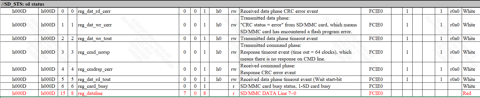
You can find the corresponding SD card status according to the information (e.g. 0xXXXX) in the error log of the driver to determine what is wrong with the current card.
The problems that the SD card may encounter under actual circumstances can be categorized into the following types:
Card identification failed
If card identification failed, you need to determine whether the problem is response failed to be obtained or the transmission signal is bad, which indicates a CRC problem. The problem can be identified through the log printed by the driver. The specific difference and the debugging method are as follows:
-
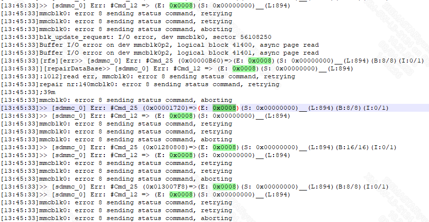
SD card failed to send a Response to the command
Phenomenon: A log (e.g. 0x0008) is printed by the driver.
Debug method: First, check voltage and clock, and then capture the waveform to see if there is a command sent by the host. If there is no problem with the first two, then check whether the card answers the response. If there is no response, check the device status.
Related log:
-
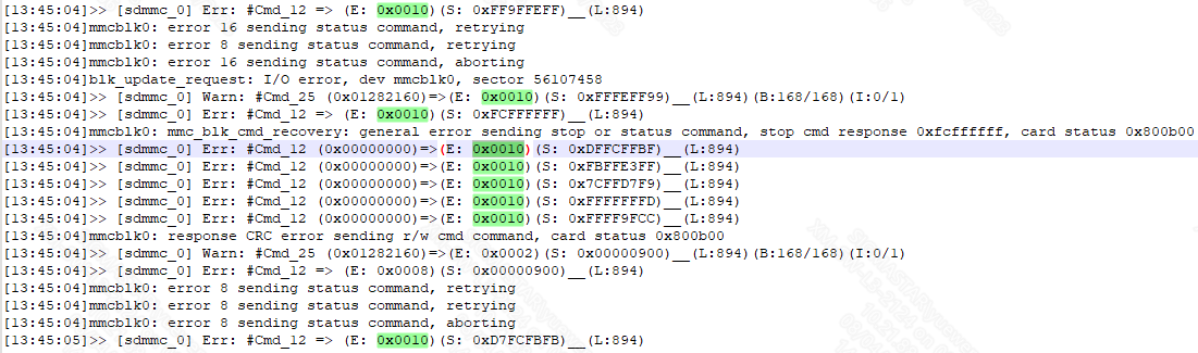
The response to the command has a CRC problem
Phenomenon: A log (e.g. 0x0010) is printed by the driver.
Debug method: If there is a CRC problem, you need to first rule out hardware problems, such as: whether the device is properly connected, whether external interference exists, etc. After that, try to change the driving level in dts, if there are still problems, you need to consider adjusting the clock phase.
Related log:
Read/Write failed
If you encounter problems during normal reading and writing process, you need to determine whether it is a reading and writing timeout problem, or the problem is with CRC due to bad signals. The problem can be identified by looking up the log. The timeout problem will show timeout. The debugging method is as follows:
-
Reading and writing timeout
Phenomenon: The word timeout shows up in the error log printed by the driver.
Debug method: First, you need to determine whether the current clock frequency and bus width are the expected configuration values. Second, you can try to increase the timeout time in the driver. If there is still a timeout problem, you need to capture the waveform for further analysis.
The read and write timeout time is set in the hal_card_platform_config.h file in the corresponding chip directory of the driver:
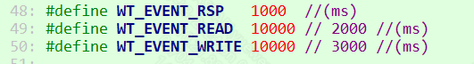
-
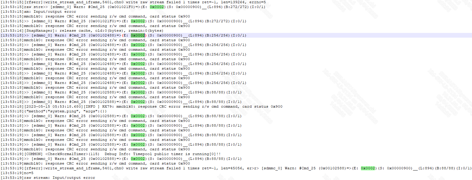
CRC problem related to reading and writing
Phenomenon: A log (e.g. 0x0001 or 0x0002) is printed by the driver.
Debug method: Please refer to the previous section for the debug method. In addition, if speed is not of primary concern, you may consider lowering the frequency or reducing the bus width.
Related log:
Card reading and writing speed is slow
First check whether the card clock frequency and bus width are normal. In addition, you can test and compare the read and write speeds of different types of cards.
Note: SD card reading and writing is affected by multiple factors such as the transmission time of commands and their responses, card busy time, and stop command time. The actual reading and writing speed is lower than its theoretical speed. The read and write speed test should test the read and write bandwidth of the application layer, that is, transfer a large file for testing.