USB Host/Device User Guide
REVISION HISTORY
| Revision No. | Description |
Date |
|---|---|---|
| 1.0 | 07/07/2023 | |
| 1.1 | 08/07/2024 | |
| 1.2 | 11/20/2025 | |
| 1.3 | 03/16/2026 |
1. Overview
USB(Universal Serial Bus) is a widely used interface standard, mainly used to connect computers with external devices, achieve data transmission and device power supply.
The USB specification of the IFORD platform includes one USB2.0 Host and one Device. Since the Host and Device share the same UTMI, they cannot be used at the same time. The hardware does not support USB3.0.
2. Keyword Description
-
Device
External hardware, such as USB drives, keyboards, mobile devices, etc., that connects computers or other devices through a USB interface to achieve data transfer, power supply, or expansion functions.
-
Host
USB Host is the main control terminal that controls the USB bus and manages connected devices (such as computers and mobile phones). It is responsible for power supply, data transmission coordination, and driver loading, enabling external devices (such as USB drives and mice) to work properly.
-
EHCI
The Enhanced Host Controller Interface specification defines a register-level interface to the Universal Serial Bus (USB) 2.0 host controller.
-
UTMI
The USB2.0 Transceiver Macrocell Interface protocol, defined from the perspective of USB2.0 signal characteristics, is divided into 8-bit and 16-bit data interface.
3. Function Description
-
The USB HOST supports various devices such as keyboards, mice, USB flash drives, USB network cards, USB cameras, USB headsets, etc., and also supports USB hubs to expand the number of USB interfaces.
-
The USB device can be configured as a USB camera, USB audio capture and playback, RNDIS, and other devices.
3.1. IFORD
-
Supports 2 USB 2.0 ports
-
Each USB 2.0 port supports host mode and device mode
-
USB 2.0 Device EP resources
EP0 EP1 EP2 EP3 EP4 EP5 EP6 64 8192 1024 64 512 512 64
4. Usage of USB in Uboot
4.1 Using USB2.0 Host Driver
4.1.1 USB 2.0 Host Menuconfig
    -> Device Drivers
        -> [*] USB support --->
            -> <*>   Support for Host-side USB
                -> [*] Enable driver model for USB Gadget
                -> [*] EHCI HCD (USB 2.0) support

    -> [*] SigmaStar drivers  --->
        -> -*-   SigmaStar USB2.0 Host Controller
        -> [*] Sgs USB Reset Control
4.2. Using the USB 2.0 Device Driver
4.2.1. USB 2.0 Device menuconfig Configuration
    -> Device Drivers
        -> [*] USB support --->
            -> [*] Enable driver model for USB Gadget
            -> [*] USB Gadget Support --->

    -> [*] SigmaStar drivers  --->
        -> [*] SigmaStar USB 2.0 Device Controller
        -> [*] Sgs USB Reset Control
4.3. ufu usage
To enable CMD_SSTAR_UFU in uboot config, if you need to compile an upgraded uboot with empty chips, you also need to additionally enable CONFIG_SSTAR_AUTOBOOT_RUN_UFU_ALWAYS
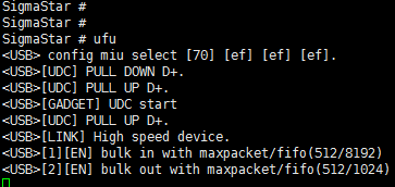
Usage:Enter ufu under uboot to enter ufu upgrade mode and wait for the PC tool to start the upgrade
4.4. usbstar usage
The uboot configuration needs to enable CMD_SSTAR_SUSBSTAR
Usage:Execute ./image/makefiletools/script/make_usb_upgrade_sigmastar.sh in project directory,put the generated bin into a Fat32 USB flash drive and connect it to the USB HOST port, Enter usbstar under uboot to start upgrading
5. Usage of USB in Kernel
5.1 Using USB2.0 Host Driver
5.1.1 USB 2.0 Host Menuconfig
-> Device Drivers

    -> [M] USB support --->

        -> <M> EHCI HCD (USB 2.0) support

            -> [*] Root Hub Transaction Translators

            -> [*] Improved Transaction Translator scheduling
Please select the above options to compile the USB 2.0 Host driver: usb-common.ko usbcore.ko ehci-hcd.ko.
-> Device Drivers

    -> [*] SStar SoC platform drivers --->

         -> <*>   SStar USB2 PHY Driver
Please select the above options to compile sstar-usb2-phy.ko.ko.
Load ko in the following order:
    #USB2.0 host normal ko
    usb-common.ko
    usbcore.ko
    sstar-usb2-phy.ko
    ehci-hcd.ko
5.1.2 DTS Node Configuration
usb2phy1_utmi: utmi@0x1f284200 {
    compatible="syscon";
    reg = <0x1f284200 0x200>;
    reg-io-width = <2>;
};

usb2phy1_bc: bc@0x1f284400 {
    compatible="syscon";
    reg = <0x1f284400 0x200>;
    reg-io-width = <2>;
};

usb2phy1_usbc: usbc@0x1f284600 {
    compatible="syscon";
    reg = <0x1f284600 0x200>;
    reg-io-width = <2>;
};

usb2phy1_uhc: uhc@0x1f284800 {
    compatible="syscon";
    reg = <0x1f284800 0x200>;
    reg-io-width = <2>;
};

sstar_u2phy: sstar-usb2-phy {
    compatible = "sstar,u2phy";
    #address-cells = <1>;
    #size-cells = <1>;
    ranges;
    status = "ok";

    sstar_u2phy1: u2phy1 {
        syscon-utmi = <&usb2phy1_utmi>;
        syscon-uhc = <&usb2phy1_uhc>;
        syscon-usbc = <&usb2phy1_usbc>;
        syscon-bc = <&usb2phy1_bc>;
        //utmi_dp_dm_swap = <0>;
        #phy-cells = <0>;
        status = "ok";
    };
};
sstar-ehci-1 {
    compatible = "sstar-ehci-1";
    reg-names = "ehc_base";
    reg = <0x1f284800 0x200>;
    syscon-utmi = <&usb2phy1_utmi>;
    syscon-usbc = <&usb2phy1_usbc>;
    syscon-bc = <&usb2phy1_bc>;
    //clocks = <&CLK_upll_480m>;
    interrupts = <GIC_SPI INT_IRQ_UHC IRQ_TYPE_LEVEL_HIGH>;
    phys = <&sstar_u2phy1>;
    phy-names = "usb";
    support_high_2g_access_patch;
    //power-enable-pad = <PAD_GPIO8>;
    status = "ok";
};
5.1.3 DTS Parameter
5.1.3.1 EHCI DTS Parameter
| Attribute | Description | Note |
|---|---|---|
| compatible | Used to match the driver for driver registration | Modification not allowed |
| syscon-utmi | Syscon node for specifying UTMI bank, to facilitate the use of regmap to access registers | Modification not required |
| syscon-uhc | Syscon node for specifying EHCI bank, to facilitate the use of regmap to access registers. Same as the reg attribute. | Modification not required |
| syscon-usbc | Syscon node for specifying USBC bank, to facilitate the use of regmap to access registers | Modification not required |
| syscon-bc | Syscon node for specifying BC bank, to facilitate the use of regmap to access registers | Modification not required |
| interrupts | Used to specify the interrupt and trigger mode of EHCI | Modification not allowed |
| phys | Used to specify the phy list used by EHCI | Modification not required |
| phy-names | Used to specify the name of the phy list supported by the phys attribute, corresponding to the phy list | Modification not required |
| clocks | Used to enable EHCI clock | Modification not allowed |
| status | Used to select whether to enable the driver | Can be modified where necessary |
5.1.3.2 Phy DTS Parameter
| Attribute | Description | Note |
|---|---|---|
| compatible | Used to match the driver for driver registration | Modification not allowed |
| #address-cells | Used to specify the word length (32-bit) occupied by the address information of the reg attribute of the child node | Modification not allowed |
| #size-cells | Used to specify the word length (32-bit) occupied by the address range information of the reg attribute of the child node | Modification not allowed |
| ranges | Used to indicate that the child nodes inherit #address-cells and #size-cells attributes | Modification not required |
| status | Used to select whether to enable the driver | Can be modified where necessary |
5.1.3.3 Phy Child Node DTS Parameter
| Attribute | Description | Note |
|---|---|---|
| syscon-utmi | Syscon node for specifying UTMI bank, to facilitate the use of regmap to access registers | Modification not required |
| syscon-uhc | Syscon node for specifying EHCI bank, to facilitate the use of regmap to access registers. Same as the reg attribute. | Modification not required |
| syscon-usbc | Syscon node for specifying USBC bank, to facilitate the use of regmap to access registers | Modification not required |
| syscon-bc | Syscon node for specifying BC bank, to facilitate the use of regmap to access registers | Modification not required |
| syscon-utmi2 | Syscon node for specifying UTMI2 bank, to facilitate the use of regmap to access registers | Modification not required |
| status | Used to select whether to enable the driver | Can be modified where necessary |
5.2 Using USB2.0 Device Driver
5.2.1 USB 2.0 Device Menuconfig
-> Device Drivers

    ->[*] USB support --->

        -><*> USB Gadget Support --->

            -> USB Peripheral Controller --->

                -> <M> Sstar USB 2.0 Device Controller
Please select the above options to compile the USB 2.0 Device driver: usb-common.ko usbcore.ko udc-core.ko udc-msb250x.ko
Use the configfs script to enable gadget configuration. The red arrow points to the specific device function to be configured. (generate libcomposite.ko, and the ko of the specific function (usb_f_xxx.ko))
    [*]USB support  --->
        [M]USB Gadget Support  --->
            [M]USB functions configurable through configfs
Alternatively, it can configure the gadget by loading the corresponding g_xxx.ko in leagacy way:
    [*]USB support  --->
        [M]USB Gadget Support  --->
               USB Gadget precomposed configurations
5.2.2 DTS Node Configuration
msb250x-udc-p0 {
    compatible = "sstar,msb250x-udc";
    reg = <0x1f284200 0x200>, <0x1f284600 0x200>, <0x1f284a00 0x400>, <0x1f203c00 0x200>;
    reg-names = "utmi", "usb0", "otg", "chiptop";
    interrupts = <GIC_SPI INT_IRQ_OTG IRQ_TYPE_LEVEL_HIGH>;
    interrupt-names = "msb250x_udc_p0";
    maximum-speed = "high-speed";
    ep_name = "ep0", "ep1" , "ep2", "ep3", "ep4", "ep5", "ep6";
    ep_maxpkt_limit = <64>, <1024>, <1024>, <64>, <512>, <512>, <64>;
    ep_fifo_size =  <64>, <8192>, <1024>, <64>, <512>, <512>, <64>;
    dma_channel_num = <7>;
    status = "okay";
};
5.2.3 DTS Parameter
| Attribute | Description | Note |
|---|---|---|
| compatible | Used to match the driver for driver registration | Modification not allowed |
| reg | Used to specify the address range of the 4-bank registers occupied by EHCI | Modification not required |
| reg-names | Used to specify the name of reg | Modification not required |
| interrupts | Used to specify the interrupt and trigger mode of msb250x udc | Modification not allowed |
| interrupt-names | Used to specify the interrupt name of msb250x udc | Modification not allowed |
| maximum-speed | Not used in USB 2.0 | Modification not required |
| ep_name | USB 2.0 EP name | Modification not allowed |
| ep_maxpkt_limit | Used to specify the maximum package length supported by each ep | Can be modified where necessary |
| ep_fifo_size | Used to specify the maximum length supported by HE FIFO of each ep | Modification not required |
| dma_channel_num | Used to specify the number of each USB HW DMA | Modification not allowed |
| status | Used to select whether to enable the driver | Can be modified where necessary |
5.2.4 Using USB 2.0 Device Module
Please load the modules in the following order (and ignore any module set to builtin):
insmod usb-common.ko
insmod udc-core.ko
insmod udc-msb250x.ko
libcomposite.ko
#device function ko
for example, adb need to load usb_f_fs.ko
#if using leagacy configuration, need to load g_xxx.ko
5.3. UVC HOST CONFIGURATION
First, please refer to: 5.1 Using USB2.0 Host Driver
5.3.1. Kernel Config Configuration
Enable Multimedia configuration (generate ko: mc.ko, videodev.ko, videobuf2-common.ko, videobuf2-v4l2.ko, videobuf2-memops.ko, videobuf2-vmalloc.ko, videobuf2-dma-sg.ko, uvcvideo.ko)
    Device Drivers  --->
        [*]Multimedia support  --->
            Media drivers  --->
                [*]Media USB Adapters  --->
                    [M]USB Vide Class (UVC)
            Media device types  --->
                [*]Cameras and video grabbers
            Media core support  --->
                [*]Media Controller API
5.3.2. Ko Loading
    sstar-usb2-phy.ko         # for USB2.0 only
    ehci-hcd.ko             # for USB2.0 only

    #multimedia ko
    mc.ko
    videodev.ko
    videobuf2-common.ko
    videobuf2-v4l2.ko
    videobuf2-memops.ko
    videobuf2-vmalloc.ko
    videobuf2-dma-sg.ko
    uvcvideo.ko
After ko is loaded successfully, the USB host port of the board is connected to the uvc device with a USB cable, and the /dev/videoX node can be seen.
5.4. UVC DEVICE CONFIGURATION
First, please refer to 5.2 Using USB2.0 Device Driver
5.4.1. Kernel Config Configuration
Enable UVC device function configuration (generate ko: libcomposite.ko, usb_f_uvc.ko, g_sgs_gadget.ko)
    Device Drivers  --->
        [*]USB support  --->
            [M]USB Gadget Support  --->
                [M]USB functions configurable through configfs
                USB Gadget precomposed configurations  --->
                    [M]USB Sgs Gadget
                    [*]Include configuration with UVC (Video)
Enable Multimedia configuration (generate ko: mc.ko, videodev.ko, videobuf2-common.ko, videobuf2-v4l2.ko, videobuf2-memops.ko, videobuf2-vmalloc.ko, videobuf2-dma-sg.ko, uvcvideo.ko)
    Device Drivers  --->
        [*]Multimedia support  --->
            Media drivers  --->
                [*]Media USB Adapters  --->
                    [M]USB Vide Class (UVC)
            Media device types  --->
                [*]Cameras and video grabbers
            Media core support  --->
                [*]Media Controller API
5.4.2. Ko Loading
Load ko in the following order:
    usb-common.ko
    udc-core.ko
    udc-msb250x.ko          # for USB2.0 UDC
    libcomposite.ko

    mc.ko
    videodev.ko
    videobuf2-common.ko
    videobuf2-v4l2.ko
    videobuf2-memops.ko
    videobuf2-vmalloc.ko
    videobuf2-dma-sg.ko
    uvcvideo.ko

    usb_f_uvc.ko
    g_sgs_gadget.ko
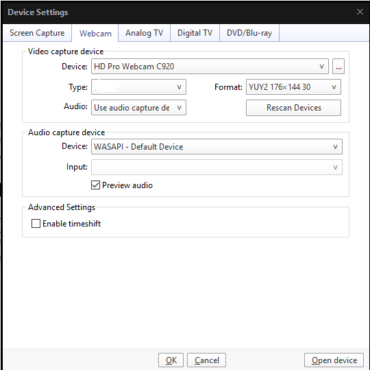
After ko is loaded successfully, the /dev/video0 node will be generated. Connect the USB device port of the board to the PC with a USB cable. Run the UVC demo and use a player such as PotPlayer to open the camera device, the UVC Camera device will appear.
6. USB 2.0 hardware simulation parameters adjustment
The following situations require consideration of adjusting driver capabilities:
-
If the eye diagram template test fails or is not aesthetically pleasing, modify the driver capabilities to achieve better test results.
-
If you encounter issues such as partial USB2 connection failures, communication interruptions, or other probabilistic USB2-related problems, and you want to try modifying the driver capabilities, this essentially boils down to point 1. However, due to the lack of eye diagram testing capabilities, black-box testing may be necessary for some devices.
6.1. Tx swing trim (This parameter may have been trimmed in OTP, so please confirm with hardware RD before adjusting this parameter).
The parameter swing trim is located in UTMI bank offset 0x44[9:4]. Parameter range: 0 ~ 63.
-
Query the current value: cat /sys/kernel/debug/usb/phy-soc\:sstar-usb2-phy.0/swing_trim
-
Set the value: echo value > /sys/kernel/debug/usb/phy-soc\:sstar-usb2-phy.0/swing_trim
6.2. pre_emphasis
The parameter pre_emphasis is located in UTMI bank offset 0x43[9:8]. Parameter range: 0 ~ 3. The larger the value, the stronger the pre-emphasis is.
-
Query the current value: cat /sys/kernel/debug/usb/phy-soc\:sstar-usb2-phy.0/pre_emphasis
-
Set the value: echo value > /sys/kernel/debug/usb/phy-soc\:sstar-usb2-phy.0/pre_emphasis
6.3. Eye Diagram Test
-
After booting the device, enter the kernel and run the following commands, and then you can connect with an oscilloscope to view the eye diagram.
-
When the waveform result of eye diagram test does not meet the requirements, you can adjust the above five parameters until the waveform is perfect.
To perform highspeed eye diagram test, run: echo “hs” > /sys/kernel/debug/usb/phy-soc\:sstar-usb2-phy.0/eye_diagram_switch
To perform fullspeed eye diagram test, run: echo “fs” > /sys/kernel/debug/usb/phy-soc\:sstar-usb2-phy.0/eye_diagram_switch
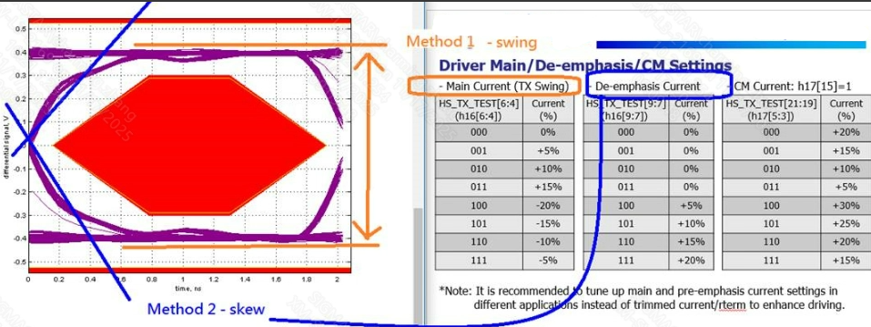
6.4. Tx swing and pre_emphasis Parameter meaning
-
TX swing: As shown in the image above, this refers to the part marked in yellow. It mainly involves adjusting the eye height (adjusting the level of the DM DP differential signal, which is closest to the concept of USB2 drive capability). If the eye height test results do not meet the requirements, the corresponding modification methods can be provided (the higher the intensity of the opening, the wider the corresponding eye height opening).
-
De-emphasis Current: As shown in the image above, this refers to the section marked in blue. It mainly modifies the waveform's rise/fall speed (de-emphasis design in high-speed signal transmission). If there are cases where the rising/falling waveform is pressing against the eye diagram, this part can be adjusted (the higher the opening strength, the steeper the corresponding waveform).
6.5. Tx swing and pre_emphasis automatic configuration
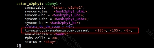
    text:
        tx-swing,de-emphasis,cm-current = <105>, <105>, <0>;
As shown in the image above, once the eye diagram test passes, the optimal solution will be obtained. After configuring it in DTSI, it will automatically configure upon startup and take effect permanently.
7. Debug & FAQ
Q1:Unable to recognize USB host connected device under kernel
-
Check if the VBUS power supply has been pulled up
-
Check if the
statusof DTS ehci node isOK -
Check if the kernel config is configured
Q2:High speed devices recognized as full speed in the kernel
- Check if the upper level of the device is connected to the full speed hub
Q3:U-disk upgrade failed under uboot
-
Check if the VBUS power supply has been pulled up
-
Check if the
statusof DTS ehci node isOK -
Check if the USB drive is in FAT32 format
Q4:USB empty chip upgrade failed
-
Check if it is in an empty upgrade state, the serial port will print a log(Start USB Mode) for the empty upgrade state
-
Check if the packaged USB image matches the board