Ethernet User Guide
REVISION HISTORY
| Revision No. | Description |
Date |
|---|---|---|
| 1.0 | 11/25/2025 |
1. Overview
Ethernet Media Access Controller (EMAC) is responsible for controlling and managing the physical layer and the data link layer in Ethernet data communications.
From the hardware perspective:
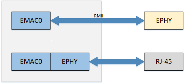
The hardware architecture is shown in the figure. There is only one EMAC controller: EMAC0.
EMAC0: Supports MII internal Ephy (100M), RMII external Ephy (100M)
From the software perspective (default settings):
-
UBOOT
EMAC0: MII
-
KERNEL
EMAC0: MII
2. Keyword Description
-
EMAC
Ethernet Media Access Controller
-
Ephy
Ethernet Physical Layer is referred to as Ephy
-
MII
MII (Media Independent Interface) is a standard interface for connecting MAC and PHY. MII interface provides interconnection support between MAC and PHY
-
RMII
RMII (Reduced Media Independent Interface) is a simplified media independent interface, which is one of the standard Ethernet interfaces and has fewer I/O transmission pins than MII.
-
RX
Receiver or Reception.
-
TX
Transmitter or Transmission.
-
MDIO
MDIO (Management Data Input/Output), a bidirectional interface for management data input and output.
-
MDC
MDC (Management Data Clock), is the clock signal for management data.
3. EMAC Function Description
3.1. FLOW CONTROL
Data loss may occur easily during the transmission process. For example, when two computers transmit data through serial ports, or when a desktop computer communicates with a single-chip microcomputer, the data buffer at the receiving end may be full due to the different processing speeds of the computers at both ends, while the sending end continues to send data, resulting in data loss.
Flow control is used to solve the problem of data loss. In full-duplex applications, flow control is performed through PAUSE frames.
When the receiving end cannot process the data, it sends a "no more receiving" signal (PAUSE frame), and the sending end stops sending until it receives a "can continue sending" signal. Therefore, flow control can control the progress of data transmission and prevent data loss. The PAUSE frame is a packet that implements flow control at the link layer and is automatically processed by the link.
For example, when a 100M network card sends data frames to a 10M network card through a switch, the 10M network card may suffer from buffer overflow due to rate limitations. When the 10M network card finds that its buffer is about to overflow, it can send a PAUSE frame, asking the device that receives the PAUSE frame to pause for a while before sending packets.
3.1.1. PAUSE frame format
The format of the PAUSE frame is shown in the following figure:
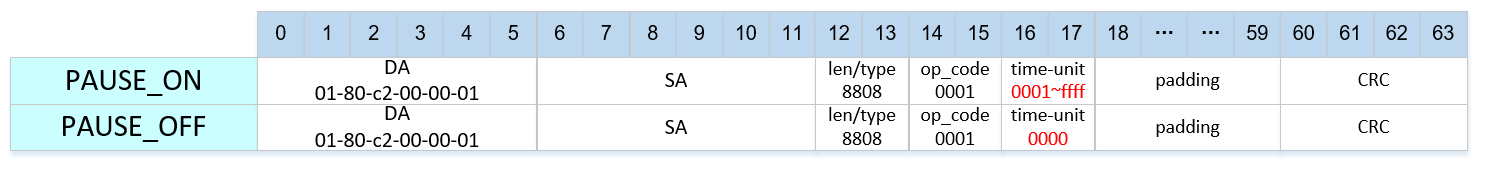
If it is PAUSE_ON pkt, time_unit is not 0. Currently the default is 0xFFFF.
If it is PAUSE_OFF pkt, then time_unit is 0. When PAUSE_OFF pkt is received, it means that flow control has been turned off and tx pkt can be normally performed, that is, it has the wake-up function.
time-unit is the transmission pause time parameter, the unit is the time to transmit 512 bits at the current rate, that is, slot time; some common values can be found in the table below.
| value | 10M pause time | 100M pause time |
|---|---|---|
| 20 | 1ms | 100us |
| 200 | 10ms | 1ms |
| 2000 | 100ms | 10ms |
| 20000 | 1s | 100ms |
| 60000 | 3s | 300ms |
| 65535 | 3.27s | 327ms |
3.1.2. How to enable PAUSE shutdown
-
Hardware FLOW CONTROL can be switched on and off via the macro HW_FLOW_CONTROL in hal_emac.h .
-
Can be controlled by ethtool, tx refers to the transmission direction flow control, indicating whether eth0 can pause the transmission when it receives a PAUSE frame while transmitting traffic; rx refers to the receiving direction flow control, indicating whether eth0 can send a PAUSE frame to the other end when receiving traffic.
./ethtool -a eth0               => Display the current flow control status
./ethtool -A eth0 rx on tx on   => Turn on flow control for tx and rx
./ethtool -A eth0 rx off tx off => Turn off tx rx flow control
3.2. NETWORK STORM
Broadcast storm: refers to broadcast data that floods the network and cannot be processed, occupying a large amount of network bandwidth, causing normal business to be unable to run or even completely paralyzed.
To solve this problem, you can enable the network storm protection function, and the network card can limit the sending and receiving bandwidth of unicast, multicast, and broadcast. For broadcast storm scenarios, you can choose to use broadcast traffic limit to solve the problem.
- Network storm can be switched through the macro HW_FLOW_CONTROL and NETWORK_STORM_PROTECT_DEBUG in hal_emac.h. Unicast storm is disabled by default.
3.2.1. Packet filtering rate
At 100M rate, RX_CLK = 25MHz . At 10M rate, RX_CLK = 2.5MHz .
NETWORK STORM = RX_CLK / filter value (consume), the current default filter value is 2500.
Therefore, the default value of the rate limit at 100M is 25MHz / 2500 = 10000 Packets/s. When the default value does not meet the requirements, you can modify the filter value to get the desired rate limit.
max means that (max/consume) packets can be received at full speed at the beginning. When this many packets are received, the subsequent packet receiving rate is as described above (RX_CLK / consume).
3.2.2. How to set the packet filtering rate
Currently, five levels are provided by default
| Level | Consume | Rate Limit for 100M Packets/s | Rate Limit for 10M Packets/s |
|---|---|---|---|
| 1 | 40000 | 625 | 62.5 |
| 2 | 20000 | 1250 | 125 |
| 3 | 10000 | 2500 | 250 |
| 4 | 5000 | 5000 | 500 |
| 5 | 2500 | 10000 | 1000 |
3.2.3. Enabling Network Storm Protection Using the Register
If it does not meet the customer's needs, the following provides a set of default settings, which can be freely adjusted according to the method. If you want to enable them at the same time, just turn on the corresponding enable bit. The following takes iford as an example:
3.2.3.1. emac0
-
Unicast single packet protection
/customer/riu_w 1511 50 1A80 // Maximum value max lower 16 bits /customer/riu_w 1511 51 0006 // Maximum value max high 16 bits /customer/riu_w 1511 52 09C4 // Filter value consume lower 16 bits /customer/riu_w 1511 68 0001 // bit 0 enable-
multicast multi-packet protection
/customer/riu_w 1511 58 1A80 // Maximum value max lower 16 bits /customer/riu_w 1511 59 0006 // Maximum value max high 16 bits /customer/riu_w 1511 5A 09C4 // Filter value consume lower 16 bits /customer/riu_w 1511 68 0002 // bit 1 enable
-
-
broadcast packet protection
/customer/riu_w 1511 60 1A80 // Maximum value max lower 16 bits
/customer/riu_w 1511 61 0006 // Maximum value max high 16 bits
/customer/riu_w 1511 62 09C4 // Filter value consume lower 16 bits
/customer/riu_w 1511 68 0004 // bit 2 enable
3.3 Network receive interrupt aggregation
When the EMAC RX hardware receives a frame, it triggers an interrupt to wake up the RX thread for packet reception. During high network traffic, a large number of interrupts are generated, which consumes significant CPU performance and increases CPU load.
The EMAC hardware provides a receive interrupt aggregation function (sometimes referred to as RX DELAY). Its mechanism allows the EMAC to delay triggering an interrupt immediately after receiving a frame; instead, the interrupt is triggered only when either of the following conditions is met:
-
The number of received frames reaches the set threshold (delay_num)
-
The set number of frames is not reached, but the specified time (cyc_num) has elapsed
This mechanism reduces the number of receive interrupts, thereby saving CPU resources.
In addition, the RX Delay feature includes an internal dynamic adjustment function:
-
During network idle periods, delay_num and cyc_num are automatically set to smaller values
-
During network busy periods, delay_num and cyc_num are automatically set to larger values
This dynamic adjustment function can be controlled on/off by adjusting the rx-delay-int attribute in DTS
-
Set rx-delay-int to 1, the receive interrupt aggregation function is turned on (enabled by default)
-
Set rx-delay-int to 0, the receive interrupt aggregation function is turned off
3.4. IPV6
The kernel provides the ipv6 function. If you need to use the ipv6 function, you need to enable the corresponding CONFIG.
- Enable ipv6 support in kernel
-> Networking support (NET [=y])
    -> Networking options
        -> TCP/IP networking (INET [=y])
            <*>   The IPv6 protocol
4. Hardware connection introduction
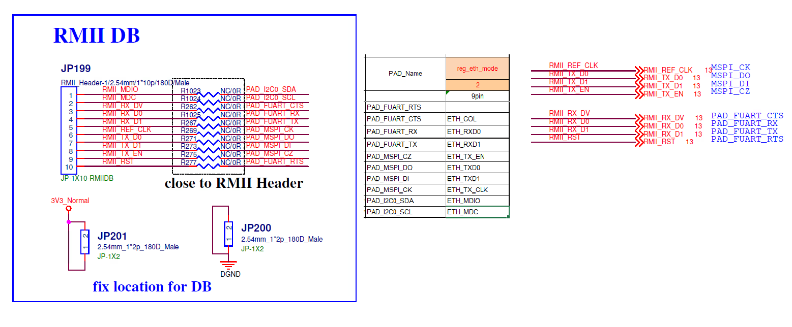
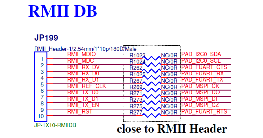
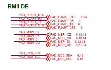
RMII wiring is as shown below:
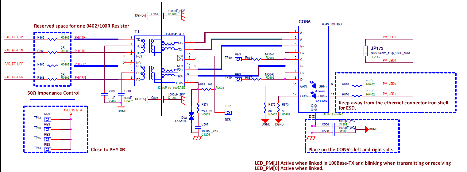
MII wiring is as shown below:
5. Uboot usage introduction
5.1. Uboot CONFIG Configuration Instructions
-
EMAC related CONFIG configuration
SigmaStar drivers  --->
    [*]   SigmaStar EMAC
    [ ]     EMAC 1
    [ ]   EMAC supply to internel PHY
    [ ]   EMAC supply to RMII
    [ ]   EMAC supply to IC+ Phy
    [ ]   EMAC fix link to mii/rmii
CONFIG Description Default Value Remark [*] SigmaStar EMAC Enable EMAC0 Enable [ ] EMAC 1 Enable EMAC1 Disable Iford does not have EMAC1 network card, no configuration required [ ] EMAC supply to internel PHY Enable internel PHY Disable The internal PHY is configured to be used by default. [*] EMAC supply to RMII Enable RMII mode Enable [ ] EMAC supply to IC+ Phy Support ICPULS PHY Disable [ ] EMAC fix link to mii/rmii Enable fix link Disable -
EMAC0 RMII
SigmaStar drivers ---> [*] SigmaStar EMAC [ ] EMAC 1 [ ] EMAC supply to internel PHY [*] EMAC supply to RMII [ ] EMAC supply to IC+ Phy [ ] EMAC fix link to mii/rmii -
To switch the network port to RMII mode, enable the RMII padmux pin in the padmux.dtsi file for the corresponding board model, as shown below.

Figure 5-1 RMII padmux pins -
Network commands
Command line interface --->
    Network commands --->
        [*]   bootp
        [*]     dhcp
        [*]   tftpboot
        [*]   ping
5.2. Uboot cmd parameter description
The network under Uboot mainly uses the ping dhcp tftp commands. Before using these commands, you need to configure the environment variables used by the network.
5.2.1. ENV configuration to automatically initialize the network card at startup
You can use the environment variable autoestart to configure the automatic initialization of the network card at startup. However, since the network card initialization will wait for the network card auto-negotiation to complete, it will cause the startup speed to slow down. You need to decide whether to configure it according to your needs.
If autoestart=0, the network card will not be initialized when booting. If you need to use the network under uboot, you need to execute the estart command to initialize the network card, otherwise it will prompt: No ethernet found.
estart // Network card initialization
If autoestart=1, the network card will be automatically initialized when the computer starts.
setenv -f autoestart 1 //Configure automatic initialization of the network card at startup
5.2.2. ENV configuration static IP
setenv -f ethaddr xx:xx:xx:xx:xx:xx:xx //Configure mac address
setenv -f ipaddr xxx.xxx.xxx.xxx //Configure static IP address
setenv -f netmask xxx.xxx.xxx.xxx //Configure IP address mask
setenv -f serverip xxx.xxx.xxx.xxx //Configure tftp server ip
save //Save configuration
5.2.3. ENV configuration & dynamic IP acquisition
setenv -f ethaddr xx:xx:xx:xx:xx:xx:xx //Configure mac address
setenv -f serverip xxx.xxx.xxx.xxx //Configure tftp server ip
save //Save configuration
dhcp //dhcp dynamically obtains ip
5.2.4. tftp command
tftp 0x20000000 kernel // means copy the file named kernel on the server to address 0x20000000 via tftp
5.2.5. ping command
ping '<ip-address>' //Ping the specified IP address. If ping succeeds, it will prompt "host <ip> is alive"
6. Kernel usage introduction
6.1. Kernel CONFIG configuration
-
Enable EMAC driver
Device Drivers ---> Sstar Soc platform drivers ---> <*> SSTAR_EMAC -
Enable nfs cifs
File systems --->
    Network File Systems --->
        <M> NFS client support
        <M>     NFS client support for NFS version 2
        <M>     NFS client support for NFS version 3
        <M> SMB3 and CIFS support
6.2. Kernel DTS Configuration
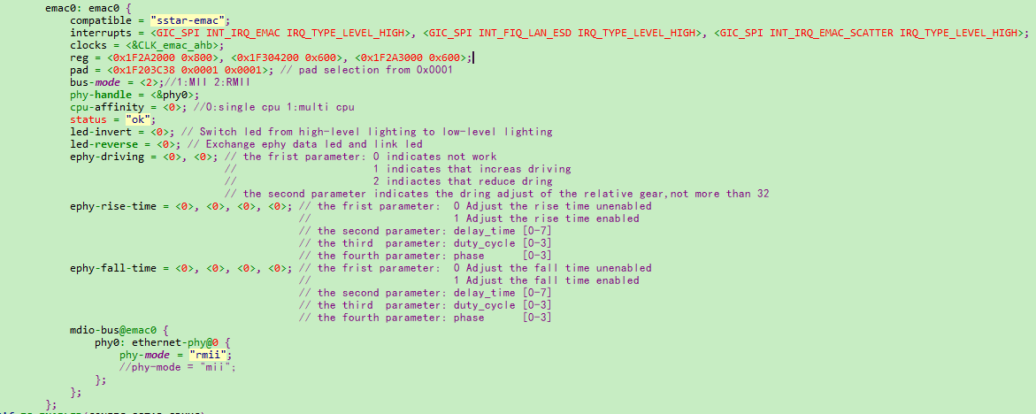
| Parameter | Description | Remarks |
|---|---|---|
| compatible | Property Information | Corresponds to driver property values |
| interrupts | Interrupt Pins | interrupt trigger pin driver acquisition |
| clocks | EMAC Clock | Driver gets clock node |
| reg | Physical address of register map | The first is emac register base, the second is x32 register base, the third is internal phy register base |
| pad | padmux | This takes effect when CONFIG_SSTAR_PADMUX and EMAC_PADMUX_ENABLE are not enabled |
| bus-mode | The mode selected by mac is the same as phy | 1:MII 2:RMII |
| phy-handle | PHY Node | |
| cpu-affinity | CPU affinity; allows interrupts to be handled on multiple CPUs when enabled | 0: single CPU 1: multi CPU |
| status | Driver Switch | "ok"/"disabled" |
| led-invert | Configure whether the ePHY LED is turned on by a high level or switched to a low level | 0: High level on 1: Low level on |
| led-reverse | swap data LED and link LED | 0: No flip 1: Flip |
| ephy-driving | Adjust the driving capability of ePHY | <parameter 1>:enable/disable <parameter 2>: ephy driving level The default parameter configuration is 0 |
| ephy-rise-time | Adjust the rise time of ePHY | <parameter 1>:enable/disable <parameter 2>: delay_time [0~7] <parameter 3>: duty_cycle [0~3] <parameter 4>: phase [0~3] The default parameter configuration is 0 |
| ephy-fall-time | Adjust the fall time of ePHY | <parameter 1>:enable/disable <parameter 2>: delay_time [0~7] <parameter 3>: duty_cycle [0~3] <parameter 4>: phase [0~3] The default parameter configuration is 0 |
| phy-mode | PHY Interface Selection | "mii"/"rmii" |
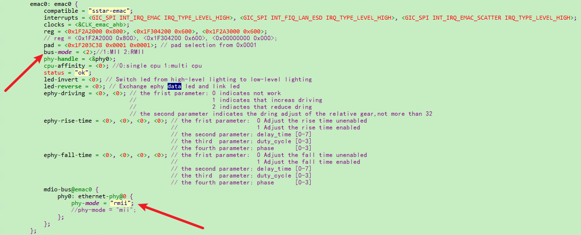
6.2.1 Example of enabling EMAC0 on a DTS node
DTS Configuration: modify "EMAC0" dts node
-
modify bus-mode to RMII mode
-
modify phy-mode to RMII mode
- PADMUX DTSI Configuration: find EMAC0 padmux.dtsi file,open the pins corresponding to eth0 and disable any conflicting pins.

6.3. Padmux Configuration
The padmux method of EMAC configuring RMII is the same in Uboot and kernel. You only need to add the following code to the corresponding padmux.dtsi according to the selected pin:
- RMII PADMUX configuration for EMAC0 :
<PAD_I2C0_SDA            PINMUX_FOR_ETH_MODE_2           MDRV_PUSE_ETH0_MDIO>,
<PAD_I2C0_SCL            PINMUX_FOR_ETH_MODE_2           MDRV_PUSE_ETH0_MDC>,
<PAD_FUART_CTS           PINMUX_FOR_ETH_MODE_2           MDRV_PUSE_ETH0_COL>,
<PAD_FUART_RX            PINMUX_FOR_ETH_MODE_2           MDRV_PUSE_ETH0_RXD0>,
<PAD_FUART_TX            PINMUX_FOR_ETH_MODE_2           MDRV_PUSE_ETH0_RXD1>,
<PAD_MSPI_CK             PINMUX_FOR_ETH_MODE_2           MDRV_PUSE_ETH0_TX_CLK>,
<PAD_MSPI_DO             PINMUX_FOR_ETH_MODE_2           MDRV_PUSE_ETH0_TXD0>,
<PAD_MSPI_DI             PINMUX_FOR_ETH_MODE_2           MDRV_PUSE_ETH0_TXD1>,
<PAD_MSPI_CZ             PINMUX_FOR_ETH_MODE_2           MDRV_PUSE_ETH0_TX_CTL>,
<PAD_FUART_RTS           PINMUX_FOR_GPIO_MODE            MDRV_PUSE_ETH0_PHY_RESET>,
6.4. Kernel cmd usage examples
-
View all network card information
ifconfig -a -
eth0 network card enabled
ifconfig eth0 up -
Configure the MAC address of the network card eth0 to 00:00:88:33:00:01
ifconfig eth0 hw ether 00:00:88:33:00:01 -
Configure the static IP address of network card eth0 to 40.1.1.1/24
ifconfig eth0 40.1.1.1 netmask 255.255.255.0 -
Network card eth0 DHCP obtains IP
udhcpc -i eth0 -s /etc/init.d/udhcpc.script -
Mount nfs directory
mount -t nfs -o nolock xxx.xxx.xxx.xxx:/c/nfs /mntParameters Description xxx.xxx.xxx.xxx nfs server ip address /c/nfs Directory path of the nfs server /mnt Mount the nfs directory on the /mnt path of the device -
Mount the cifs directory
mount -t cifs //xxx.xxx.xxx.xxx/cifs /mnt -o username=xxx,password=xxx,sec=ntlm,iocharset=utf8,vers=1.0Parameters Description xxx.xxx.xxx.xxx cifs server ip address /cifs cifs server shared directory path /mnt Mount the cifs directory on the /mnt path of the device -
tftp get
tftp -g xxx.xxx.xxx.xxx -r kernelParameters Description -g xxx.xxx.xxx.xxx Get files from server_ip xxx.xxx.xxx.xxx -r file_name The file name to be obtained from the Server -
tftp put
tftp -p xxx.xxx.xxx.xxx -r kernelParameters Description -p xxx.xxx.xxx.xxx Transfer files to xxx.xxx.xxx.xxx -r file_name The file name to be transferred to the Server -
Configure eth0 to obtain dynamic IP and mount nfs

Figure 6-4 kernel_nfs_cmd
6.5. Common third-party tools and common commands
6.5.1. iperf3
-
iperf3 server mode
./iperf3 -s -i 1Options Description -s Server mode -i 1 Print echo interval (unit: seconds), here is 1 second -
iperf3 client mode
./iperf3 -c xxx.xxx.xxx.xxx -i 1 -t 36000 -b 95MOptions Description -c client mode xxx.xxx.xxx.xxx peer's IP address -i 1 Print echo interval, in seconds, here is 1 second -t 36000 Streaming time, in seconds, up to 86400 (24 hours) -b 95M Stream rate 95Mbits/sec
6.5.2. tcpdump
tcpdump is a packet capture tool under Linux.
./tcpdump -s 0 -i eth0 -w /tmp/pkt.cap //Capture packets from eth0 network card and cache them in pkt.cap
| Option | Description |
|---|---|
| -s 0 | Specifies the size of the captured packet, 0 means no limit |
| -i eth0 | Indicates the connected interface, any means all interfaces |
| -w /tmp/pkt.cap | Indicates that the captured packet is written to the specified path. The file is .pcap |
6.5.3. ethtool
-
View eth0 network card information
ethtool eth0 -
Switch the eth0 network card speed and duplex mode
ethtool -s eth0 speed 100 duplex full -
Enable/disable eth0 auto-negotiation
ethtool -s eth0 autoneg on/off -
Enable Flow Control
ethtool -A eth0 rx on tx on -
View eth0 packet receiving statistics
ethtool -S eth0
6.5.4. phytool
-
Read the value of phy reg
read IFACE/ADDR/REGOptions Description IFACE eth0 or eth1 ADDR Location on mdio bus REG Read phy reg eg: read eth0 addr0 reg2
phytool read eth0/0/2 -
Write value to phy reg
write IFACE/ADDR/REG <0-0xffff>Parameters Description IFACE eth0 or eth1 ADDR Location on mdio bus REG phy reg written <0-0xffff> Value to write Eg: write the loopback bit of eth0
phytool write eth0/0/0 4000
6.6. Commonly used DEBUG nodes
6.6.1. dlist emac driver statistics node
Use cat dlist to view information such as emacs driver interruption/packet reception statistics.
/ # cat /sys/devices/virtual/sstar/emac0/dlist_info
RBQP_size=0x100
empty=0x100, hemac->rxBuffIndex=0x7d, u32RBQP_Addr=0x7fca07d
0x000: 1111111111111111 1111111111111111
0x020: 1111111111111111 1111111111111111
0x040: 1111111111111111 1111111111111111
0x060: 1111111111111111 1111111111111111
0x080: 1111111111111111 1111111111111111
0x0a0: 1111111111111111 1111111111111111
0x0c0: 1111111111111111 1111111111111111
0x0e0: 1111111111111111 1111111111111111
max_rx_packet_count=4
max_tx_packet_count=1
IDX_CNT_INT_DONE=0
IDX_CNT_INT_RCOM=0
IDX_CNT_INT_RBNA=0
IDX_CNT_INT_TOVR=0
IDX_CNT_INT_TUND=0
IDX_CNT_INT_RTRY=0
IDX_CNT_INT_TCOM=0
IDX_CNT_INT_ROVR=0
IDX_CNT_JULIAN_D=13601
IDX_CNT_INT_TDLY=0
IDX_CNT_INT_TDTO=0
skb_tx_send=7079
skb_tx_free=7079
skb_ip_checksum_err=0
skb_tcp_checksum_err=0
skb_udp_checksum_err=0
rx_duration_max=60641
rx_packet_cnt=13693
tx_delay_pack_cnt=0
data_done=391261
data_duration=6474857
data_average=0
tx_pkt (duration)=7079
tx_int (duration)=0
tx_int_dly (duration)=0
tx_int_to (duration)=0
rx_int_dly (duration)=13601
rx_pkt (duration)=13693
Hal_EMAC_TXQ_Mode=0
maxSG=3
6.6.2. phyStatusWR phy reads and writes debug nodes
-
Usage
/ # cat /sys/devices/virtual/sstar/emac0/phyStatusWR phy read & write: Usage: echo phy_r phyAddress > phyStatusWR echo phy_w phyAddress phyValue> phyStatusWR echo phyE_r phyId phyAddress > phyStatusWR echo phyE_w phyId phyAddress phyValues > phyStatusW -
eg
/sys/devices/virtual/sstar/emac0 # echo phy_r 0 > phyStatusWR
phy_r address[0] value[3100]
/sys/devices/virtual/sstar/emac0 # echo phy_w 0  0x1200 > phyStatusWR
phy_w address[0] value[1200]
/sys/devices/virtual/sstar/emac0 # echo phyE_r 0 0 > phyStatusWR
phyE_r id[0] address[0] value[3100]
/sys/devices/virtual/sstar/emac0 # echo phyE_w 0 0 0x1200 > phyStatusWR
phyE_w id[0] address[0] value[1200]
6.6.3. turndrv drives debug nodes
- Usage
/sys/devices/virtual/sstar/emac0 # cat turndrv
Usage:
        echo f10t    > turndrv => set max_speed to 10M
        echo an      > turndrv => set link mode to autonegotiation
        echo dir_on  > turndrv => enable  Dynamic Rx Interrupt
        echo dir_off > turndrv => disable Dynamic Rx Interrupt
        echo swing_100 [gear]  > turndrv => swing 100M tx gear
        echo swing_10  [gear]  > turndrv => swing 10M tx gear
        echo rx_imp    [level] > turndrv => adjust rx impedance, range:-4 ~ 7
        echo timing    [is_rise] [delay_time] [duty_cycle] [phase] > turndrv
6.6.3.1. f10t limits the maximum rate to 10Mbits/sec
An auto-negotiation is required to switch to 10M
/ # echo f10t > /sys/devices/virtual/sstar/emac0/turndrv
SPEED_10
/ # echo an > /sys/devices/virtual/sstar/emac0/turndrv
phy_start_aneg
6.6.3.2. an performs auto-negotiation
/ # echo an > /sys/devices/virtual/sstar/emac0/turndrv
phy_start_aneg
6.6.3.3. dir_on turns on RX DELAY to dynamically adjust the threshold
/ # echo dir_on > /sys/devices/virtual/sstar/emac0/turndrv
rx_stats_enable: 1
6.6.3.4. dir_off Turn off RX DELAY dynamic adjustment threshold
/ # echo dir_off > /sys/devices/virtual/sstar/emac0/turndrv
rx_stats_enable: 0
7. External phy porting
7.1. Overview
During the customer support process, it is inevitable to encounter the need to adapt a new off-chip phy, so this article explains the precautions for adapting an off-chip phy.
Before reading this chapter, you can first check Overview to understand the relevant specifications
7.2. Hardware circuit
-
Confirm that the physical connection of the pin is normal. You can measure the signal through an oscilloscope. You can consult HW CAE for this step.
-
Padmux confirmation pairing. You can consult GPIO owner or HW CAE to confirm the correctness of padmux.
-
The external crystal frequency of phy is generally 25M, but the specific frequency needs to be confirmed according to the phy manual. The chip does not provide CLK.
7.3. Obtain necessary PHY original support before adaptation
7.3.1. Phy driver
After getting a new phy chip, you need to find the original manufacturer to provide matching phy chip manual .
Some phy chips also require matching phy drivers . If you do not need a matching phy driver, you can use the default general phy driver.
If you already have a relevant phy driver, you also need to consult the original manufacturer whether you need to update the corresponding driver .
If you need to update, this part of information also needs to be supported by the phy original manufacturer, mainly providing: corresponding code, update method, method of enabling the driver, special settings and configuration, etc.
After the kernel runs after the driver is updated, use the command: ls /sys/bus/mdio_bus/drivers to confirm whether the driver has been successfully updated.
ls /sys/bus/mdio_bus/drivers
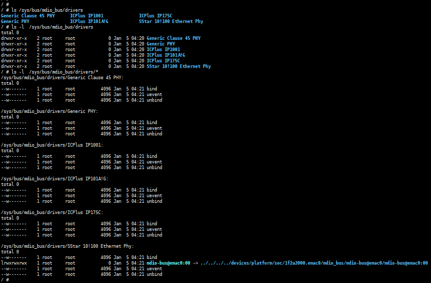
As shown in Figure 7-1, you can see that the default driver is matched: SStar 10!100 Ethernet Phy.
7.3.2. reset timing
Ask the manufacturer or look up the phy chip manual to find the timing requirements for phy reset.
-
Reset effective time: how long it takes to pull down. The current EMAC defaults to pulling down 20ms.
-
Reset recovery time: how long it takes to keep pulling up. How long does it take for the phy chip to complete the internal circuit initialization after the phy chip is reset. The current EMAC defaults to pulling up 50ms.
Take RTL8211 as an example:
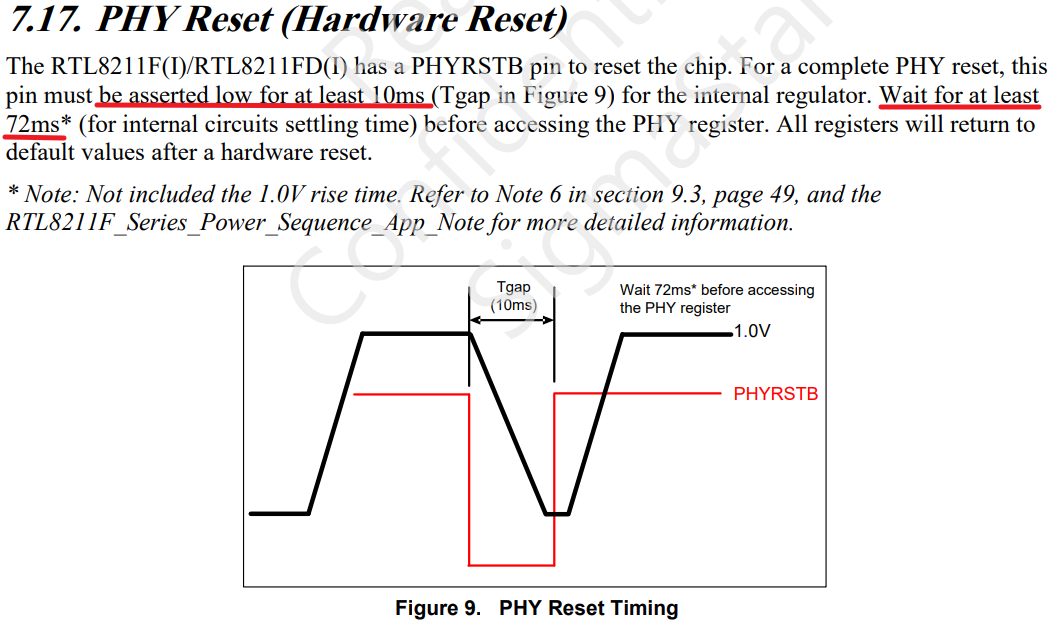
As indicated by the red line in Figure 7-2, RTL8211 requires: reset effective time is at least 10ms, reset recovery time is at least 72ms.
7.4. Introduction to Uboot adaptation
7.4.1. padmux configuration under Uboot
- It is necessary to match padmux.dtsi with the hardware circuit.
Take SSC029A-S01A-S as an example, find the corresponding pins of eth0 and eth1, and write their mapping relationship into the iford-padmux.dtsi file.
- eth0 padmux
<PAD_I2C0_SDA            PINMUX_FOR_ETH_MODE_2           MDRV_PUSE_ETH0_MDIO>,
<PAD_I2C0_SCL            PINMUX_FOR_ETH_MODE_2           MDRV_PUSE_ETH0_MDC>,
<PAD_FUART_CTS           PINMUX_FOR_ETH_MODE_2           MDRV_PUSE_ETH0_COL>,
<PAD_FUART_RX            PINMUX_FOR_ETH_MODE_2           MDRV_PUSE_ETH0_RXD0>,
<PAD_FUART_TX            PINMUX_FOR_ETH_MODE_2           MDRV_PUSE_ETH0_RXD1>,
<PAD_MSPI_CK             PINMUX_FOR_ETH_MODE_2           MDRV_PUSE_ETH0_TX_CLK>,
<PAD_MSPI_DO             PINMUX_FOR_ETH_MODE_2           MDRV_PUSE_ETH0_TXD0>,
<PAD_MSPI_DI             PINMUX_FOR_ETH_MODE_2           MDRV_PUSE_ETH0_TXD1>,
<PAD_MSPI_CZ             PINMUX_FOR_ETH_MODE_2           MDRV_PUSE_ETH0_TX_CTL>,
<PAD_FUART_RTS           PINMUX_FOR_GPIO_MODE            MDRV_PUSE_ETH0_PHY_RESET>,
7.4.2. EMAC RMII configuration under Uboot
-
external phy needs to enable macro SSTAR_ETHERNET_RMII and switch rmii mode。
-
EMAC0 RMII
[*] SigmaStar drivers ---> [*] SigmaStar EMAC [ ] EMAC 1 [ ] EMAC supply to internel PHY [*] EMAC supply to RMII [ ] EMAC supply to IC+ Phy [ ] EMAC fix link to mii/rmii -
需要 iford-padmux.dtsi 文件中打开 EMAC0 RMII padmux引脚。
For more detailed KCONFIG configuration content, please refer to Uboot CONFIG Configuration Instructions.
7.4.3. Check if mdio communication is normal
If phy connection is normal, mdio can read phy information normally. When using command estart in Uboot for initialization, phy register information will be printed, and the information is not all 0 or all F.
Or use phy_r and phy_w commands to read phy register information normally, and the information is not all 0 or all F.
-
Uboot is initialized normally using estart command
SigmaStar # estart phy [0]=ffff phy [1]=7849 MAC Address 00:00:88:33:00:01 Auto-Negotiation... Link Status Speed:100 Full-duplex:1 (Re)start EMAC... -
Use phy_r to read phy reg in Uboot
# phy_r 0 phy read address[0] value is 3100 # phy_r 1 phy read address[1] value is 786d -
Use phy_w to write phy reg in Uboot
# phy_w 0 0x1000
phy write address[0] value is 1000
7.4.4. Check if network communication is normal
This step is to verify the correctness of the data pin, which can be verified by ping (normal ping) or tftp (normal file transfer or upgrade).
For related content, please refer to Uboot cmd parameter description.
7.5. Introduction to Kernel adaptation
7.5.1. Phy reset time configuration under Kernel
The reset effective time and reset recovery time under kernel are also configured through Kconfig.
EMAC0_PHY_RESET_HOLD_MS and EMAC1_PHY_RESET_HOLD_MS are reset effective time, the default value is 20ms.
EMAC0_PHY_RESET_WAIT_READY_MS and EMAC1_PHY_RESET_WAIT_READY_MS are reset recovery time, the default value is 50ms.
- Configure the kernel reset effective time and reset recovery time
Device Drivers --->
    Sstar Soc platform drivers --->
        (20)  Set emac0 phy reset padmux low in millisecond
        (50)  Set emac0 phy reset padmux high wait ready in millisecond
        (20)  Set emac1 phy reset padmux low in millisecond
        (50)  Set emac1 phy reset padmux high wait ready in millisecond
7.5.2. DTS configuration under Kernel
Refer to Kernel DTS configuration to configure the DTS file.
Note that if an external reverse circuit is connected, the reset_reverse property needs to be configured.
7.5.3. Padmux configuration under Kernel
Refer to padmux configuration under Uboot or Kernel Padmux configuration to configure the padmux file.
7.5.4. Check whether mdio communication is normal
The kernel will connect to the phy chip through the emac_phy_connect function. You can check the boot log to see if it is connected to the phy normally.
Taking SSC029A-S01A-S as an example, the machine will connect to phy at startup, obtain the phy uid and match the phy driver. Generally, if the phy uid is not all 0 or all F, the phy reg information can be read normally.
- dmesg to view the phy connect status
/customer # dmesg | grep emac_phy_connect
[emac_phy_connect][3004] connected mac emac0 to PHY at mdio-bus@emac0:00 [uid=11112222, driver=SStar 10/100 Ethernet Phy]
In addition, you can also read phy reg through phytool or debug node. As long as the read phy reg is not all 0 or all F, it is normal.
For the use of phytool, please refer to phytool.
For debug node commands, please refer to phyStatusWR.
7.5.5. Check if network communication is normal
The iperf tool can be used under kernel to test the stability of network communication. Please refer to iperf3.
7.6. Common phy adaptation problems
7.6.1. mdio read abnormality, phy id read information is all F or all 0
During the adaptation process, there is often a problem of not being able to read phy reg, and the signals sent out by mdc and mdio are all FFFF or all 0.
It is recommended that HW CAE intervene to assist in checking the measurement waveform and circuit connection.
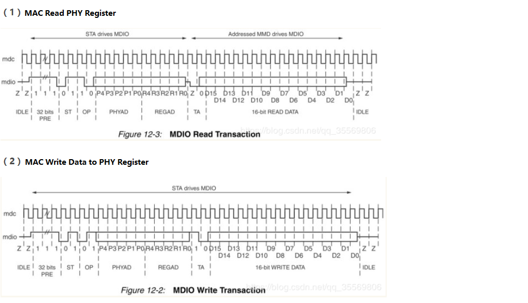
The normal mdio waveform is shown in the figure. When this problem occurs, it is necessary to combine the waveform to check. It is recommended that HW CAE intervene to assist in checking the measurement waveform and circuit connection.
Common errors have the following reasons:
| Cause of error | Troubleshooting method | Solution |
|---|---|---|
| Physical connection abnormality | HW CAE assists in measuring waveforms, or checking circuit connections | Refer to HW CAE opinions |
| GPIO configuration abnormality | HW CAE checks padmux mapping | Modify padmux |
| GPIO cannot be pulled down or raised | Troubleshoot according to gpio problems, you can ask GPIO owner for assistance | Solve according to GPIO problems |
| Phy reset abnormality | Use an oscilloscope to measure whether the waveform of the reset pin at startup meets expectations | Refer to the phy manual for settings. In the debug stage, you can set the reset effective time and recovery time to 1s or more to ensure that the reset is normal |
7.6.2. The rate of receiving and sending packets is not as expected, or there are problems such as packet loss
If the rate is not as expected, it is usually a signal quality problem or a phase problem, which needs to be led by HW CAE. Here are some common troubleshooting items:
-
Confirm whether the CLK provided by phy/switch is 50MHz. The MAC does not provide RX_CLK.
-
Confirm the signal amplitude or phase. If the waveform is abnormal, you need to refer to the phy manual and adjust the driving capability of the phy by adjusting the phy register.
-
Check the external crystal oscillator of phy, which is generally 25M, but it depends on the phy manual. If phy does not respond, the customer needs to check whether the external crystal oscillator frequency is normally supplied.
7.6.3. Abnormal phy driver registration
-
Use the command: ls /sys/bus/mdio_bus/drivers in the kernel to confirm whether the driver is updated successfully. This command will display the drivers supported by the current device.
-
Check whether the mdio connection is normal. Refer to mdio read exception, phy id read information is all F or all 0 for troubleshooting.
-
If the mdio connection is normal, refer to Check whether mdio communication is normal to check whether the obtained phy uid is normal.
-
If the phy uid is not all 0 or all F, check whether the driver matches the phy uid. If the uid value is inconsistent with .phy_id, the driver cannot be matched.
-
icpplus driver
static struct phy_driver icplus_driver[] = {
    .phy_id         = 0x02430c54,
    .name           = "ICPlus IP101A/G",
    .phy_id_mask    = 0x0ffffff0,
    /* PHY_BASIC_FEATURES */
    .probe          = ip101a_g_probe,
    .config_intr    = ip101a_g_config_intr,
    .did_interrupt  = ip101a_g_did_interrupt,
    .ack_interrupt  = ip101a_g_ack_interrupt,
    .config_init    = &ip101a_g_config_init,
    .suspend        = genphy_suspend,
    .resume         = genphy_resume,
};
8. API Reference
EMAC has no external API
9. FAQ
Q1: "xxx could not connect to PHY" appears in the startup log, and the network cannot communicate
-
Check whether the RMII pin configuration in padmux.dtsi is turned on, and confirm whether there is any conflict in the pin configuration.
-
Confirm the reset timing of the phy used. At the same time, you need to confirm whether the time to maintain the level meets the requirements of the phy.
-
If the phy you are using is not provided by sstar, you need to contact the corresponding phy manufacturer to confirm whether a dedicated phy driver is needed.
-
Check whether the hardware wiring is correct, whether there is any wrong connection, poor soldering, short circuit, etc.
Q2: The device has a lot of packet loss and the network speed cannot be increased
-
Check whether the link mode of the device and the peer is consistent. You can use the "./ethtool eth0" command to view the current phy link mode.
-
Check whether the physical connection of the network cable is loose and whether the quality of the network cable itself is qualified.
-
Check whether the network environment is normal, such as whether the firewall is turned on, whether the transit equipment (router, switch) has a QoS policy that affects the bandwidth, etc. You can change to a direct connection environment for verification and troubleshooting (such as DUT directly connected to the PC).
-
Check whether the CPU load of the device is too large, so that the device cannot process network messages in time, resulting in packet loss.
-
Check the signal quality and adjust the phy-side drive capability by configuring the corresponding phy register.
Q3: If the network is not used, will retaining the EMAC module result in additional power consumption?
There will be no additional power consumption. As long as the network port is in the down state, EMAC clk will not be turned on. You can use the "ifconfig" command to check whether there is an open network port.