MI VDF API
REVISION HISTORY
| Revision No. | Description |
Date |
|---|---|---|
| 2.03 | 11/12/2018 | |
| 2.04 | 04/12//2019 | |
| 2.05 | 10/12/2020 | |
| 2.06 | 11/02/2020 | |
| 2.07 | 11/10/2021 | |
| 2.08 | 03/28/2022 | |
| 2.09 | 04/12/2022 | |
| 2.10 | 12/06/2023 | |
| 2.11 | 03/10/2025 | |
| 2.12 | 11/21/2025 |
1. OVERVIEW
1.1. Module Description
MI_VDF is a device driver based on an algorithm library that implements motion detection (MD), occlusion detection (OD), and virtual fence/line detection (Virtual Gate, VG).
1.2. Basic structure
As a security detection functional module, VDF usually connects to the SCL at the front end. The monitored images are scaled and then input into the VDF for algorithm processing. The results are then output directly for user use, so the VDF does not need to connect to the back end.
A typical application scenario for VDF:

As shown in Figure 1-1:
- The three input sources are processed through SCL scaling and other treatments to output three sets of data to the VDF for MD, OD, or VG detection. The detection results are directly fed back to the user.
1.3. Function Introduction
VDF supports the following functions:
-
Supports motion detection. When an object is detected and the alarm conditions are met, the alarm will be triggered.
-
Supports obstruction detection. When an object blocking the camera is detected and the alarm conditions are met, it triggers an alarm.
-
Supports virtual fences and line detection. When an object crosses a virtual fence or line and meets the alarm conditions, an alarm is triggered.
-
Set and get channel parameters (algorithm static and dynamic parameters).
-
Supports enabling single/multiple channels. The operating mode can be a single mode or a combination of multiple modes (MD, OD, and VG).
-
Supports dynamically disabling or enabling a specific mode.
-
Supports dynamically disabling or enabling a specific channel.
1.4 Application scenarios
The VDF module can be applied to both Pure Linux systems and Pure RTOS or Dual OS systems.
1.5 Chip differences
The VDF module is a purely software module, with no differences across various chips.
1.6 Working principle
1.6.1 MD Principle Description
The MD algorithm is divided into three modes (foreground mode, SAD mode, and difference mode)
Foreground Mode (MDALG_MODE_FG): For each pixel modeling, the current Y value is estimated to fall on the foreground or background zone of the model, so as to determine whether the pixel is a foreground spot or a background point.
SAD mode (MDALG_MODE_SAD): calculates the difference between the current frame and the background frame based on the block size to determine whether the block is a dynamic or static block. The background frame is initialized as the first frame, and then the pixel is used as a unit to determine whether this pixel is a foreground point or a background point, and different weights are given to update the background frame.
Frame Difference Mode (MDALG_MODE_FRAMEDIFF): Calculates the difference between the current frame and the background frame based on the block size to determine whether the block is a dynamic or static block.
Note: Processing speed: SAD mode > Frame Difference mode > Foreground mode. Background blending: Frame Difference mode has no background blending, SAD and FG have background blending. SAD mode is recommended.
1.6.2 OD Principle Description
First, the background feature frame is created with M frame (120 frames recommended), and then converted to a binary image (binary image) as the feature frame. The feature binary image of the current frame is compared with the feature binary image of the current background, and the multi-layer threshold is determined to determine whether to trigger the alarm.
1.6.3 VG Principle Description
After VG is activated, you need to let the screen stand still for 3 seconds to create a background. Then, the difference between the features of the current frame and the background frame is judged, and if the difference is greater than the threshold, it is judged to be the foreground. Finally, it is judged whether the foreground object crosses the set alarm line segment and area, and whether the directionality is satisfied, and then decides whether to make an alarm.
1.7 Development process
1.7.1 Compilation Configuration
-
Enter the alkaid project root directory, make menuconfig.
-
Press the Enter key to enter the Generic Options sub-option.

-
Press the Enter key to enter the Interface Compile Config sub-option.
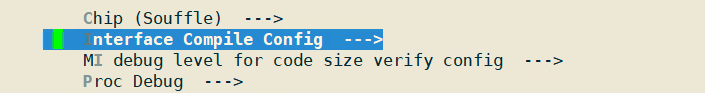
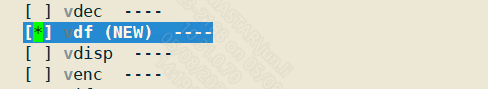
-
Select the VDF module with the space key and recompile the entire image.
1.7.2 API Call
The interface call sequence of the VDF module is as follows:
Figure 1-2: Function Call Process of the VDF Channel
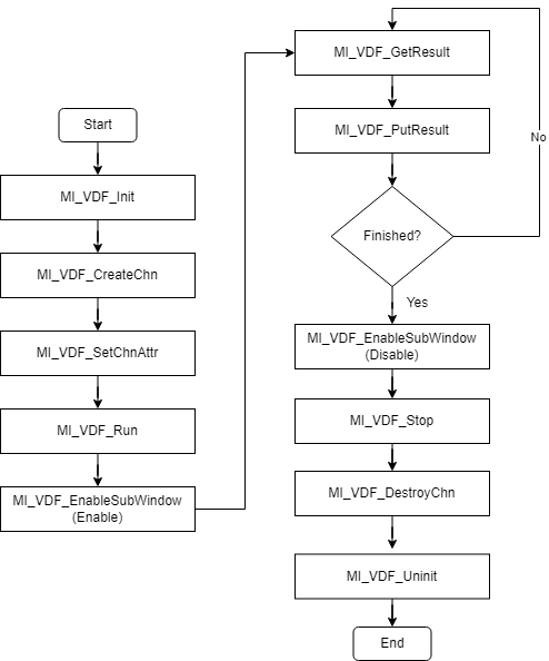
The above figure is the call process of opening a VDF, but VDF can support multiple channels, and each channel can be set to one of MD/OD/VG working modes.
Each VDF channel must be controlled by itself to call MI_VDF_CreateChn, MI_VDF_SetChnAttr, MI_VDF_EnableSubWindow, MI_VDF_GetResult, MI_VDF_PutResult, MI_VDF_DestroyChn independently.
1.8. Example Introduction
1.8.1 vdf-related code
Here, MD is used as an example for illustration. For VG, the interface call sequence can refer to Figure 1-1 in section 1.7.2 for setting up VDF. The following provides an example process for multiple channels. Two VDF channels are enabled, with channel 0 set to MD mode and channel 1 set to OD mode. This example uses motion detection for demonstration and can be followed according to the steps below.
-
Set MD's static/dynamic parameters ---> Create channel ---> Enable channel
-
User layer obtains computation results ---> Return result buffer
-
Unregister channel
1.8.1.1 Build vdf module
#include <threads.h>
#include <stdio.h>
#include <stdlib.h>
#include <string.h>
#include <unistd.h>
#include <assert.h>
#include <signal.h>

#include <mi_sys_datatype.h>
#include <mi_sys.h>
#include <mi_vdf_datatype.h>
#include <mi_vdf.h>

MI_VDF_Init();

/* Turn on the MD mode master switch */
MI_VDF_Run(E_MI_VDF_WORK_MODE_MD);

MI_VDF_CHANNEL vdfChn = 0;
MI_VDF_ChnAttr_t stAttr;
MI_VDF_MdAttr_t stMdAttr;
int width = 640, height = 360;

/* Set static parameters */
stMdAttr.stMdStaticParamsIn.width = width;
stMdAttr.stMdStaticParamsIn.height = height;
stMdAttr.stMdStaticParamsIn.roi_md.num = 4;
stMdAttr.stMdStaticParamsIn.md_alg_mode = MDALG_MODE_SAD;
stMdAttr.stMdStaticParamsIn.mb_size = MDMB_MODE_MB_8x8;
stMdAttr.stMdStaticParamsIn.sad_out_ctrl = MDSAD_OUT_CTRL_8BIT_SAD;
stMdAttr.stMdStaticParamsIn.color = 1;

/* Effective Monitoring Range Coordinates */
stMdAttr.stMdStaticParamsIn.roi_md.pnt[0].x = 0;
stMdAttr.stMdStaticParamsIn.roi_md.pnt[0].y = 0;
stMdAttr.stMdStaticParamsIn.roi_md.pnt[1].x = width - 1;
stMdAttr.stMdStaticParamsIn.roi_md.pnt[1].y = 0;
stMdAttr.stMdStaticParamsIn.roi_md.pnt[2].x = width - 1;
stMdAttr.stMdStaticParamsIn.roi_md.pnt[2].y = height - 1;
stMdAttr.stMdStaticParamsIn.roi_md.pnt[3].x = 0;
stMdAttr.stMdStaticParamsIn.roi_md.pnt[3].y = height - 1;

/* Set dynamic parameters */
stMdAttr.stMdDynamicParamsIn.sensitivity = 80;
stMdAttr.stMdDynamicParamsIn.learn_rate = 2000;
stMdAttr.stMdDynamicParamsIn.md_thr = 16;
stMdAttr.stMdDynamicParamsIn.obj_num_max = 0;

stMdAttr.u8MdBufCnt = 4;
stMdAttr.u8VDFIntvl = 1;
stMdAttr.ccl_ctrl.u16InitAreaThr = 8;
stMdAttr.ccl_ctrl.u16Step = 2;
stMdAttr.u8Enable      = 1

stAttr.stMdAttr = stMdAttr;
stAttr.enWorkMode = E_MI_VDF_WORK_MODE_MD;

/* Create a channel, this interface will set the relevant static and dynamic parameters */
ret = MI_VDF_CreateChn(vdfChn, &stAttr);
if (ret != MI_SUCCESS)
{
    ST_DBG("MI_VDF_CreateChn ret=0x%x\n", ret);
}

/* enable this channel, start working normally*/
MI_VDF_EnableSubWindow(vdfChn, 0, 0, 1);
1.8.1.2 Get the calculation result
/* Obtain monitoring results */
MI_MD_static_param_t *pstMdStaticParamsIn = NULL;
MI_U8 *stSadDataArry = NULL;
MI_U8 *fgDataArry = NULL;
int width,height,col,row;
int buffer_size;

pstMdStaticParamsIn = (MI_MD_static_param_t *)&stAttr.stMdAttr.stMdStaticParamsIn;
width = pstMdStaticParamsIn->width;
height = pstMdStaticParamsIn->height;

if (pstMdStaticParamsIn->mb_size == MDMB_MODE_MB_4x4)
{
    col = width >> 2;
    row = height >> 2;
}
else if (pstMdStaticParamsIn->mb_size == MDMB_MODE_MB_8x8)
{
    col = width >> 3;    // 40
    row = height >> 3;    // 22
}
else    // MDMB_MODE_MB_16x16
{
    col = width >> 4;
    row = height >> 4;
}

buffer_size = col * row;    // MDSAD_OUT_CTRL_8BIT_SAD
if (pstMdStaticParamsIn->sad_out_ctrl == MDSAD_OUT_CTRL_16BIT_SAD)
{
    buffer_size *= 2;
}
if (stAttr.stMdAttr.stMdStaticParamsIn.md_alg_mode == MDALG_MODE_SAD)
{
    stSadDataArry = (MI_U8 *)malloc(buffer_size + 1);
    if (NULL == stSadDataArry)
    {
        ST_ERR("can not malloc stSadDataArry buf.\n");
        goto exit;
    }
    memset(stSadDataArry, 0x0, buffer_size + 1);
    ST_DBG("enter md task loop, md model is %d\n", MDALG_MODE_SAD);
}
if (stAttr.stMdAttr.stMdStaticParamsIn.md_alg_mode == MDALG_MODE_FG)
{
    fgDataArry = (MI_U8 *)malloc(col * row + 1);
    if (NULL == fgDataArry)
    {
        ST_ERR("can not malloc fgDataArry buf.\n");
        goto exit;
    }
    memset(fgDataArry, 0x0, col * row + 1);
    ST_DBG("enter md task loop, md model is %d\n", MDALG_MODE_FG);
}

MI_VDF_Result_t stVdfResult = { (MI_VDF_WorkMode_e)0 };
MI_U8 *pu8MdRstData = NULL;

/* Get the output buffer, which stores the calculation results */
ret = MI_VDF_GetResult(vdfChn, &stVdfResult, 0);
if (MI_SUCCESS == ret)
{
  if (1 == stVdfResult.stMdResult.u8Enable)
  {
      if (stVdfResult.stMdResult.pstMdResultSad != NULL &&
              stVdfResult.stMdResult.pstMdResultSad->enOutCtrl == MDSAD_OUT_CTRL_8BIT_SAD &&
              stAttr.stMdAttr.stMdStaticParamsIn.md_alg_mode == MDALG_MODE_SAD)
      {
        pu8MdRstData = (MI_U8 *)stVdfResult.stMdResult.pstMdResultSad->paddr;
        memcpy(stSadDataArry, pu8MdRstData, buffer_size);
        sMdSADFlag = 1;
      }
      else if (stVdfResult.stMdResult.pstMdResultObj != NULL &&
                stAttr.stMdAttr.stMdStaticParamsIn.md_alg_mode == MDALG_MODE_FG)
      {
        // value = 0 or 255
        memcpy(fgDataArry, stVdfResult.stMdResult.pstMdResultStatus->paddr, col * row);
        sMdFGFlag = 1;
      }

      if (sMdSADFlag && stAttr.stMdAttr.stMdStaticParamsIn.md_alg_mode == MDALG_MODE_SAD)
      {
        /* Print the calculation results */
        printf("pu8MdRstData:===>\n");
        for (int i = 0; i < row; i++)
        {
            printf("===>");
            for (int j = 0; j < col; j++)
            {
                printf("%02d, ", stSadDataArry[i * col + j]);
            }
            printf("<===\n");
        }
        printf("<===\n");
      }

      if (sMdFGFlag && stAttr.stMdAttr.stMdStaticParamsIn.md_alg_mode == MDALG_MODE_FG)
      {
        /* Print the calculation results */
        printf("pu8MdRstData:===>\n");
        for (int i = 0; i < row; i++)
        {
            printf("===>");
            for (int j = 0; j < col; j++)
            {
                printf("%02d, ", fgDataArry[i * col + j]);
            }
            printf("<===\n");
        }
        printf("<===\n");
      }
  }

  /* Return output buffer */
  MI_VDF_PutResult(vdfChn, &stVdfResult);
}
1.8.1.3 Destruct vdf module
/* diable this channel, start working normally*/
MI_VDF_EnableSubWindow(vdfChn, 0, 0, 0);

/* Turn off the MD mode master switch */
MI_VDF_Stop(E_MI_VDF_WORK_MODE_MD);

/* Destroy this channel */
MI_VDF_DestroyChn(vdfChn);
MI_VDF_Uninit();
2. API REFERENCE
2.1. VDF API List
| API Name | Function |
|---|---|
| MI_VDF_Init | Initialize MI_VDF module |
| MI_VDF_Uninit | Un-initialize MI_VDF Module |
| MI_VDF_CreateChn | Create channel for MD/OD/VG |
| MI_VDF_DestroyChn | Destroy created channel MD/OD/VG |
| MI_VDF_SetChnAttr | Set channel (MD/OD/VG) attribute |
| MI_VDF_GetChnAttr | Get attribute from channel (MD/OD/VG) |
| MI_VDF_EnableSubWindow | Enable sub windows for (MD/OD/VG) channel |
| MI_VDF_Run | Start detection for channel (MD/OD/VG) |
| MI_VDF_Stop | Stop detection for channel (MD/OD/VG) |
| MI_VDF_GetResult | Get detection result from channel (MD/OD/VG) |
| MI_VDF_PutResult | Release detection result from channel (MD/OD/VG) |
| MI_VDF_GetLibVersion | Get version number of the specified channel (MD/OD/VG) |
| MI_VDF_GetDebugInfo | Get debug info of the specified channel. (Only VG support this feature) |
2.2. VDF API Description
2.2.1. MI_VDF_Init
-
Functions
Initialize the VDF module.
-
Syntax
MI_S32 MI_VDF_Init(void); -
Return Value
-
Zero: Successful
-
Non-zero: Failed, see error code for details
-
-
Dependency
-
Header File: mi_sys.h, mi_md.h, mi_od.h, mi_vg.h, mi_vdf.h
-
Library File: libOD_LINUX.a, libMD_LINUX.a, libVG_LINUX.a, libmi_vdf.a
-
-
Note
-
MI_VDF_Init needs to be called after calling MI_SYS_Init.
-
It is not possible to call MI_VDF_Init repeatedly.
-
-
Related APIs
2.2.2. MI_VDF_Uninit
-
Functions
Destructing the MI_VDF system, before calling MI_VDF_Uninit , you need to ensure that the created VDF channels have been disabled and the video detection results of all channels are released
-
Syntax
MI_S32 MI_VDF_Uninit (void); -
Return Value
-
Zero: Successful
-
Non-zero: Failed, see error code for details
-
-
Dependency
-
Header File: mi_sys.h, mi_md.h, mi_od.h, mi_vg.h, mi_vdf.h
-
Library File: libOD_LINUX.a, libMD_LINUX.a, libVG_LINUX.a, libmi_vdf.a
-
-
Note
-
Before the MI_VDF_Uninit call, you need to ensure that all created VDF channels are in the disable state.
-
Before the MI_VDF_Uninit call, you need to ensure that the results of all created VDF channels are released.
-
-
Example
See MI_VDF_Init For example.
2.2.3. MI_VDF_CreateChn
-
Functions
Create a video detection (MD/OD/VG) channel.
-
Syntax
MI_S32 MI_VDF_CreateChn(MI_VDF_CHANNEL VdfChn, const MI_VDF_ChnAttr_t* pstAttr); -
Parameters
Parameter Name Description Input/Output VdfChn Specify the video detection channel number. Input pstAttr Set the video channel property value. Input -
Return Value
-
Zero: Successful
-
Non-zero: Failed, see error code for details
-
-
Dependency
-
Header File: mi_sys.h, mi_md.h, mi_od.h, mi_vg.h, mi_vdf.h
-
Library File: libOD_LINUX.a, libMD_LINUX.a, libVG_LINUX.a, libmi_vdf.a
-
-
Note
-
VdfChn cannot be specified repeatedly.
-
VdfChn valid range: 0 <= VdfCh < MI_VDF_CHANNEL_MAX.
-
MI_VDF_CHANNEL_MAX is defined in header file mi_vdf_datatype.h.
-
-
Related APIs
2.2.4. MI_VDF_DestroyChn
-
Functions
Destroy the created video detection channel.
-
Syntax
MI_S32 MI_VDF_DestroyChn(MI_VDF_CHANNEL VdfChn); -
Parameters
Parameter Name Description Input/Output VdfChn The video detection channel number that has been created. Input -
Return Value
-
Zero: Successful
-
Non-zero: Failed, see error code for details
-
-
Dependency
-
Header File: mi_sys.h, mi_md.h, mi_od.h, mi_vg.h, mi_vdf.h
-
Library File: libOD_LINUX.a, libMD_LINUX.a, libVG_LINUX.a, libmi_vdf.a
-
-
Note
-
VdfChn cannot be specified repeatedly.
-
VdfChn valid range: 0 <= VdfCh < MI_VDF_CHANNEL_MAX.
-
MI_VDF_CHANNEL_MAX is defined in header file mi_vdf_datatype.h.
-
2.2.5. MI_VDF_SetChnAttr
-
Functions
Set the video detection channel attributes.
-
Syntax
MI_S32 MI_VDF_SetChnAttr(MI_VDF_CHANNEL VdfChn, const MI_VDF_ChnAttr_t* pstAttr); -
Parameters
Parameter Name Description Input/Output VdfChn The video detection channel number that has been created. Input pstAttr Source port configuration information data structure pointer. Input -
Return Value
-
Zero: Successful
-
Non-zero: Failed, see error code for details
-
-
Dependency
-
Header File: mi_sys.h, mi_md.h, mi_od.h, mi_vg.h, mi_vdf.h
-
Library File: libOD_LINUX.a, libMD_LINUX.a, libVG_LINUX.a, libmi_vdf.a
-
-
Note
-
VdfChn must be a video detection channel that has been created.
-
This interface specifies the value of the dynamic attribute of the video detection channel (stMdAttr.stMdDynamicParamsIn / stMdAttr.stOdDynamicParamsIn/ stMdAttr.stVgAttr in MI_VDF_ChnAttr_t).
-
2.2.6. MI_VDF_GetChnAttr
-
Functions
Get the video detection channel attributes.
-
Syntax
MI_S32 MI_VDF_GetChnAttr(MI_VDF_CHANNEL VdfChn, MI_VDF_ChnAttr_t* pstAttr); -
Parameters
Parameter Name Description Input/Output VdfChn The video detection channel number that has been created. Input pstAttr Used to save the returned video detection channel attribute value Output -
Return Value
-
Zero: Successful
-
Non-zero: Failed, see error code for details
-
-
Dependency
-
Header File: mi_sys.h, mi_md.h, mi_od.h, mi_vg.h, mi_vdf.h
-
Library File: libOD_LINUX.a, libMD_LINUX.a, libVG_LINUX.a, libmi_vdf.a
-
2.2.7. MI_VDF_EnableSubWindow
-
Functions
Enable/disable the specified video detection channel sub-window.
-
Syntax
MI_S32 MI_VDF_EnableSubWindow(MI_VDF_CHANNEL VdfChn, MI_U8 u8Col, MI_U8 u8Row, MI_U8 u8Enable); -
Parameters
Parameter Name Description Input/Output VdfChn The video detection channel number that has been created. Input u8Col The row address of the sub window (reserved, not used) Input u8Row Sub-window column address (reserved, not used) Input u8Enable Sub-window enable control flag Input -
Return Value
-
Zero: Successful
-
Non-zero: Failed, see error code for details
-
-
Dependency
-
Header File: Mi_sys.h, mi_md.h, mi_od.h, mi_vg.h, mi_vdf.h
-
Library File: libOD_LINUX.a, libMD_LINUX.a, libVG_LINUX.a, libmi_vdf.a
-
-
Note
-
u8Col and u8Row are reserved for upward compatibility of API interface, and have no practical effect. You can set them to 0 directly.
-
There are currently three working modes supported: MD, OD, and VG.
-
The MI_VDF_Run/MI_VDF_Stop function acts on all video detection channels in the same working mode (MD/OD/VG), and the MI_VDF_EnableSubWindow function acts on a single video detection channel. To run a single VdfChn, call MI_VDF_Run function and MI_VDF_EnableSubWindow (u8Enable = True). Note that when you call MI_VDF_Stop function or MI_VDF_EnableSubWindow (u8Enable = False), the video detection channel will stop.
-
2.2.8. MI_VDF_Run
-
Functions
Start running video detection working mode.
-
Syntax
MI_S32 MI_VDF_Run(MI_VDF_WorkMode_e enWorkMode); -
Parameters
Parameter Name Description Input/Output enWorkMode Video detection (MD/OD/VG) working mode. Input -
Return Value
-
Zero: Successful
-
Non-zero: Failed, see error code for details
-
-
Dependency
-
Header File: mi_sys.h, mi_md.h, mi_od.h, mi_vg.h, mi_vdf.h
-
Library File: libOD_LINUX.a, libMD_LINUX.a, libVG_LINUX.a, libmi_vdf.a
-
-
Note
-
The work mode only supports MD/OD/VG.
-
MI_VDF_Run/MI_VDF_Stop function acts on all video detection channels in the same working mode (MD/OD/VG).
-
2.2.9. MI_VDF_Stop
-
Functions
Stop running video detection (MD/OD/VG) working mode.
-
Syntax
MI_S32 MI_VDF_Stop(MI_VDF_WorkMode_e enWorkMode); -
Parameters
Parameter Name Description Input/Output enWorkMode Video detection (MD/OD/VG) working mode. Input -
Return Value
-
Zero: Successful
-
Non-zero: Failed, see error code for details
-
-
Dependency
-
Header File: mi_sys.h, mi_md.h, mi_od.h, mi_vg.h, mi_vdf.h
-
Library File: libOD_LINUX.a, libMD_LINUX.a, libVG_LINUX.a, libmi_vdf.a
-
-
Note
-
The work mode only supports MD/OD/VG.
-
MI_VDF_Run/MI_VDF_Stop function acts on all video detection channels in the same working mode (MD/OD/VG).
-
2.2.10. MI_VDF_GetResult
-
Functions
Get the detection result of the specified video detection channel.
-
Syntax
MI_S32 MI_VDF_GetResult(MI_VDF_CHANNEL VdfChn, MI_VDF_Result_t* pstVdfResult, MI_S32 s32MilliSec); -
Parameters
Parameter Name Description Input/Output VdfChn The video detection channel number that has been created. Input pstVdfResult Save the returned video detection results Output s32MilliSec Input time parameter**(reserved, not used currently)** Input -
Return Value
-
Zero: Successful
-
Non-zero: Failed, see error code for details
-
-
Dependency
-
Header File: mi_sys.h, mi_md.h, mi_od.h, mi_vg.h, mi_vdf.h
-
Library File: libOD_LINUX.a, libMD_LINUX.a, libVG_LINUX.a, libmi_vdf.a
-
-
Note
-
VdfChn must be a video detection channel that has been created.
-
s32MilliSec is reserved for upward compatibility of API interface, and has no practical effect. You can set it to 0 directly.
-
The pointer used to save the returned result cannot be Null.
-
2.2.11. MI_VDF_PutResult
-
Functions
Release the detection result of the specified video detection channel.
-
Syntax
MI_S32 MI_VDF_PutResult(MI_VDF_CHANNEL VdfChn, MI_VDF_Result_t* pstVdfResult); -
Parameters
Parameter Name Description Input/Output VdfChn The video detection channel number that has been created. Input pstVdfResult Specify the result parameters that need to release the video channel Input -
Return Value
-
Zero: Successful
-
Non-zero: Failed, see error code for details
-
-
Dependency
-
Header File: mi_sys.h, mi_md.h, mi_od.h, mi_vg.h, mi_vdf.h
-
Library File: libOD_LINUX.a, libMD_LINUX.a, libVG_LINUX.a, libmi_vdf.a
-
-
Note
VdfChn must be a video detection channel that has been created.
2.2.12. MI_VDF_GetLibVersion
-
Functions
Obtain the MD/OD/VG library version number.
-
Syntax
MI_S32 MI_VDF_GetLibVersion(MI_VDF_CHANNEL VdfChn, MI_U32* u32VDFVersion); -
Parameters
Parameter Name Description Input/Output VdfChn The video detection channel number that has been created. Input u32VDFVersion Pointer for saving the version number (cannot be Null). Output -
Return Value
-
Zero: Successful
-
Non-zero: Failed, see error code for details
-
-
Dependency
-
Header File: mi_sys.h, mi_md.h, mi_od.h, mi_vg.h, mi_vdf.h
-
Library File: libOD_LINUX.a, libMD_LINUX.a, libVG_LINUX.a, libmi_vdf.a
-
2.2.13. MI_VDF_GetDebugInfo
-
Functions
Get the MD/OD/VG debug info.
-
Syntax
MI_S32 MI_VDF_GetDebugInfo(MI_VDF_CHANNEL VdfChn, MI_VDF_DebugInfo_t *pstDebugInfo); -
Parameters
Parameter Name Description Input/Output VdfChn The video detection channel number that has been created. Input u32VDFVersion Pointer for saving the VDF debug info (cannot be Null) Output -
Return Value
-
Zero: Successful
-
Non-zero: Failed, see error code for details
-
-
Dependency
-
Header File: mi_sys.h, mi_md.h, mi_od.h, mi_vg.h, mi_vdf.h
-
Library File: libOD_LINUX.a, libMD_LINUX.a, libVG_LINUX.a, libmi_vdf.a
-
-
Note
Only supports VG mode.
3. DATA TYPE
3.1. VDF Structure Description
| Data structure | Definition |
|---|---|
| MI_VDF_WorkMode_e | An enumerated type that defines the working mode of VDF |
| MI_VDF_Color_e | Define the enumerated type of the video detection channel input source |
| MI_VDF_ODWindow_e | Enumerated type of the number of child windows of the screen when defining OD |
| MI_MD_Result_t | Structure that defines the MD result |
| MI_OD_Result_t | Structure that defines the OD result |
| MI_VG_Result_t | Structure that defines the VG result |
| MI_VDF_Result_t | Structure that defines the corresponding result of the VDF working mode |
| MI_VDF_MdAttr_t | Structure that defines MD channel attributes |
| MI_VDF_OdAttr_t | Structure that defines OD channel attributes |
| MI_VDF_VgAttr_t | Structure that defines VG channel attributes |
| MI_VDF_ChnAttr_t | Structure that defines the channel's working mode properties |
| MDRST_STATUS_t | Structure that defines a motion detection result of a detection sub-window region |
| MI_MD_ResultSize_t | Structure that defines the length of the MD result |
3.1.1. MI_VDF_WorkMode_e
-
Description
Define VDF work mode enumeration type.
-
Definition
typedef enum { E_MI_VDF_WORK_MODE_MD = 0, E_MI_VDF_WORK_MODE_OD, E_MI_VDF_WORK_MODE_VG, E_MI_VDF_WORK_MODE_MAX }MI_VDF_WorkMode_e; -
Members
Member Name Description E_MI_VDF_WORK_MODE_MD MD working mode E_MI_VDF_WORK_MODE_OD OD working mode E_MI_VDF_WORK_MODE_VG VG working mode E_MI_VDF_WORK_MODE_MAX Error code identification of working mode
3.1.2. MI_VDF_Color_e
-
Description
Define the enumerated type of the video detection channel input source
-
Definition
typedef enum { E_MI_VDF_COLOR_Y = 1, E_MI_VDF_COLOR_MAX } MI_VDF_Color_e; -
Members
Member Name Description E_MI_VDF_COLOR_Y Correct identification of the input source type of the video detection channel E_MI_VDF_COLOR_MAX Video detection channel input source type error code identification
3.1.3. MI_VDF_ODWindow_e
-
Description
Enumerated type of the number of child windows of the screen when defining OD
-
Definition
typedef enum { E_MI_VDF_ODWINDOW_1X1 = 0, E_MI_VDF_ODWINDOW_2X2, E_MI_VDF_ODWINDOW_3X3, E_MI_VDF_ODWINDOW_MAX } MI_VDF_ODWindow_e; -
Members
Member Name Description E_MI_VDF_ODWINDOW_1X1 The OD screen is divided into 1 sub-window E_MI_VDF_ODWINDOW_2X2 The OD screen is divided into 2x2 sub-windows E_MI_VDF_ODWINDOW_3X3 The OD screen is divided into 3x3 sub-windows E_MI_VDF_ODWINDOW_MAX Error code identification of the number of OD screen sub-windows
3.1.4. MI_MD_Result_t
-
Description
A structure that defines the MD result.
-
Definition
typedef struct MI_MD_Result_s { MI_U64 u64Pts; //The PTS of Image MI_U8 u8Enable; // =1 indicates that the result value is valid MI_MD_ResultSize_t stSubResultSize; MDRST_STATUS_t* pstMdResultStatus; //The MD result of Status MDSAD_DATA_t* pstMdResultSad; //The MD result of SAD MDOBJ_DATA_t* pstMdResultObj; //The MD result of Obj }MI_MD_Result_t; -
Members
Member Name Description u64Pts Image display timestamp u8Enable Indicates whether the channel is enabled u8Reading Indicates that the result is being read by the application layer stSubResultSize Describe the Size of the Sad、Obj and ReasultStauts substructures returned by the MD pstMdResultStatus Describe whether motion is detected in each area of the MD, output in MB, 0-block does not detect motion, and 255-block detects motion pstMdResultSad Describe the Sad value of the MD, For example, if the input image is 640*360 and MB:8x8, (640/8)x(360/8)=80x45 SAD values will be obtained pstMdResultObj Describe the CCL value of MD, and the result of the connectivity operation is in units of objects
3.1.5. MI_OD_Result_t
-
Description
The structure that defines the OD result.
-
Definition
typedef struct MI_OD_Result_s { MI_U8 u8Enable; MI_U8 u8WideDiv; //The number of divisions of window in horizontal direction MI_U8 u8HightDiv; //The number of divisions of window in vertical direction MI_U8 u8DataLen; //OD detect result readable size MI_U64 u64Pts; //The PTS of Image MI_S8 u8RgnAlarm[3][3]; //The OD result of the sub-window MI_S8 s8OdStatus; //The OD detect status }MI_OD_Result_t; -
Members
Member name description u8Enable Indicates whether the channel is enabled u8WideDiv Get the number of windows in the horizontal direction of the OD u8HightD iv Get the number of windows in the vertical direction of the OD u8DataLen Set the readable size of the OD test results u64Pts Image display time u8RgnAlarm[3][3] OD sub window information result
0: The window is not blocked
1: The window is blocked
2: Insufficient window feature
-1: Fails8OdStatus 1. s8OdStatus = 0: No od detected
2. s8OdStatus = 1: Od detected
3. s8OdStatus = -1: Run od error -
Note
If the user needs to obtain the value of s8OdStatus, it can be judged by the status value 0 or 1. When it is -1, it means that OD has failed to run, and MI_VDF_GetResult failed, so that the value of s8OdStatus cannot be obtained.
3.1.6. MI_VG_Result_t
-
Description
he structure that defines the VG result.
-
Definition
typedef struct _MI_VgResult_t { int32_t alarm[MAX_NUMBER]; int32_t alarm_cnt; MI_VgBoundingBox_t bounding_box[20]; } MI_VgResult_t; -
Members
Member Name Description alarm Describe the test results of VG #define MAX_NUMBER 4 alarm_cnt Describe the number of VG alerts bounding_box Describe the object information that triggered the VG alarm
3.1.7. MI_VDF_Result_t
-
Description
A structure that defines the result of the VDF working mode.
-
Definition
typedef struct MI_VDF_Result_s { MI_VDF_WorkMode_e enWorkMode; VDF_RESULT_HANDLE handle; union { MI_MD_Result_t stMdResult; MI_OD_Result_t stOdResult; MI_VG_Result_t stVgResult; }; }MI_VDF_Result_t; -
Members
Member name description enWorkMode VDF working mode (MD/OD/VG) Handle Save result handle stMdResult Structure describing the MD result stOdResult Structure describing the OD result stVgResult Structure describing the VG result
3.1.8. MI_VDF_MdAttr_t
-
Description
Structure that defines MD channel properties
-
Definition
typedef struct MI_VDF_MdAttr_s { MI_U8 u8Enable; MI_U8 u8MdBufCnt; MI_U8 u8VDFIntvl; MI_U32 u32RstBufSize; MI_MD_ResultSize_t stSubResultSize; MDCCL_ctrl_t ccl_ctrl; MI_MD_static_param_t stMdStaticParamsIn; MI_MD_param_t stMdDynamicParamsIn; }MI_VDF_MdAttr_t; -
Members
Member name description u8Enable Indicates whether the channel is enabled u8MdBufCnt Set the number of MD results that can be cached MD result cache number range: [1, 8 ] static attribute u8VDFIntvl Detection interval value range: [0, 29] , in frames, dynamic attribute u32RstBufSize The total size of the MD return results stSubResultSize MD returns the result of each substructure (Sad value, CCL value, ResultStatus) size Ccl_ctrl c cl _ctrl property setting stMdStaticParamsIn MD static attribute parameter setting stMdDynamicParamsIn MD dynamic attribute parameter setting
3.1.9. MI_VDF_OdAttr_t
-
Description
Structure that defines OD channel attributes
-
Definition
typedef struct MI_VDF_OdAttr_s { MI_U8 u8Enable; MI_U8 u8OdBufCnt; MI_U8 u8VDFIntvl; MI_U32 u32RstBufSize; MI_OD_static_param_t stOdStaticParamsIn; MI_OD_param_t stOdDynamicParamsIn; }MI_VDF_OdAttr_t; -
Members
Member name description u8Enable Indicates whether the channel is enabled u8OdBufCnt OD result cached number range: [1, 16] static attribute u8VDFIntvl Detection interval value range: [0, 29] , in frames, dynamic attribute u32RstBufSize The total size of the OD return results stOdDynamicParamsIn O D dynamic attribute parameter setting stOdStaticParamsIn O D static attribute parameter setting
3.1.10. MI_VDF_VgAttr_t
-
Description
Structure that defines VG channel properties
-
Definition
typedef struct MI_VDF_VgAttr_s { MI_U8 u8Enable; MI_U8 u8VgBufCnt; MI_U8 u8VDFIntvl; MI_U32 u32RstBufSize; MI_U16 width; MI_U16 height; MI_U16 stride; float object_size_thd; uint8_t indoor; uint8_t function_state; uint16_t line_number; MI_VgLine_t line[4]; MI_VgRegion_t vg_region; MI_VgSet_t stVgParamsIn; } MI_VDF_VgAttr_t; -
Members
Member name description u8Enable Indicates whether the channel is enabled u8VgBufCnt VG result buffered number range: [1, 8 ] static attribute u8VDFIntvl Detection interval value range: [0, 29] , in frames, dynamic attribute u32RstBufSize The total size of the result returned by the VG Width Image width Height Image height Stride Image of stride Object_size_thd Decided to filter out the percentage of objects in the area of interest (If object_size_thd = 1 indicates that the object area is less than one percent of the region of interest in the image frame, it will be ignored.) Indoor Whether the camera is mounted indoors or outdoors, 1- indoor, 0- outdoor Function_state Set a detection mode for virtual line segments and regional intrusions: 1) VG_VIRTUAL_GATE, indicates that the mode is a virtual line segment 2) VG_REGION_INVASION, indicates that the pattern is a zone intrusion Line_number Set the number of virtual segments, range: [ 1-4 ] Line[4] Show the structure of the virtual line, a maximum of four may be provided Vg_region Related parameters indicating regional invasion stVgParamsIn Vg attribute parameter structure, no need to set ,returned by API
3.1.11. MI_VDF_ChnAttr_t
-
Description
A structure that defines the channel's working mode properties.
-
Definition
typedef struct MI_VDF_ChnAttr_s { MI_VDF_WorkMode_e enWorkMode; union { MI_VDF_MdAttr_t stMdAttr; MI_VDF_OdAttr_t stOdAttr; MI_VDF_VgAttr_t stVgAttr; }; -
Members
Member name description enWorkMode Working mode (motion detection , occlusion detection , electronic fence) static properties stMdAttr Motion detection attribute stOdAttr Occlusion detection attribute stVgAttr Electronic fence properties
3.1.12. MDRST_STATUS_t
-
Description
A structure defining a motion detection result of a detection sub-window region
-
Definition
typedef struct MDRST_STATUS_s { MI_U8 *paddr; } MDRST_STATUS_t; -
Members
Member Name Description paddr Directed motion detection state buf, each area occupies 1byte 0- block does not detect motion, 255- block detects motion
3.1.13. MI_MD_ResultSize_t
-
Description
Structure that defines the length of the MD result
-
Definition
typedef struct MI_MD_ResultSize_s { MI_U32 u32RstStatusLen; MI_U32 u32RstSadLen; MI_U32 u32RstObjLen; }MI_MD_ResultSize_t; -
Members
Member Name Description u32RstStatusLen Describe the length of the MD detected motion state value u32RstSadLen Describe the length of the Sad value of MD u32RstObjLen Describe the length of the CCL value of MD
3.3. MD Structure Description
| Data Type | Definition |
|---|---|
| MDMB_MODE_e | Macro block size of enumeration value |
| MDSAD_OUT_CTRL_e | Enumeration value of the SAD output format |
| MDALG_MODE_e | The operation mode enumeration value of the CCL connected region can be used for CCL operation according to the foreground result or the SAD result. |
| MDCCL_ctrl_t | Parameter structure that controls CCL operation |
| MDPreproc_ctrl_t | Contol Parameter for MI_MD_Preproc running. This feature is not currently supported by VDF |
| MDblock_info_t | Define the ROI coordinate structure of a block. |
| MDPoint_t | Coordinate structure |
| MDROI_t | MD detection area structure |
| MDSAD_DATA_t | The structure of the MI_MD_ComputeImageSAD function output. |
| MDOBJ_t | Define the information of the connected area: the area and the coordinate position of the smallest bounding rectangle |
| MDOBJ_DATA_t | Structure of CCL output |
| MI_MD_IMG_t | The image source structure of motion detection is divided into physical and virtual memory address pointers. |
| MI_MD_IMG64_t | The image source structure of motion detection is divided into 64 bit physical memory address and virtual memory address pointer. |
| MI_MD_static_param_t | MD static parameter setting structure |
| MI_MD_param_t | MD dynamic parameter setting structure |
3.2.1. MDMB_MODE_e
-
Description
The enumerated size of Micro-block.
-
Definition
typedef enum MDMB_MODE_E { MDMB_MODE_MB_4x4 = 0x0, MDMB_MODE_MB_8x8 = 0x1, MDMB_MODE_MB_16x16 = 0x2, MDMB_MODE_BUTT } MDMB_MODE_e; -
Members
Member Name Description MDMB_MODE_MB_4x4 Use 4x4 Micro-block MDMB_MODE_MB_8x8 Use 8x8 Micro-block MDMB_MODE_MB_16x16 Use 16x16 Micro-block
3.2.2. MDSAD_OUT_CTRL_e
-
Description
The enumeration value of the SAD output format.
-
Definition
typedef enum MDSAD_OUT_CTRL_E { MDSAD_OUT_CTRL_16BIT_SAD = 0x0, MDSAD_OUT_CTRL_8BIT_SAD = 0x1, MDSAD_OUT_CTRL_BUTT } MDSAD_OUT_CTRL_e; -
Members
Member Name Description MDSAD_OUT_CTRL_16BIT_SAD 16 bit Output MDSAD_OUT_CTRL_8BIT_SAD 8 bit Output
3.2.3. MDALG_MODE_e
-
Description
The operation mode enumeration value of the CCL connected region can be CCL calculated according to the foreground result or the SAD result
-
Definition
typedef enum MDALG_MODE_E { MDALG_MODE_FG = 0x0, MDALG_MODE_SAD = 0x1, MDALG_MODE_FRAMEDIFF = 0x2, MDALG_MODE_BUTT } MDALG_MODE_e; -
Members
Member Name Description MDALG_MODE_FG Foreground mode MDALG_MODE_SAD SAD Mode MDALG_MODE_FRAMEDIFF FrameDifference Mode -
Tips
The foreground mode (FG) is implemented by software, while the SAD and Frame Diff modes are supported by hardware operators, and the operators need to be aligned with the input image's stride and width of 16 pixels, and height of 2 pixels.
3.2.4. MDCCL_ctrl_t
-
Description
Control the parameter structure of the CCL execution.
-
Definition
typedef struct MDCCL_ctrl_s { uint16_t u16InitAreaThr; uint16_t u16Step; } MDCCL_ctrl_t; -
Members
Member Name Description u16InitAreaThr Area threshold(This value is not necessarily useful,but it recommended value is 8) u16Step Increased value of each threshold(This value is not necessarily useful,but it recommended value is 2)
3.2.5. MDPreproc_ctrl_t
-
Description
Contol Parameter for MI_MD_Preproc running. This feature is not currently supported by VDF
-
Definition
typedef struct MDPreproc_ctrl_s { uint16_t u16Md_rgn_size; uint16_t u16Align; } MDPreproc_ctrl_t; -
Members
Member Name Description u16Md_rgn_size The threshold value of the size range of the moving area. If it is less than this threshold, the area is not calculated as a dynamic area u16Align Align restriction corresponding to CNN model (HC/HD:32ss align, FD:64align)
3.2.6. MDblock_info_t
-
Description
Define the ROI coordinate structure of a block. This feature is not currently supported by VDF
-
Definition
typedef struct MDblock_info_s { uint16_t st_x; uint16_t st_y; uint16_t end_x; uint16_t end_y; } MDblock_info_t; -
Members
Member Name Description st_x Upper left X coordinate of ROI st_y Upper left y coordinate of ROI end_x Lower right X coordinate of ROI end_y Lower right y coordinate of ROI
3.2.7. MDPoint_t
-
Description
Coordinate structure.
-
Definition
typedef struct MDPoint_s { uint16_t x; uint16_t y; } MDPoint_t; -
Members
Member Name Description x X Coordinate y Y Coordinate
3.2.8. MDROI_t
-
Description
MD detection area structure.
-
Definition
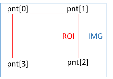
typedef struct MDROI_s { uint8_t num; MDPoint_t pnt[8]; } MDROI_t; -
Members
Member Name Description num MD detection area points, currently only supported to set to 4 points pnt[8] Four-point coordinates (must be set to rectangle) -
Note
It is required to be set to a rectangle and the four points have a preceding and backward constraint, num=4, starting from the upper left corner point, and setting the four points clockwise, as shown in the following figure
3.2.9. MDSAD_DATA_t
-
Description
The structure of the MI_MD_ComputeImageSAD function output.
-
Definition
typedef struct MDSAD_DATA_s { void *paddr; uint32_t stride; MDSAD_OUT_CTRL_e enOutCtrl; } MDSAD_DATA_t; -
Members
Member Name Description paddr Memory address pointer for storing SAD results stride Image stride enOutCtrl Enumeration value of the SAD output format
3.2.10. MDOBJ_t
-
Description
Define the information of the connected area: the area and the coordinate position of the smallest bounding rectangle.
-
Definition
typedef struct MDOBJ_s { uint32_t u32Area; uint16_t u16Left; uint16_t u16Right; uint16_t u16Top; uint16_t u16Bottom; } MDOBJ_t; -
Members
Member name description u32Area Total number of pixels in a single connected area u16Left The top left x coordinate of the smallest rectangle u16Right The lower right x coordinate of the smallest rectangle u16Top The upper left y coordinate of the smallest rectangle u16Bottom The upper left y coordinate of the smallest rectangle -
Note
For example: {3, 1, 2, 2, 3}, element 1 means that there are three pixels in a connected label, assuming that they are: (1,3), (2,2), (2,3). Element 2 represents the smallest value of x from these pixels, element 3 represents the maximum value of x from these pixels, and elements 4 and 5 take the smallest and maximum value of y from these pixels, respectively.
3.2.11. MDOBJ_DATA_t
-
Description
The structure of the MI_MD_CCL output.
-
Definition
typedef struct MDOBJ_DATA_s { uint8_t u8RegionNum; MDOBJ_t *astRegion; uint8_t indexofmaxobj; uint32_t areaofmaxobj; uint32_t areaoftotalobj; } MDOBJ_DATA_t; -
Members
Member name description u8RegionNum Number of connected areas. astRegion Information about the connected area: the area and the coordinate position of the smallest bounding rectangle. The maximum allowable number is 255. Indexofmaxobj Maximum area connected area index value. Areaofmaxobj Maximum area of connected area. Areaoftotalobj The area sum-up of all connected areas.
3.2.12. MI_MD_IMG_t
-
Description
The image source structure of motion detection is divided into physical and virtual memory address pointers.
-
Definition
typedef struct MI_MD_IMG_s { void *pu32PhyAddr; uint8_t *pu8VirAddr; } MI_MD_IMG_t; -
Members
Member Name Description pu32PhyAddr Physical memory address pointer, default is NULL pu8VirAddr Virtual memory address pointer
3.2.13. MI_MD_IMG64_t
-
Description
The image source structure of motion detection is divided into 64 bit physical memory address and virtual memory address pointer.
-
Definition
typedef struct MI_MD_IMG64_s { uint64_t u64PhyAddr; uint8_t *pu8VirAddr; } MI_MD_IMG64_t; -
Members
Member Name Description u64PhyAddr Physical memory address pu8VirAddr Virtual memory address pointer
3.2.14. MI_MD_static_param_t
-
Description
MD static parameter setting structure.
-
Definition
typedef struct MI_MD_static_param_s { uint16_t width; uint16_t height; uint8_t color; uint32_t stride; MDMB_MODE_e mb_size; MDSAD_OUT_CTRL_e sad_out_ctrl; MDROI_t roi_md; MDALG_MODE_e md_alg_mode; } MI_MD_static_param_t; -
Members
Member name description Width Input image width Height Input image is high Stride Input image of stride Color MD input image type. At present, MD only eats the Y portion, which is fixed to 1 and does not change mb_size Macro block size enumeration value Sad_out_ctrl Enumeration value of the SAD output format Roi_md MD detection area structure Md_alg_mode Operation mode enumeration value of CCL connected area
3.2.15. MI_MD_param_t
-
Description
MD dynamic parameter setting structure.
-
Definition
typedef struct MI_MD_param_s { uint8_t sensitivity; uint16_t learn_rate; uint32_t md_thr; uint32_t obj_num_max; uint8_t LSD_open; } MI_MD_param_t; -
Members
Member name description Sensitivity Algorithm sensitivity, range [10, 20, 30, ..... 100] , the larger the value, the more sensitive, the sensitivity of the input is not A multiple of 10 , when the feedback is calculated , there may be a value that is not originally entered , there will be +-1 deviation. Only for VG mode. Learn_rate There are different setting standards for different modes:
MDALG_MODE_FG : Unit is millisecond, range [1000-30000], used to control how long the front-end object stops moving before it is used as the background picture.
MDALG_MODE_SAD : Range [1, 255], background update weight ratio, recommended setting value: 128.
In FG, the time is described, and in the SAD, the weight is described, and the fast learning speed or heavy weight is easy to quickly disarm the alarm. For example, if an object enters the screen and is stationary, if it has a lot of weight or a fast learning speed, the object will be quickly learned to become the background, and then the alarm will be released. On the contrary, it will take a long time to release the alarm.Md_thr When calling MI_MD_CCL connected component mark operation, as the threshold value to determine the effective movement, there are different setting standards for different modes:
MDALG_MODE_FG : Set to percentage (%), range [0, 99], judge whether MB alarm threshold value, ex. if MB size 8 * 8, MD_ Thr = 50, if more than 32 pixels in MB are foreground, the MB is judged as valid.
MDALG_MODE_SAD : If MB size 8 * 8, MD_ Thr = 50, when the average pixel difference in MB exceeds 50, the MB is judged as valid.Obj_num_max CCL connected area number limit value. Not currently working LSD_open Decide whether to use MI_MD_LightSwitchDetect. The range is [0, 1]. If the LightSwitchDetect() function is called when LSD_open=0, it has no effect. Currently, VDF does not support this function
3.3. OD Structure Description
| Enumeration | |
|---|---|
| MI_OD_WIN_STATE | OD detection window results |
| ODColor_e | Type of OD data source input |
| ODWindow_e | Type of OD detection window |
| Structure | |
| ODPoint_t | Coordinate structure |
| ODROI_t | OD detection area structure |
| MI_OD_IMG_t | The source structure of the occlusion detection image is divided into physical and virtual memory address pointers. |
| MI_OD_IMG64_t | The source structure of the occlusion detection image is divided into 64 bit physical memory address and virtual memory address pointer. |
| MI_OD_static_param_t | OD static parameter setting structure |
| MI_OD_param_t | OD dynamic parameter setting structure |
3.3.1. MI_OD_WIN_STATE
-
Description
The result of the OD detection window.
-
Definition
typedef enum _MI_OD_WIN_STATE { MI_OD_WIN_STATE_NON_TAMPER = 0, MI_OD_WIN_STATE_TAMPER = 1, MI_OD_WIN_STATE_NO_FEATURE = 2, MI_OD_WIN_STATE_FAIL = -1, } MI_OD_WIN_STATE; -
Members
Member name description MI_OD_WIN_STATE_NON_TAMPER Window is not obscured MI_OD_WIN_STATE_TAMPER Window is occluded MI_OD_WIN_STATE_NO_FEATURE Insufficient window features MI_OD_WIN_STATE_FAIL failure
3.3.2. ODColor_e
-
Description
The type of OD data source input.
-
Definition
typedef enum { OD_Y = 1, OD_COLOR_MAX } ODColor_e; -
Members
Member Name Description OD_Y y component in the YUV data source OD_COLOR_MAX Enter the maximum value of the image type
3.3.3. ODWindow_e
-
Description
The type of OD detection window, the recommended value is OD_WINDOW_3X3 for testing.
-
Definition
typedef enum { OD_WINDOW_1X1 = 0, OD_WINDOW_2X2, OD_WINDOW_3X3, OD_WINDOW_MAX } ODWindow_e; -
Members
Member Name Description OD_WINDOW_1X1 1 window OD_WINDOW_2X2 4 windows OD_WINDOW_3X3 9 windows OD_WINDOW_MAX Maximum window type
3.3.4. ODPoint_t
-
Description
Coordinate structure.
-
Definition
typedef struct ODPoint_s { uint16_t x; uint16_t y; } ODPoint_t; -
Members
Member Name Description x X coordinate y Y coordinate
3.3.5. ODROI_t
-
Description
OD detection area structure.
-
Definition
typedef struct ODROI_s { uint8_t num; ODPoint_t pnt[8]; } ODROI_t; -
Members
Member Name Description num OD detection area points, currently only supported to set to 4 points pnt[8] Four-point coordinates (must be set to rectangle) -
Note
The requirement is set to a rectangle, num=4 , and the coordinates of the upper left corner are set clockwise in sequence, as shown in the figure.
3.3.6. MI_OD_IMG_t
-
Description
The source structure of the occlusion detection image is divided into physical and virtual memory address pointers.
-
Definition
typedef struct MI_OD_IMG_s { void *pu32PhyAddr; uint8_t *pu8VirAddr; } MI_OD_IMG_t; -
Members
Member Name Description pu32PhyAddr Entity memory address pointer pu8VirAddr Virtual memory address pointer
3.3.7. MI_OD_IMG64_t
-
Description
The source structure of the occlusion detection image is divided into 64 bit physical memory address and virtual memory address pointer.
-
Definition
typedef struct MI_OD_IMG64_s { uint64_t u64PhyAddr; uint8_t *pu8VirAddr; } MI_OD_IMG64_t; -
Members
Member Name Description u64PhyAddr Entity memory address pu8VirAddr Virtual memory address pointer
3.3.8. MI_OD_static_param_t
-
Description
OD static parameter setting structure.
-
Definition
typedef struct MI_OD_static_param_s { uint16_t inImgW; uint16_t inImgH; uint32_t inImgStride; ODColor_e nClrType; ODWindow_e div; ODROI_t roi_od; int32_t alpha; int32_t M; int32_t MotionSensitivity; } MI_OD_static_param_t; -
Members
Member name description inImgW Input image width inImgH Input image is high inImgStride Input image stride nClrType OD input image type Div Type of OD detection window Roi_od OD detection area structure Alpha Controlling the learning rate of the reference image M How many images are updated once for reference images MotionSensitivity Mobile sensitivity setting -
Note
-
Setting range Alpha : 0~10 , it is recommended to set 2 , it is not recommended to change. The alpha coefficient is the image blending coefficient used in the accumulation process of background feature frames, alpha only works when SW is taken, and the hardware operator is internally fixed.
-
Setting range MotionSensitivity: 0~5 , set 5 to be sensitive to slight sway, easy to report; set 0 means better tolerance for slight sway, will not report, this side refers to the slight sway is wind swaying The recommended initial setting is 5 .
-
M is recommended to set 120 , it is not recommended to change. That is, the number of frames in which the background is blended. Before the M frame is reached, the accumulation of the current existing frame number is used to fuse into the background feature, and after the M frame is reached, the new frame replaces the frame that came in earlier, for example, in the comparison of frame 122, the background fusion frame is frame 2~frame 121. And so on
-
-
Tips
OD has hardware operator support, but the operator needs to be aligned with the input image's stride and width of 16 pixels, and height of 2 pixels.
3.3.9. MI_OD_param_t
-
Description
OD dynamic parameter setting structure.
-
Definition
typedef struct MI_OD_param_s { int32_t thd_tamper; int32_t tamper_blk_thd; int32_t min_duration; } MI_OD_param_t; -
Members
Member name description Thd_tamper Image difference proportional threshold Tamper_blk_thd Image occlusion area number threshold value Min_duration Image difference duration threshold,The unit is frame cnt -
Note
-
Set the range thd_tamper: 0~10. If thd_tamper=3, it means that more than 70% of the picture is occluded.
-
Set the range tamper_blk_thd: MI_OD_Init type parameter corresponds to the window. If it is OD_WINDOW_3X3, the maximum number of tamper_blk_thd cannot exceed 9, that is, the range is 1~9.
-
MI_OD_Init parameters such as window type is OD_WINDOW_3X3 (9 subareas) tamper_blk_thd value 4, when the number of sub-areas is blocked up to 4 MI_OD_Runtriggered only returns a value of 1.
-
The larger the min_duration value, the longer it takes to detect occlusion.
-
The sensitivity of MI_OD_Run can be adjusted by setting tamper_blk_thd and min_duration. The recommended values for high, medium and low are as follows:
parameter name high in low Tamper_blk_thd 2 4 8 Min_duration 5 15 30
-
3.4. VG Structure Description
| Enumeration | |
|---|---|
| VgFunction | Detect mode enumeration value |
| VgRegion_Dir | Enumeration value of the direction of the zone intrusion |
| VgSize_Sensitively | Sensitivity parameter structure |
| VgDirection_State | Enumerated values of detection rules for regional intrusion |
| Structure | |
| MI_VG_Point_t | Coordinate point corresponding structure |
| MI_VgLine_t | Structure describing virtual segments and directions |
| MI_VgRegion_t | Describe the structure of setting up zone intrusion |
| MI_VgSet_t | Vg corresponds to the structure of the parameter settings |
| MI_VgResult_t | Corresponding structure of Vg detection result |
| MI_VgBoundingBox_t | Object size structure corresponding to Vg test results |
| MI_VgDetectThd | Vg establish background information structure parameter setting |
3.4.1. VgFunction
-
Description
The enumeration value of the detection mode.
-
Definition
typedef enum _VgFunction { VG_VIRTUAL_GATE = 2, VG_REGION_INVASION = 3 } VgFunction; -
Members
Member name description VG_VIRTUAL_GATE Indicates that the mode is a virtual line segment VG_REGION_INVASION Indicates that the pattern is a regional invasion
3.4.2. VgRegion_Dir
-
Description
The enumeration value of the direction of the zone intrusion.
-
Definition
typedef enum _VgRegion_Dir { VG_REGION_ENTER = 0, VG_REGION_LEAVING = 1, VG_REGION_CROSS = 2 } VgRegion_Dir; -
Members
Member name description VG_REGION_ENTER Indicates that an alarm is triggered before entering the alarm zone VG_REGION_LEAVING Indicates that you want to leave the alert area to trigger an alert VG_REGION_CROSS Indicates that an alarm is triggered as soon as it crosses the alarm zone
3.4.3. VgSize_Sensitively
-
Description
Sensitivity parameter structure.
-
Definition
typedef enum _VgSize_Sensitively { VG_SENSITIVELY_MIN = 0, VG_SENSITIVELY_LOW = 1, VG_SENSITIVELY_MIDDLE = 2, VG_SENSITIVELY_HIGH = 3, VG_SENSITIVELY_MAX = 4 } VgSize_Sensitively; -
Member
Member name Description VG_SENSITIVELY_MIN Detect objects larger than 30% VG_SENSITIVELY_LOW Detect objects larger than 10% VG_SENSITIVELY_MIDDLE Detect objects larger than 5% VG_SENSITIVELY_HIGH Detect objects larger than 1% VG_SENSITIVELY_MAX Detect objects larger than 0.5%
3.4.4. VgDirection_State
-
Description
Enumerated values of detection rules for regional intrusion.
-
Definition
typedef enum _VgDirection_State { VG_SPEC_DIRECTION_CLOSE = 0, VG_SPEC_DIRECTION_OPEN = 1 } VgDirection_State; -
Member
Member name Description VG_SPEC_DIRECTION_CLOSE The closed result will distinguish the function of entering and leaving (Under the premise of setting VG_REGION_CROSS, only the alarm is detected, and there is no function of judging the direction.) VG_SPEC_DIRECTION_OPEN The opening result will distinguish the function of entering and leaving (under the premise of setting VG_REGION_CROSS, it can be judged whether the alarm direction is entering or leaving.)
3.4.5. MI_VG_Point_t
-
Description
Describe the structure of the virtual line segment and direction.
-
Definition
typedef struct _VG_Point_t { int32_t x; int32_t y; } MI_VG_Point_t; -
Members
Member Name Description x X Coordinate y Y Coordinate
3.4.6. MI_VgLine_t
-
Description
Describe the structure of the virtual line segment and direction.
-
Definition
typedef struct _VG_Line_t { MI_VG_Point_t px; //point x MI_VG_Point_t py; //point y MI_VG_Point_t pdx; //point direction x MI_VG_Point_t pdy; //point direction y } MI_VgLine_t; -
Members
Member name description Px First line point Py Second line point Pdx First direction point Pdy Second direction point -
Note
-
It is built with line segment points and direction points, and the alarm is only generated when it passes through a specific direction, or when it is crossed in any direction. The condition of the alarm is that the center of the object passes through.
-
Specific direction: The first direction point to the second direction point, and the alarm will be generated only when the specified direction is crossed.
-
Any Direction: Set both direction points to the same side of the line segment, or the two direction points set the same coordinates, or the two coordinate points and the line segment are on the same line.
-
In the virtual segment mode, you can set up to four line segments, each corresponding to two direction points, in the same way as above.
-
3.4.7. MI_VgRegion_t
-
Description
Describe the structure of setting up zone intrusion.
-
Definition
typedef struct _VG_Region_t { MI_VG_Point_t p_one; //point one MI_VG_Point_t p_two; //point two MI_VG_Point_t p_three; //point three MI_VG_Point_t p_four; //point four int32_t region_dir; //Region direction; int32_t spec_dir_state; int32_t point_num; MI_VG_Point_t reg_coor[MAX_NUMBER]; //Region coordinate } MI_VgRegion_t; -
Members
Member name description P_one Describe the first point of the area P_two Describe the second point of the area P_three Describe the third point of the area P_four The fourth point of the description area Region_dir Set the direction of the area intrusion spec_dir_state Set whether to distinguish between entering and leaving when region_dir = VG_REGION_CROSS point_num Set the point number of polygon region reg_coor[MAX_NUMBER] Set the coordinate of the point of polygon region, wherein MAX_NUMBER is 10
3.4.8. MI_VgSet_t
-
Description
Vg corresponds to the structure of the parameter settings.
-
Definition
typedef struct _MI_VgSet_t { //Common Information float object_size_thd; uint16_t line_number; uint8_t indoor; //Line info MI_VG_Point_t fp[MAX_NUMBER]; //First point MI_VG_Point_t sp[MAX_NUMBER]; //Second point MI_VG_Point_t fdp[MAX_NUMBER]; //First direction point MI_VG_Point_t sdp[MAX_NUMBER]; //Second direction point //Function uint8_t function_state; //Region info MI_VG_Point_t first_p; //First point MI_VG_Point_t second_p; //Second point MI_VG_Point_t third_p; //Third point MI_VG_Point_t fourth_p; //Fourth point //Region direction uint8_t region_direction; //Magic_number int32_t magic_number; int32_t region_spdir_state; } MI_VgSet_t; -
Members
Member name description Object_size_thd Decided to filter out objects of interest to the area accounted for a percentage threshold Line_number Set the number of virtual segments, range: [1-10] Indoor The camera is installed indoors or outdoors, 1- indoor, 0- outdoor Fp[MAX_NUMBER] The first point of the line array Sp[MAX_NUMBER] Second line point array Fdp[MAX_NUMBER] Third line segment point array Sdp[MAX_NUMBER] Fourth line segment point array Function_state Set virtual line segment and area intrusion detection mode First_p The first point in the invading area Second_p Second point in the invading area Third_p The third point of the invading area Fourth_p Invasion area is four points lower Region_direction Related parameters indicating regional invasion Magic_number Magic Number, The internal debug parameters of the algorithm do not require software configuration region_spdir_state The relevant rule direction parameters of the invading area
3.4.9. MI_VgResult_t
-
Description
The structure corresponding to the Vg detection result.
-
Definition
typedef struct _MI_VgResult_t { int32_t alarm[MAX_NUMBER]; int32_t alarm_cnt; MI_VgBoundingBox_t bounding_box[20]; } MI_VgResult_t; -
Members
Member Name Description alarm[MAX_NUMBER] Vg alarm result, MAX_NUMBER represents the number of edges, 1: the edge triggers an alarm, and 0: the edge does not trigger an alarm alarm_cnt Vg alarm times, number of edges on which the alarm was triggered bounding_box The object information for Vg trigger an alarm, Each edge corresponds to the size of the object that triggers the alarm
3.4.10. MI_VgBoundingBox_t
-
Description
Object size structure corresponding to Vg test results
-
Definition
typedef struct _MI_VgBoundingBox_t { int32_t up; int32_t down; int32_t left; int32_t right; } MI_VgBoundingBox_t; -
Member
Member name Description up The minimum y-coordinate information of the object down The maximum y-coordinate information of the object left The minimum x-coordinate information of the object right The maximum x-coordinate information of the object
3.4.11. MI_VgDetectThd
-
Description
Vg establish background information structure parameter setting
-
Definition
typedef struct _MI_VdDetectThd_t { uint8_t function_switch; uint8_t detect_thd; } MI_VgDetectThd; -
Member
Member name Description function_switch Custom threshold to establish the functional status of the background (0-off, 1-on) detect_thd Custom threshold, range: [1-50]
4. ERROR CODE
Table 4‑1: MI_VDF API Error Codes
| Error Code | Macro Definition | Description |
|---|---|---|
| 0xA0012001 | MI_ERR_VDF_INVALID_DEVID | Device ID out of legal range |
| 0xA0012002 | MI_ERR_VDF_INVALID_CHNID | Channel group number error or invalid area handle |
| 0xA0012003 | MI_ERR_VDF_ILLEGAL_PARAM | Argument out of legal range |
| 0xA0012004 | MI_ERR_VDF_EXIST | Repeat a device, channel, or resource that already exists in Create |
| 0xA0012005 | MI_ERR_VDF_UNEXIST | Trying to use a setting that does not exist in Destroyed |
| 0xA0012006 | MI_ERR_VDF_NULL_PTR | There are empty pointers in the function arguments |
| 0xA0012007 | MI_ERR_VDF_NOT_CONFIG | The module is not configured |
| 0xA0012008 | MI_ERR_VDF_NOT_SUPPORT | Unsupported parameters or function |
| 0xA0012009 | MI_ERR_VDF_NOT_PERM | Operation is not allowed, e.g. an attempt to modify static configuration parameters |
| 0xA001200C | MI_ERR_VDF_NOMEM | Failed to allocate memory, e.g. insufficient system memory |
| 0xA001200D | MI_ERR_VDF_NOBUF | Allocation cache failed, e.g. the requested data buffer is too large |
| 0xA001200E | MI_ERR_VDF_BUF_EMPTY | No data in the buffer |
| 0xA001200F | MI_ERR_VDF_BUF_FULL | Full data in buffer |
| 0xA0012010 | MI_ERR_VDF_NOTREADY | The system did not initialize or load the module |
| 0xA0012011 | MI_ERR_VDF_BADADDR | The address is illegal |
| 0xA0012012 | MI_ERR_VDF_BUSY | The system is busy |
| 0xA0012013 | MI_ERR_VDF_CHN_NOT_STARTED | The channel did not start. |
| 0xA0012014 | MI_ERR_VDF_CHN_NOT_STOPED | The channel has not stopped. |
| 0xA0012015 | MI_ERR_VDF_NOT_INIT | The module is not initialized |
| 0xA0012016 | MI_ERR_VDF_INITED | Module has been initialized |
| 0xA0012017 | MI_ERR_VDF_NOT_ENABLE | Channel or port is not enabled |
| 0xA0012018 | MI_ERR_VDF_NOT_DISABLE | Channel or port is not disabled |
| 0xA0012019 | MI_ERR_VDF_TIMEOUT | Timeout |
| 0xA001201A | MI_ERR_VDF_DEV_NOT_STARTED | The device did not start |
| 0xA001201B | MI_ERR_VDF_DEV_NOT_STOPED | The device is not stopped |
| 0xA001201C | MI_ERR_VDF_CHN_NO_CONTENT | There is no information in the channel |
| 0xA001201D | MI_ERR_VDF_NOVASAPCE | Failed to map virtual address |
| 0xA001201E | MI_ERR_VDF_NOITEM | There is no record |
| 0xA001201F | MI_ERR_VDF_FAILED | Unknown error |
5. PROCFS INTRODUCTION
5.1. cat
-
Debug info
# cat /proc/mi_modules/mi_vdf/mi_vdf0 -
Debug info analysis
Record the current status of vdf and related attributes, which can be obtained dynamically for debugging and testing.
-
Parameter Description
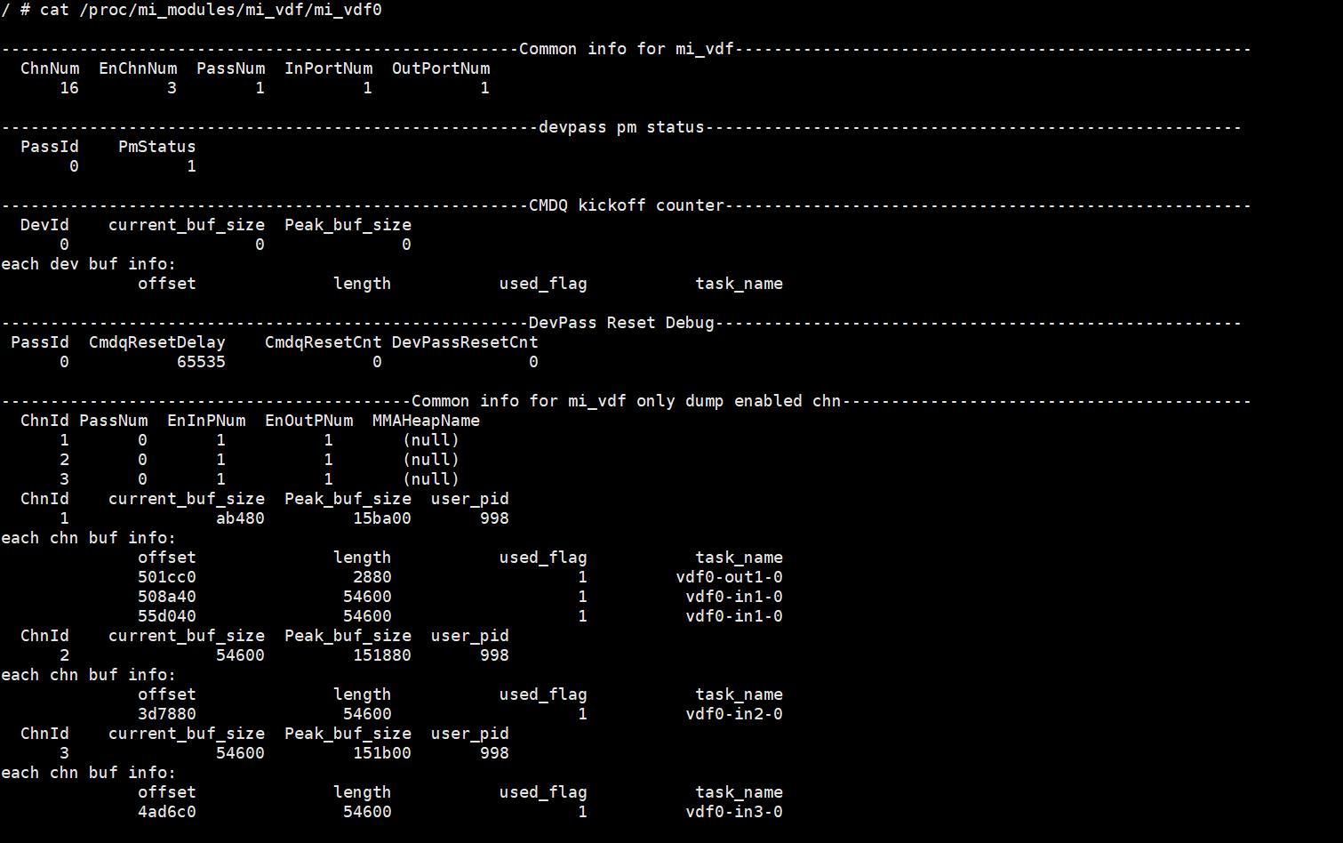
Table 1-1:
Parameter Description Common info for mi_vdf ChnNum The maximum channel number of the device EnChnNum The enabled channel number of the device PassNum The pass number of the device InPortNum The inport number of the device OutPortNum The outport number of the device CollectSize The number of allocators contained in the AllocatorCollection corresponding to the device Common info for mi_vdf only dump enabled chn ChnId Channel id PassNum Pass number EnInPNum The enabled input port number of the channel EnOutPNum The enabled output port number of the channel MMAHeapName If there is SetChnMMAConf, the value is the corresponding mma heap name; if it is not set, the value is NULL current_buf_size The size of the currently requested memory Peak_buf_size Peak memory usage user_pid Current process pid 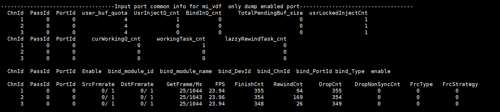
Table 1-2:
Parameter Description Input port bind info (only dump enabled Input port) ChnId The channel id of the input port PassId The pass id of the device PortId The InputPort id of the device user_buf_quota The quota buff number of the InputPort UsrInjectQ_cnt The buff number in UsrInjectBufQueue of the InputPort BindInQ_cnt The buff number in BindInputBufQueue of the InputPort TotalPendingBuf_size The buff total size in cur_working_input_queue of the InputPort usrLockedInjectCnt The buff count currently taken by the user layer newPulseQ_cnt The buff number in new_pulse_fifo_inputqueue of the InputPort nextTodoPulseQ_cnt The buff number in next_todo_pulse_inputqueue of the InputPort curWorkingQ_cnt The buff number in cur_working_input_queue of the InputPort workingTask_cnt The buff number in input_working_tasklist of the InputPort lazzyRewindTask_cnt The buff number in lazzy_rewind_inputtask_list of the InputPort (The task count that need to be retryed) Enable 1: Enable 0: Disable bind_module_id The module id of the output port binded with this input port bind_module_name The module name of the output port binded with this input port (For example, the mod name here is divp, divp→vdf) bind_ChnId The channel id of the output port binded with this input port bind_PortId The id of the output port binded with this input port bind_Type 0x00000001: Frame (Frame mode, default work mode)
0x00000002: sw_low_latency (Low-latency work mode)
0x00000004: realtime mode (Hardware direct connection work mode)
0x00000008: hw autosync (Before and after handshake, the buffer size is consistent with the image resolution)
0x00000010: hw ring (Before and after handshake, ring buffer depth can be adjusted)bind_Param Binded parameter enable Enable SrcFrmrate Source frame rate DstFrmrate Target frame rate GetFrame/Ms Actual frame rate/Time used FPS Actual frame rate FinishCnt Finished count RewindCnt The task count that need to be retryed 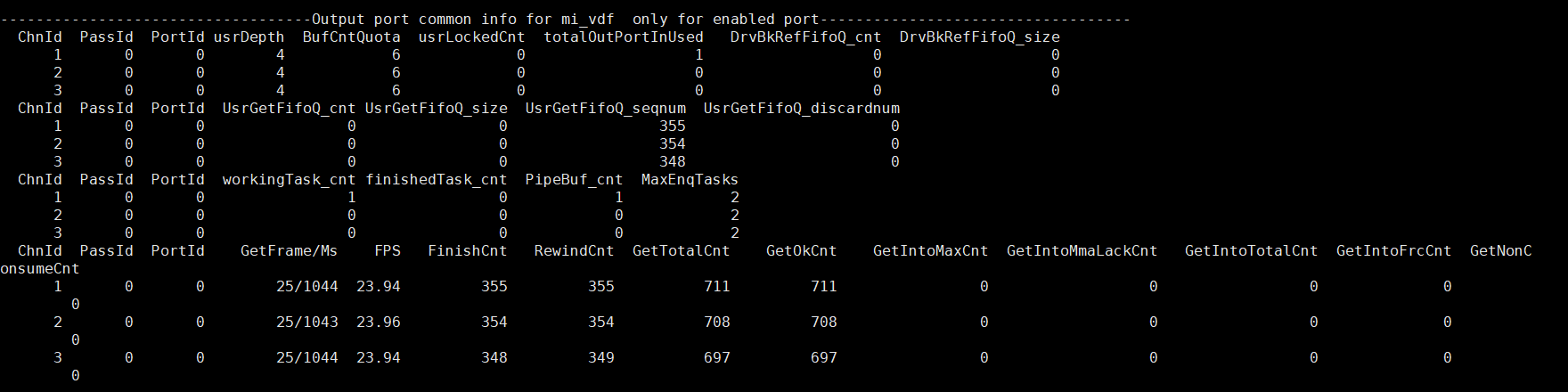
Table 1-3:
Parameter Description output port bind info(only dump enabled output port) ChnId The channel id of the output port PassId The pass id of the device PortId The output port of the device usrDepth The maximum number of output port buf that the user can get BufCntQuota The quota buff count of the OutputPort usrLockedCnt The buffer count actually taken by the user layer from UsrGetFifoBufQueue totalOutPortInUsed The buffer count actually applied for by Output DrvBkRefFifoQ_cnt The buffer number in DrvBkRefFifoQueue of the OutputPort (For special driver which need to refer back pre-processed buffer) DrvBkRefFifoQ_size The buffer size occupied in the DrvBkRefFifoQueue of the OutputPort UsrGetFifoQ_cnt The buffer count dumped in the UsrGetFifoBufQueue of the OutputPort UsrGetFifoQ_size The buffer size dumped in the UsrGetFifoBufQueue of the OutputPort UsrGetFifoQ_seqnum The buffer count got by the OutputPort UsrGetFifoQ_discardnum The cumulative number of discarded original buffers that the OutputPort discarded due to new buffer requirements. finishedTask_cnt The task count finished by the OutputPort GetFrame/Ms Actual frame rate/time used FPS Actual frame rate FinishCnt Finished count RewindCnt The task count that need to be retryed GetTotalCnt The buffer count got by the OutputPort GetOkCnt The frame count of E_MI_FRC_OBTAIN 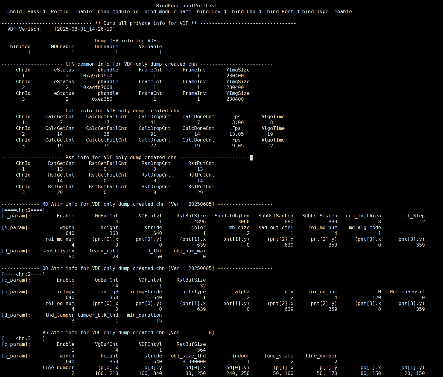
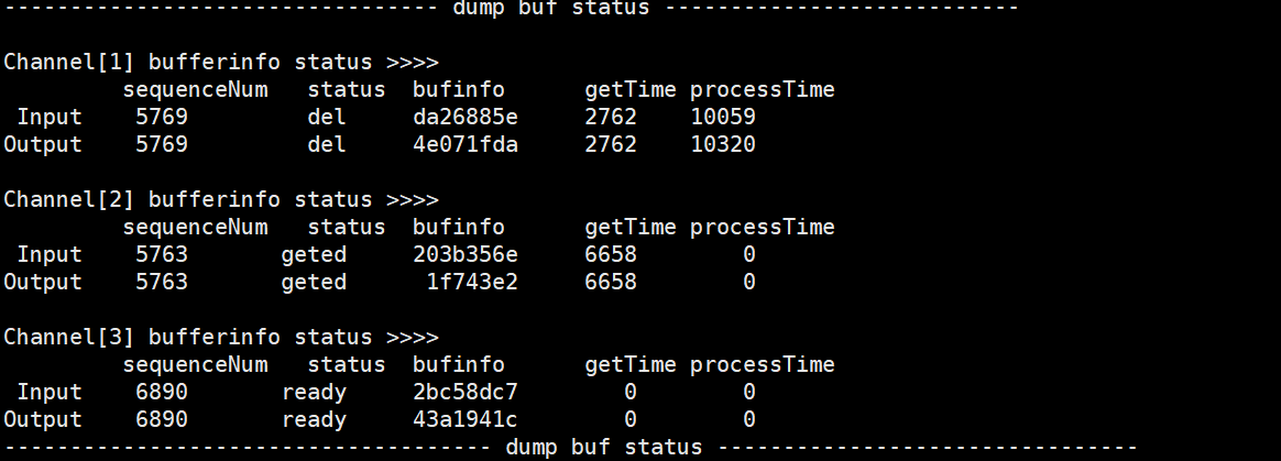
Table 1-4:
Parameter Description DEV info for VDF VDF Verison Version information bInited The Vdf module is initialized or not. (0-Disable, 1-Enable) MDEnable Enable MD or not. (0-Disable, 1-Enable) ODEnable Enable OD or not. (0-Disable, 1-Enable) VGEnable Enable VG or not. (0-Disable, 1-Enable) CHN common info for VDF (only dump created chn) ChnId Channel id eStatus 0: Destroy 1: created 2: start 3: stop phandle OD/MD/VG init handle pointer FrameCnt Frame count (Not used currently) FrameInv Interval frame (Not used currently) YImgSize A yImage size(height*width) size sent from the previous stage Calc info for VDF (only dump created chn) ChnId Channel Id CalcGetCnt The number of input image obtained successfully by vdf CalcGetFailCnt The number of input image obtained unsuccessfully by vdf CalcDropCnt The number of input image discarded by vdf CalcDoneCnt The number of input image processed successfully by vdf Fps The frame rate of the input image /td> AlgoTime The time consumed by the MD/OD/VG algorithm to process a frame(ms) Rst info for VDF (only dump created chn ) ChnId Channel Id RstGetCnt The number of times the user succeeded in obtaining the algorithm result RstGetFailCnt The number of times the user failed to obtain the algorithm result RstDropCnt The number of times the algorithm result was discarded (discarded by new data) RstPutCnt The number of times the user released the memory used by the algorithm result MD Attr info for VDF (only dump created chn) ChnId Channel id [c_param] Common parameter Enable Enable current channel or not MdBufCnt The Buffer count that MD stores the result VDFIntvl Not used currently RstBufSize The size of the result returned at one time SubRstObjLen The size of the CCL output result SubRstSadLen The size of the SAD output result SubRstStsLen The size of the checked result ccl_InitArea Threshold value of CCL area area ccl_Step The increase value of the threshold value for each increase in CCL [s_param] Static parameter width The Image width input by MD height The Image height input by MD stride The Image stride input by MD color The Image color input by MD mb_size MD macroblock size. 0: MB_4x4, 1: MB_8x8, 2: MB_16x16 sad_out_ctrl MD SAD output format. 0: 16BIT_SAD, 1: 8BIT_SAD md_alg_mode Algorithm mode of CCL Unicom area. 0: FG mode, 1: SAD mode roi_md_num Number of boundary points of detection area Pnt[i].x The x coordinate of each boundary point of the detection area Pnt[i].y The y coordinate of each boundary point of the detection area [d_param] Dynamic parameter sensitivity Algorithm sensitivity, range [10,20,30,…..100], the larger the value, the more sensitive learn_rate Unit milliseconds, range [1000,30000], used to control how long the front object stops moving before it is used as the background picture md_thr The threshold value for judging the movement, there are different setting standards for different modes obj_num_max CCL limit value for the number of connected regions OD Attr info for VDF (only dump created chn) ChnId Channel id [c_param] Common parameter Enable Enable current channel or not OdBufCnt The Buffer count that OD stores the result VDFIntvl Not used currently RstBufSize The size of the result returned at one time [s_param] Static parameter inImgW The Image width input by OD inImgH The Image height input by OD inImgStride The Image stride input by OD nClrType OD input image type 2-y data alpha Control the learning rate for generating reference images div Type of OD detection window
0: 1 window
1: 4 windows
2: 9 windowsM How many images update the reference image once MotionSensit Motion sensitivity setting roi_od_num Number of boundary points of detection area pnt[i].x The x coordinate of each boundary point of the detection area pnt[i].y The y coordinate of each boundary point of the detection area [d_param] Dynamic parameter thd_tamper Image difference ratio threshold tamper_blk_thd Threshold value of the number of occluded areas of the image min_duration Image difference duration threshold VG Attr info for VDF (only dump created chn) ChnId Channel id [c_param] Common parameter Enable Enable current channel or not VgBufCnt The Buffer count that VG stores the result VDFIntvl Not used currently RstBufSize The size of the result returned at one time [s_param] Static parameter width The Image width input by VG height The Image height input by VG stride The Image stride input by VG obj_size_thd The percentage size of the object in the area of interest indoor Camera mounting area 0-outdoor 1-indoor func_state Detection mode
2: VG_VIRTUAL_GATE, indicating that the mode is a virtual line segment.
3: VG_REGION_INVASION, indicating that the mode area is invaded.line_number The number of virtual line segments, support 1 to 4 virtual line segments (The detection mode is effective for VG_VIRTUAL_GATE) p[i].x X coordinate of line segment n (The detection mode is effective for VG_VIRTUAL_GATE) p[i].y Y coordinate of line segment n (The detection mode is effective for VG_VIRTUAL_GATE) pd[i].x The first direction point of line segment n (The detection mode is effective for VG_VIRTUAL_GATE) pd[i].y The second direction point of line segment n (The detection mode is effective for VG_VIRTUAL_GATE) region_dir Set the direction of the region invasion. There are currently three directions to choose from: entering, leaving, and crossing.
0-REGION_ENTER: Entering the alarm region triggers an alarm.
1-REGION_LEAVING: Leaving the alarm region triggers an alarm.
2-REGION_CROSS: Crossing the alarm region triggers an alarm. (The detection mode is effective for VG_REGION_INVASION)Pnt[i].x The x coordinate of the i-th point of the region. (The detection mode is effective for VG_REGION_INVASION) Pnt[i].x The y coordinate of the i-th point of the region. (The detection mode is effective for VG_REGION_INVASION) dump buf status Channel[xxx] channel id Input/Output sequenceNum The unique identifier of the buffer, the serial number id status The status of the buffer. (ready: vdf successfully applied for buf; geted: the algorithm successfully obtained buf; drop: abnormal situation, discard processing; done: algorithm operation is successful; del: memory to be released) bufinfo memory address of buffer getTime The time it takes for vdf to successfully obtain “task buffer” (us) processTime The time it takes for vdf to go from enqueueTask to dequeueTask(us)
5.2. echo
# echo help > /proc/mi_modules/mi_vdf/mi_vdf0
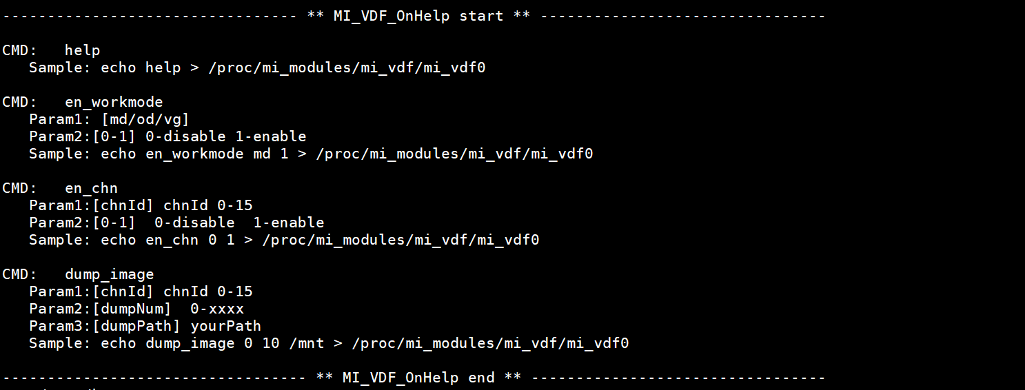
Echo help view available commands.
Table 2-1:
| Function | Enable/Disable en_workmode(od/md/vg) |
|---|---|
| Command | echo en_workmode param1 param2 > /proc/mi_modules/mi_vdf/mi_vdf0 |
| Parameter Description | param1: [md/od/vg] param2: [0-1] 0-disable, 1-enable |
| Example | echo en_workmode md 0 > /proc/mi_modules/mi_vdf/mi_vdf0 |
Table 2-2:
| Function | Enable/Disable vdf chn |
|---|---|
| Command | echo en_chn param1 param2 > /proc/mi_modules/mi_vdf/mi_vdf0 |
| Parameter Description | param1: [chnId] chnId 0-63 param2: [0-1] 0-disable, 1-enable |
| Example | echo en_chn 0 0 > /proc/mi_modules/mi_vdf/mi_vdf0 //cat /proc/mi_modules/mi_vdf/mi_vdf0 again, you can see that ch0 of input/output has been closed |
Table 2-3:
| Function | Dump yuv |
|---|---|
| Command | echo dump_image [param1, param2, param3] > /proc/mi_modules/mi_vdf/mi_vdf0 |
| Parameter Description | param1: [chnId] chnId 0-15 Param2: [dumpNum] 0-xxxx Param3: [dumpPath] yourPath |
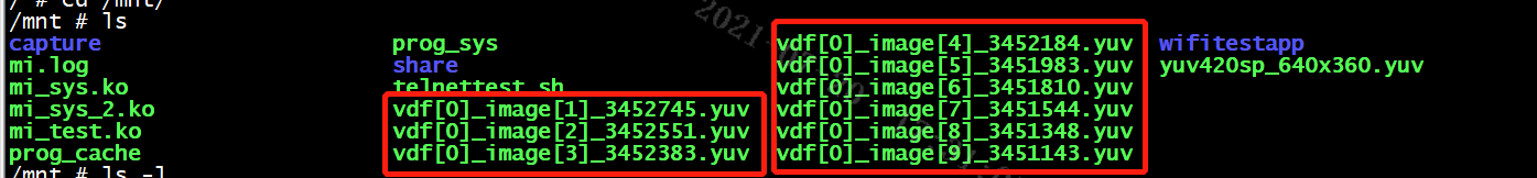
| Example | echo dump_image 0 10 /mnt > /proc/mi_modules/mi_vdf/mi_vdf0 |
For example, dump chn0 10 YUV in /mnt directory: