MI IPU Usage Guide
1. Feature Introduction
This demo mainly demonstrates how to insert IPU model inference into the sensor-to-RTSP pipeline. It uses MI IPU SDK to load the YOLOv8n model in this pipeline and displays detection results in real-time.
  +---------+      +---------+      +---------+                     +--------+     +--------+
  |   VIF   | ---> |   ISP   | ---> |   SCL   | ---port0:Source---> |  VENC  | --> |  RTSP  |
  +---------+      +---------+      +----+----+                     +--------+     +--------+
                                         |                               ^
                                         |                               |
                                         |                               |
                                         |                               |
                                         |         +--------+       +----+---+
                                  port1:Scaled---> |  IPU   | ----> |  RGN   |
                                                   +--------+       +--------+
- The IPU functionality is integrated into the pipeline. SCL port0 and port1 send bufferinfo from VIF at original resolution and bufferinfo scaled by SCL to the resolution supported by the IPU network model to IPU for processing. After obtaining the target coordinate information, the frame functionality of RGN is used to attach to VENC to draw detection boxes, encode together with the sensor data from port0 into an H264 stream, and finally send it out via RTSP protocol, allowing preview of the entire video stream and inference results on the PC.
- The default configured YOLOv8n model can recognize 80 types of objects and mark them with green boxes. The boxes display the recognized object category names in red font.
- When the character "q" is entered, the process exits.
2. Compilation Environment Description
Note
Generally, the corresponding programs are already packaged on the board by default, so sample_code program compilation is not mandatory. You can directly find prog_vif_sensor_ipu_demo in the /customer/sample_code/bin folder on the board. If you cannot find the file or need to modify the program, please refer to the following steps.
-
If you cannot find
prog_vif_sensor_ipu_demo, you can check whetherAPP_REL_PREFIX:= binis included in\sdk\verify\sample_code\source\iford\dla\sensor_ipu_demo\sensor_ipu_demo.mk. If not, you can add it to sensor_ipu_demo.mk, so that it will be packaged into the image together when compiling the project; -
Select defconfig in the project path based on the board (nand/nor, DDR model, etc.) for full package compilation
For example, for Comake PI D2 model board, using emmc and ddr4 configuration, use the following defconfig. For other board models, please refer to the user manual for details.
ipc_iford.emmc.glibc-11.1.0-ext4fs.ssc029d.256.bga8_lpddr4x_d2_full_defconfigExecute the following commands in the project directory for compilation:
export PATH=/tools/toolchain/gcc-sigmastar-9.1.0-2019.11-x86_64_arm-eabi/bin:/tools/toolchain/gcc-11.1.0-20210608-sigmastar-glibc-x86_64_arm-linux-gnueabihf/bin:$PATHexport CROSS_COMPILE=arm-linux-gnueabihf-export ARCH=armmake ipc_iford.emmc.glibc-11.1.0-ext4fs.ssc029d.256.bga8_lpddr4x_d2_full_defconfigmake clean && make image -j8 -
If there is a need to modify the program, you can cd into the
sdk/verify/sample_codedirectory and executemake clean && make source/iford/dla/sensor_ipu_demofor compilation; -
Get the executable file at
sample_code/out/arm/app/prog_vif_sensor_ipu_demo; -
Place the executable file
prog_vif_sensor_ipu_demoon the board at/customer/sample_code/binpath and modify permissions to 777.
3. Runtime Environment Description
The runtime environment configuration here is completely consistent with the sensor program. For details, please refer to Sensor Program Description 3.1 Single Sensor Runtime Environment Description description.
4. Resource File Description
- File location:
sdk/verify/sample_code/source/iford/dla/sensor_ipu_demo/resource/yolov8n_800x480_I6DW_fixed.sim_sgsimg.img - Package location: Automatically packaged to the board
/customer/sample_code/bin/resourcedirectory after full package compilation - Usage: Specify the model path through the
modelparameter when running the program
If you find that the model is not automatically packaged on the board, you can also copy it manually.
5. Running Instructions
cd to the board's /customer/sample_code/bin path and run prog_vif_sensor_ipu_demo
Parameter explanation:
prog_vif_sensor_ipu_demo index sensorIndex iqbin iqBinPath model modelPath 3dnr 3dnr_value calidata calidata_path
-
index + sensorIndex
The parameter input is to select
sensorIndex, the range is0-13. For the resolution list, refer to the table under the execution example. index0/index5 are picture formats, VENC does not currently support these two resource streams, index11/index12 are PWM dual sensor options which require modifying dts to enable switches. This demo does not support dual sensor recognitionindex 0, Crop(0,0,4032,3024), outputsize(4032,3024), maxfps 15, minfps 3, ResDesc 4032x3024@15fps index 1, Crop(0,0,3840,2160), outputsize(3840,2160), maxfps 21, minfps 3, ResDesc 3840x2160@21fps index 2, Crop(0,0,2016,1512), outputsize(2016,1512), maxfps 30, minfps 3, ResDesc 2016x1512@30fps index 3, Crop(0,0,1920,1080), outputsize(1920,1080), maxfps 30, minfps 3, ResDesc 1920x1080@30fps index 4, Crop(0,0,3264,2448), outputsize(3264,2448), maxfps 30, minfps 3, ResDesc 3264x2448@30fps index 5, Crop(0,0,4032,3024), outputsize(4032,3024), maxfps 30, minfps 3, ResDesc 4032x3024@30fps index 6, Crop(0,0,3840,2160), outputsize(3840,2160), maxfps 30, minfps 3, ResDesc 3840x2160@30fps index 7, Crop(0,0,1920,1080), outputsize(1920,1080), maxfps 60, minfps 3, ResDesc 1920x1080@60fps index 8, Crop(0,0,1008,756), outputsize(1008,756), maxfps 200, minfps 3, ResDesc 1008x756@200fps index 9, Crop(0,0,2560,1440), outputsize(2560,1440), maxfps 30, minfps 3, ResDesc 2560x1440@30fps index 10, Crop(0,0,1920,1080), outputsize(1920,1080), maxfps 60, minfps 3, ResDesc 1920x1080@60fps_master_xvs index 11, Crop(0,0,1920,1080), outputsize(1920,1080), maxfps 60, minfps 3, ResDesc 1920x1080@60fps_slave_pwm_low index 12, Crop(0,0,1920,1080), outputsize(1920,1080), maxfps 60, minfps 3, ResDesc 1920x1080@60fps_slave_pwm_high choice which resolution use, cnt 13 -
iqbin + iqBinPath
Path to load iqbin
Note
Please refer to the table below for correspondence with resolutions when selecting IQ BIN.
| Resolution | IQ File | Note |
|---|---|---|
| 4032x3024@15fps | NA | Not supported |
| 3840x2160@21fps | imx681_8m_comake_1201_30fps.bin | NA |
| 2016x1512@30fps | imx681_3m_comake_1201_30fps.bin | NA |
| 1920x1080@30fps | imx681_3m_comake_1201_30fps.bin | NA |
| 3264x2448@30fps | imx681_8m_comake_1201_30fps.bin | NA |
| 4032x3024@30fps | NA | Not supported |
| 3840x2160@30fps | imx681_8m_comake_1201_30fps.bin | NA |
| 1920x1080@60fps | imx681_2m_comake_1201_60fps.bin | NA |
-
model + modelPath
The parameter
modelinput is the file path of the model. -
3dnr + 3dnr_value
Whether to enable 3dnr, 0: off, 1: on.
-
calidata + calidata_path
Path to load calidata
Execution Examples
-
Configure USB as RNDIS network card, cd to
/customer/sample_code/bin/resource, run./setup_rndis.sh. By default, it will bring up the usb0 network card. Enterifconfigand the following log will appear:usb0 Link encap:Ethernet HWaddr E6:46:AC:2F:77:56 inet addr:192.168.7.2 Bcast:192.168.7.255 Mask:255.255.255.0 UP BROADCAST RUNNING MULTICAST MTU:1500 Metric:1 RX packets:48 errors:0 dropped:31 overruns:0 frame:0 TX packets:0 errors:0 dropped:0 overruns:0 carrier:0 collisions:0 txqueuelen:1000 RX bytes:3400 (3.3 KiB) TX bytes:0 (0.0 B)At this time, a virtual RNDIS network card will be enumerated on the PC. You can check it through "Right-click -> Start -> Device Manager -> Network Adapters". Usually the name is
USB Ethernet/RNDIS Gadget. If this device does not exist, the computer may not have the RNDIS driver installed. You can refer to link Chapter 4 for installation:https://dev.comake.online/home/article/7672 -
Run single sensor IPU model inference example:
./prog_vif_sensor_ipu_demo index 3 model ./resource/yolov8n_800x480_I6DW_fixed.sim_sgsimg.img iqbin /config/iqfile/imx681_3m_comake_1201_30fps.bin 3dnr 1 calidata /config/iqfile/3m_ne_cali.data
6. Running Results Description
-
View results
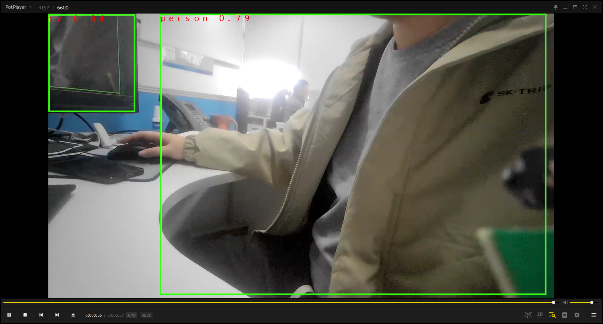
Select to run and enter the single sensor IPU model inference scenario. Run video playback software such as VLC Media Player or PotPlayer on the PC terminal, and play by opening the link
rtsp://192.168.7.2/6600. When playback is successful, you can see the sensor image. Recognized objects in the image will be marked with boxes. Multiple detected objects can be boxed simultaneously, and the detected object names will be marked in red font on the detection boxes.